3.3 Drawing Views
D.M. Donner
Assembly Drawing
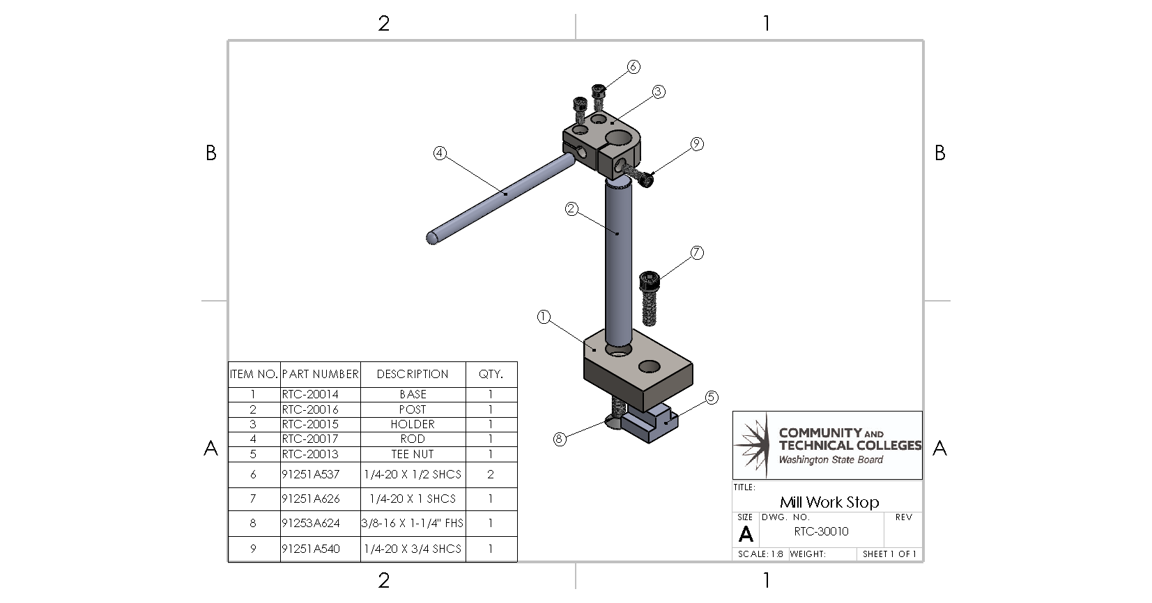
Assembly drawings show how all the parts of an assembly fit together and the functional relationship between them. The above figure of a mill work stop illustrates how all the parts of the object go together. Two views are used in the drawing space. On the right is the mill work stop assembled into the final configuration for use. The view on the left is an exploded view where all the pieces of the object are separated from the assembly but still maintain a relationship as to the order in which they fit in the assembly. From the exploded view drawing, the viewer can understand that item 9, a ⅜” socket head cap screw, mates with the counterbore in item 1, the base, and threads into item 5, a T-nut.
The assembly view has the added advantage of incorporating a Bill of Materials (BOM). A BOM is a comprehensive list of all the materials, parts, components, and sub-assemblies needed to manufacture or build a product as depicted in an engineering drawing. The assembly drawing in the figure above has a BOM in the bottom left corner of the print. It provides detailed information about the quantity, description, part numbers, and other relevant attributes for each item.
In the context of an engineering drawing, a BOM typically accompanies the drawing to ensure that all the necessary components and materials are accounted for in the manufacturing or assembly process. The BOM serves as a reference for procurement, production planning, cost, and inventory management.
Detail Drawings
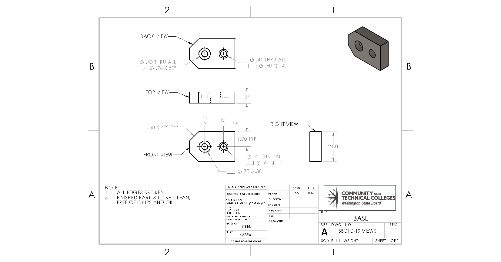
Detail drawings are graphical representations that provide specific and comprehensive information about an individual component, part, or section of a larger product, structure, or system. Detail drawings are the primary type used by machinists on the shop floor. The drawing must communicate all the desired features in a detailed manner, which allows the technician to measure each feature as it is made.
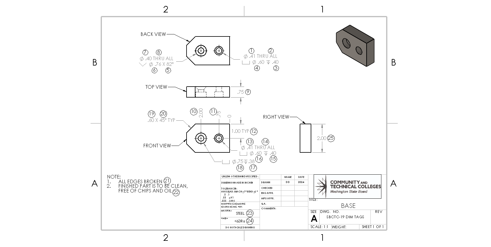
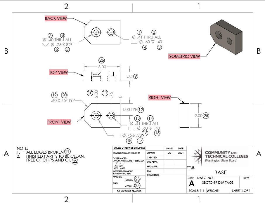
It is common practice for machine shops to modify detail drawings by adding dimension tags (DIM tags) which correlates a specific dimension to a simple numbering system that is used to complete FAIs and In-process checks. For example, the height of the part in the above figure is controlled by DIM tag 25.
| SBCTC-19 BASE FAI | ||
| DIM TAG | DIM | MEASURED DIMENSION |
|---|---|---|
| 1 | 0.41 | N/A |
| 2 | THRU | GOORNO-GO |
| 3 | 0.40 | N/A |
| 4 | 0.60 | N/A |
| 5 | 82° | GO/NO-GO |
| 6 | 0.76 | N/A |
| 7 | 0.40 | N/A |
| 8 | THRU | GO/NO-GO |
| 9 | 0.75 | N/A |
| 10 | 2.00 | N/A |
| 11 | 0.75 | N/A |
| 12 | 1.00 | N/A |
| 13 | 0.41 | N/A |
| 14 | THRU | GO/NO-GO |
| 15 | 0.40 | N/A |
| 16 | 0.60 | N/A |
| 17 | 0.38 | N/A |
| 18 | 0.75 | N/A |
| 19 | 0.60 | N/A |
| 20 | 45° | N/A |
| 21 | EDGE BREAK | GO/NO-GO |
| 22 | CLEAN | GO/NO-GO |
| 23 | STEEL | CERTS GO/NO-GO |
| 24 | <63Raμ” | N/A |
| 25 | 2.00 | N/A |
| 26 | 3.00 | N/A |
When a setup machinist is producing the first part of a new run, they must complete a First Article Inspection (FAI). An FAI is a production validation process that verifies that a new or modified production process produces conforming parts. It is an important step in the manufacturing process that ensures products are made to the correct specifications and meet customer requirements.
The FAI is an inspection document from which the inspection plan is created, and it lists all the dimensions found on a detailed drawing. The FAI has provisions for the setup machinist to record actual measurements taken from the first run part (setup part). The FAI is a critical document that the manufacturer uses to ensure they are indeed making the part as designed. This FAI process takes a considerable amount of time and effort, and production may not proceed until it is complete. Not all parts require an FAI. If the customer is from a sector that requires them, such as aviation, they must be completed; however, not all sectors demand them, such as food processing.
In-Process Checks (IPCs) are routine checks performed during production to ensure that the product quality is met. These checks can be performed during manufacturing or packing. IPCs are performed by production machinists throughout the manufacturing process to ensure DIMs stay within tolerance. A manufacturing planner decides which DIMs from the FAI need to be verified throughout production, and the production machinist performs these inspections and documents the results.
Notes on a detail drawing are common, and they communicate information that is outside the built-in features of a detail sheet. In the example above, the edge break is called out (DIM tag 21) in a note, as are the parts needing to be clean and free of oils (DIM tag 22). Both of these notes are important, especially since most parts proceed to some sort of outside processing before ultimately returning to the customer.
PART VIEWS
The primary views are the fundamental pictorial views utilized to illustrate the most information about the part. This procedure is referred to as orthographic projection. Orthographic projections are used to represent a three-dimensional object in a two-dimensional drawing. These views provide a comprehensive and accurate representation of the object from different directions, enabling a complete understanding of its shape, size, and features.
The most common primary views are the front, top, and right side views. These three primary views are typically arranged orthogonally to each other, forming the foundation of orthographic projection. The combination of front, top, and right side views gives a comprehensive understanding of the object’s geometry in three dimensions. When necessary, more views may be added to convey a better understanding of the object.
An orthographic view is created by projecting a viewing side of the part onto a plane parallel to that surface. That surface is then turned to be parallel to the front plane of the part.
Orthographic Projected View
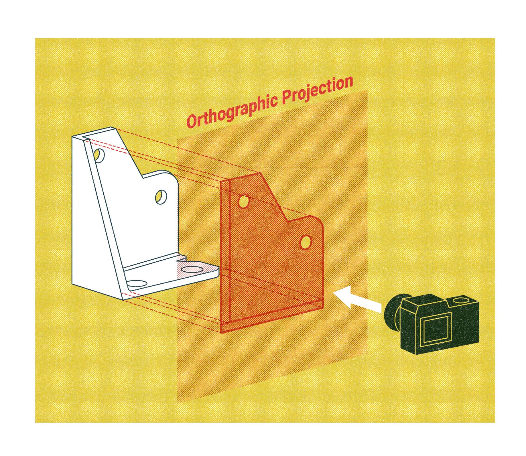
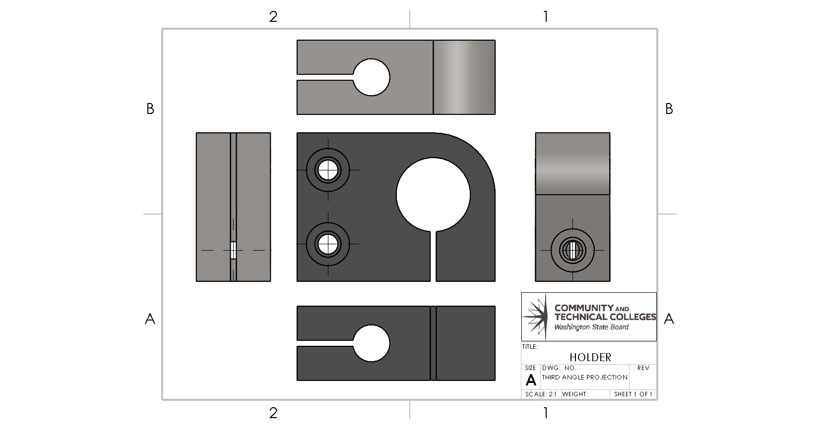
In the figure above, the part’s defining edges are projected onto a plane parallel to the face of the part, and between the part and the viewer. This is called third angle projection.
If the image was projected onto a plane behind the part in relation to the viewer, this would be first angle projection. In both first and third-angle projections, solid lines represent edges which are visible from that view. Dashed lines are lines that are not visible but are represented for clarity.
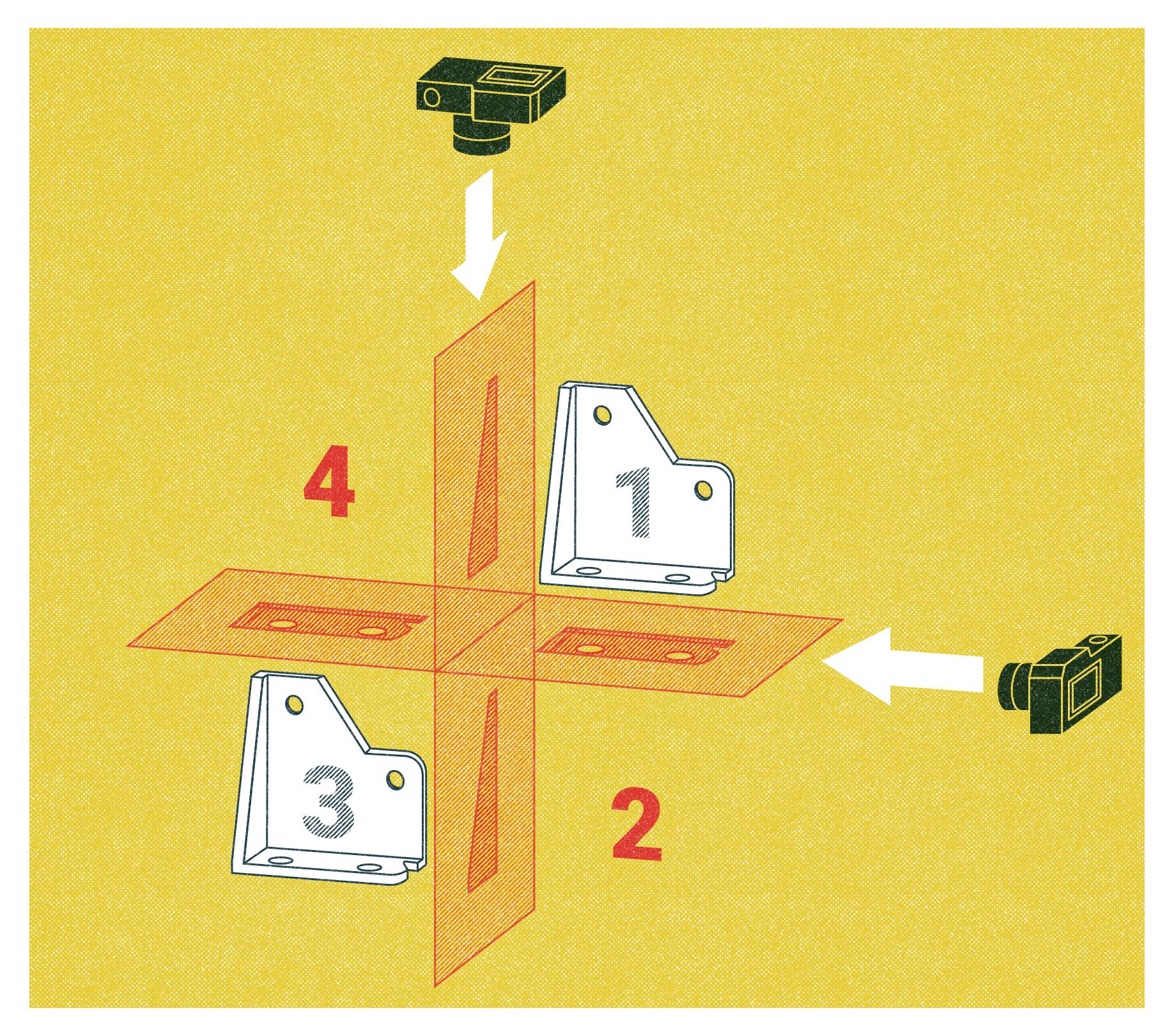
The terms first and third angle projection refer to a part’s location within a four-quadrant assimilation of planes in which the viewing direction is from the right and the top of the quadrants.
When an object is placed in quadrant three, lines are projected onto the planes between the object and the viewer. This is what is predominately used in North America.
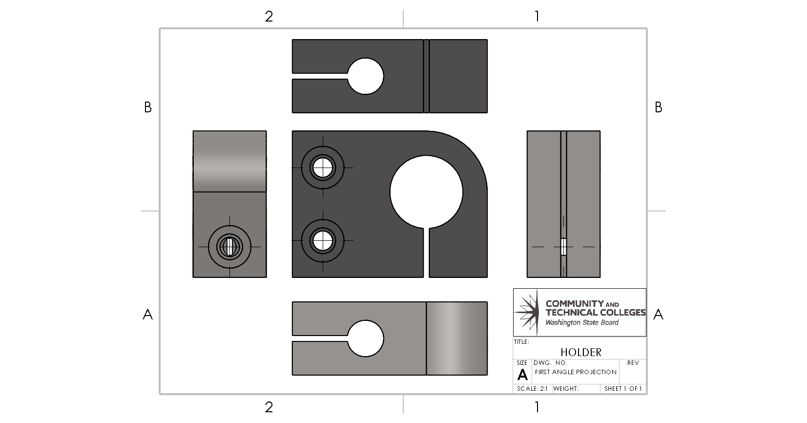
If an object is placed in the first quadrant and lines are projected onto the adjacent planes, the projection would be from the back of the part in relation to the viewer. The first angle projection is primarily used in European countries.
Front view
One view is chosen to be the front view. This view usually communicates the most information about an object. Two more views are selected to better define the object in three dimensions. The TOP and RIGHT views are given primary consideration; however, the engineer may choose which views provide the most information
Detail View
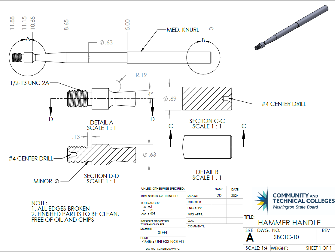
A detail view on a drawing provides a close-up of a selected section of a larger view. It can be especially useful when a large part has many important dimensions in a small area. Detail views can improve the readability of these measurements. Detail views have a circle outlining the area to be examined (see detail A: enclosing the threaded end of the handle threads above). The letter attached to the detail view orients the viewer to the image’s information. The detail view is enlarged and provides additional space for dimensioning. The figure above has two detailed views (A & B), allowing the engineer to accurately dimension both ends of the hammer handle.
Attributions
- Figure 3.5: Assembly drawing of a mill work stop by Damon Donner, for WA Open ProfTech, © SBCTC, CC BY 4.0
- Figure 3.6: Detail drawing of an object by Damon Donner, for WA Open ProfTech, © SBCTC, CC BY 4.0
- Figure 3.7: Detail drawing with DIM tags by Damon Donner, for WA Open ProfTech, © SBCTC, CC BY 4.0
- Figure 3.8: Labeled views on a detail drawing by Damon Donner, for WA Open ProfTech, © SBCTC, CC BY 4.0
- Figure 3.9: Third angle projection orthographic projected view, Front by Nicholas Malara, for WA Open ProfTech, © SBCTC, CC BY 4.0
- Figure 3.10: First and third angle projection views by Nicholas Malara, for WA Open ProfTech, © SBCTC, CC BY 4.0
- Figure 3.11: Third angle projection by Damon Donner, for WA Open ProfTech, © SBCTC, CC BY 4.0
- Figure 3.12: First angle projection by Damon Donner, for WA Open ProfTech, © SBCTC, CC BY 4.0
- Figure 3.13: Detail views of both ends of a hammer handle by Damon Donner, for WA Open ProfTech, © SBCTC, CC BY 4.0
a comprehensive list of all the materials, parts, components, and sub-assemblies needed to manufacture or build a product as depicted in an engineering drawing
graphical representations that provide specific and comprehensive information about an individual component, part, or section of a larger product, structure, or system.
Correlates a specific dimension to a simple numbering system that is used to complete FAIs and In Process Checks
A FAI is a production validation process that verifies that a new or modified production process produces conforming parts
are routine checks performed during production to ensure that the product quality is met.
A means of representing a three dimensional drawing in two dimensions for the purpose of feature identification
the 3D object is seen to be in the 3rd quadrant. It is positioned below and behind the viewing planes, the planes are transparent, and each view is pulled onto the plane closest to it. The front plane of projection is seen to be between the observer and the object.
Also known as European Projection, the object is placed in the first quadrant, top-right, of a right-handed coordinate system, and the projection planes are stated between the observer and the object.
provides a close-up of a selected section of a larger view.
