3.4 Lines
D.M. Donner
Solid Lines
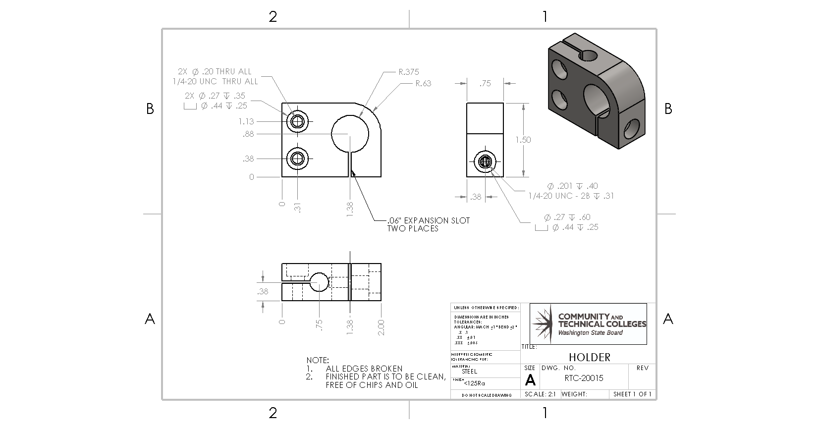
Solid lines projected in any view are considered to be the lines visible from that view. In other words, all visible edges are projected onto the viewing plane.
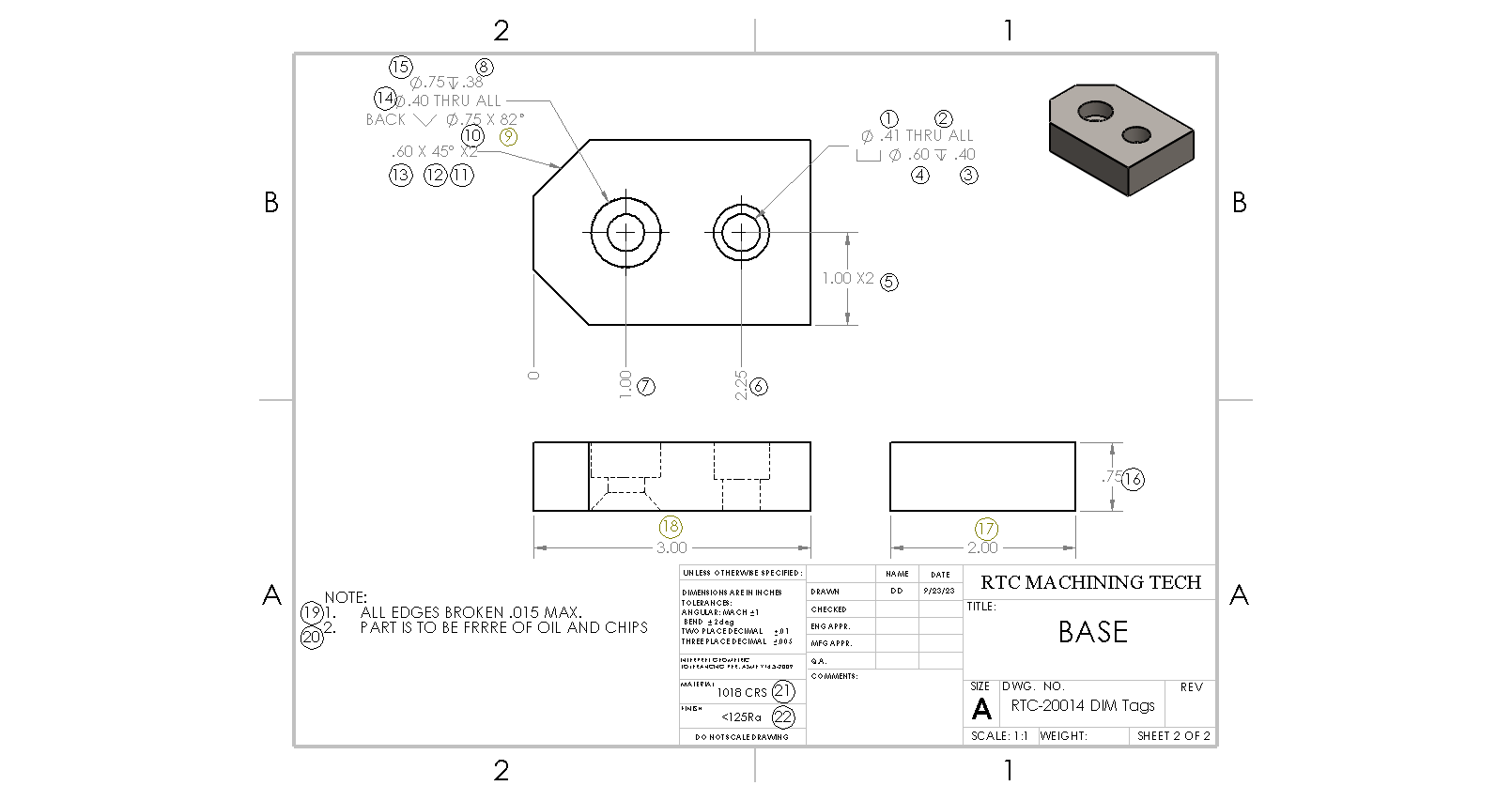
Hidden Lines
Hidden lines are feature lines that are not visible from the viewing plane and are represented by a broken or dashed line. They are either on the other side of the object or inside the object. Hidden lines are projected onto the view to provide useful information about a feature. In the above figure, the bottom left object uses hidden lines to help explain the hole features. The left-hand hole has a countersink on the top surface and a counterbore on the bottom surface. This is a non-standard use of these features, so using hidden lines will help the machinist understand this hole feature better.

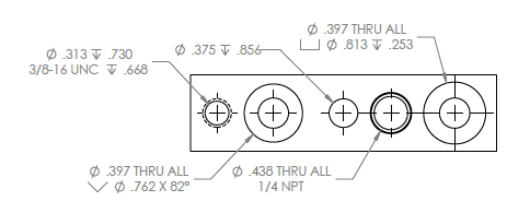
Leader Lines
A leader line in a drawing is a thin, continuous line that connects a feature in a drawing to text. In the above figure, a part has five different holes, all with specific information that details how a machinist must create the hole. The use of a leader line shows the relationship between the text and the feature.
Center Lines
Center lines are thin, long-short-long lines that indicate the centers of symmetrical objects, arcs, and holes. They can also represent symmetry and paths of motion.
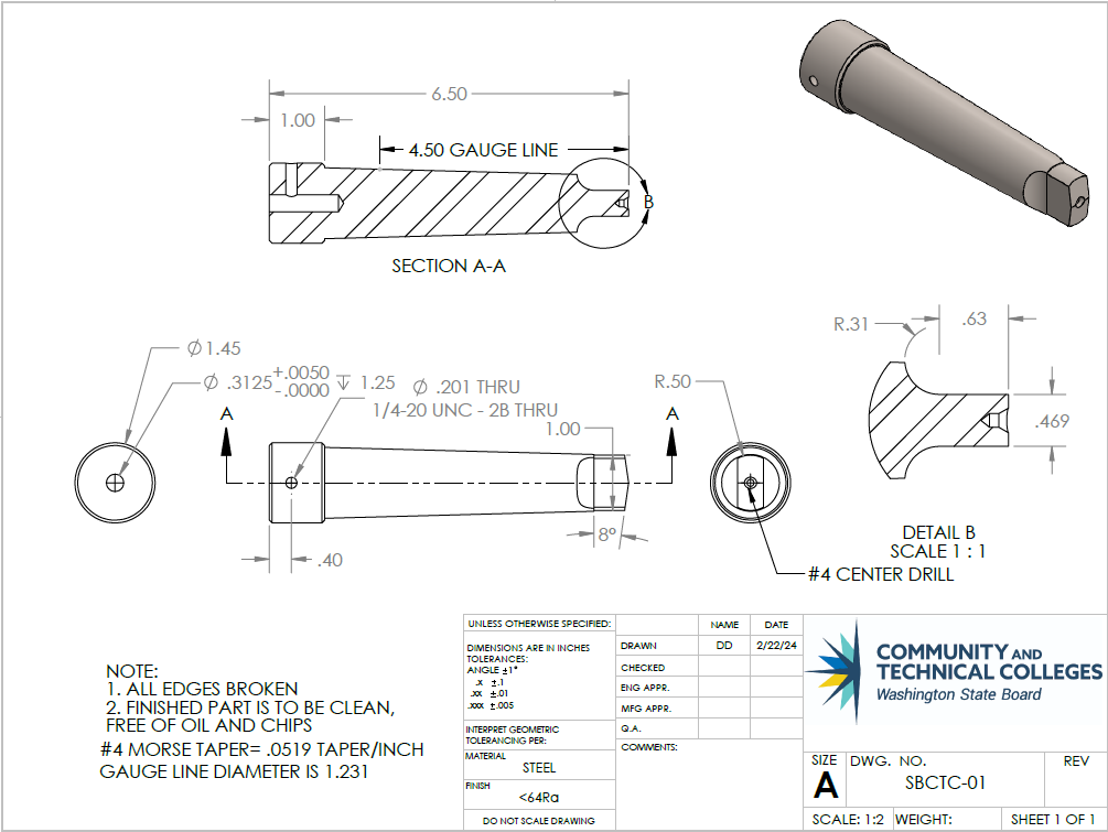
Cutting Plane Lines
Cutting plane lines are thick, dashed lines that run through the inside of an object to show where an imaginary cut has been made. Cutting plane lines allow the viewer to understand the orientation of a section view by creating the insertion of this plane. In the image above, the cutting plane lines are denoted as A-A.
Section View
When parts become complex and solid or hidden lines cannot express the detail necessary, section views are created using cutting planes. In the above figure, the cutting plane (A-A) is through the center of the part lengthwise and pointed up. The section view below the cutting plane represents what you will see at that instance.
Attributions
- Figure 3.14: Drawing lines by Damon Donner, for WA Open ProfTech, © SBCTC, CC BY 4.0
- Figure 3.15: Hidden lines illustrating the fastener details by Damon Donner, for WA Open ProfTech, © SBCTC, CC BY 4.0
- Figure 3.16: Leader lines connecting text to features by Damon Donner, for WA Open ProfTech, © SBCTC, CC BY 4.0
- Figure 3.17: Center lines in circular features. by Damon Donner, for WA Open ProfTech, © SBCTC, CC BY 4.0
- Figure 3.18: Cutting plane line by Damon Donner, for WA Open ProfTech, © SBCTC, CC BY 4.0
feature lines which are not visible from the viewing plane and are represented by a broken or dashed line.
continuous line that connects a feature in a drawing to text
thin, long-short-long lines that indicate the centers of symmetrical objects, arcs, and holes.
thick, dashed lines that run through the inside of an object to show where an imaginary cut has been made
a section view is a view perspective in relation to the cutting plane lines drawn through a part.
