4.2 Measuring Equipment and Decimals
D.M. Donner
What piece of measuring equipment should you use? The answer is based on a few details, such as:
- What type of dimension are you measuring? Length, depth, radius, diameter, inside dimension, outside dimension…
- What type of measuring instrument do you need? A gage or direct measurement instrument?
- Are there space limitations? Measuring an o-ring groove, for example.
- And finally, what is the resolution of the dimension? (.1, .01, .001, …)
Measuring equipment is designed to be used for specific purposes and, in some cases, has a singular purpose. One of these instances is when measuring threads to ensure they comply with an engineer drawing. For example, a ½-13 UNC 2B thread gage can only verify that specific class of fit thread. Many different gages are needed to verify different sizes and classes of fit. Threads and classifications will be discussed later.
On the other hand, the slide caliper can be used for four different measuring types and is good for three decimal places in an experienced hand. A slide caliper is a measuring tool used to measure inside, outside and depth dimensions. This tool uses a set of measuring surfaces attached to two different sliding mechanisms.
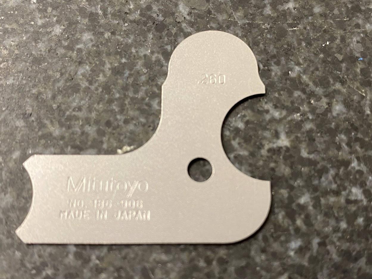
A gage is a specific type of measuring equipment that is primarily used to measure a single quantity or attribute. The figure above shows a radius gage. This radius gage is used to measure .260″ radius. A Go/No-Go gage is another type of gage used in quality control measuring. This type of gage measurement requires two pins: one that fits (go) a feature, and one that does not (no-go).
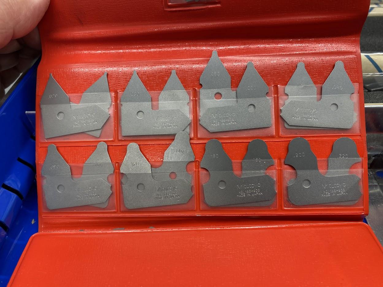
Due to their singular function, gages typically come in sets which can make this type of measuring equipment more expensive to purchase. As machinists, we are responsible for verifying that dimensions are within tolerance. The use of a properly set-up go/no-go gage, for instance, provides us with this information. We will discuss more about gages and how to use them later in this chapter.
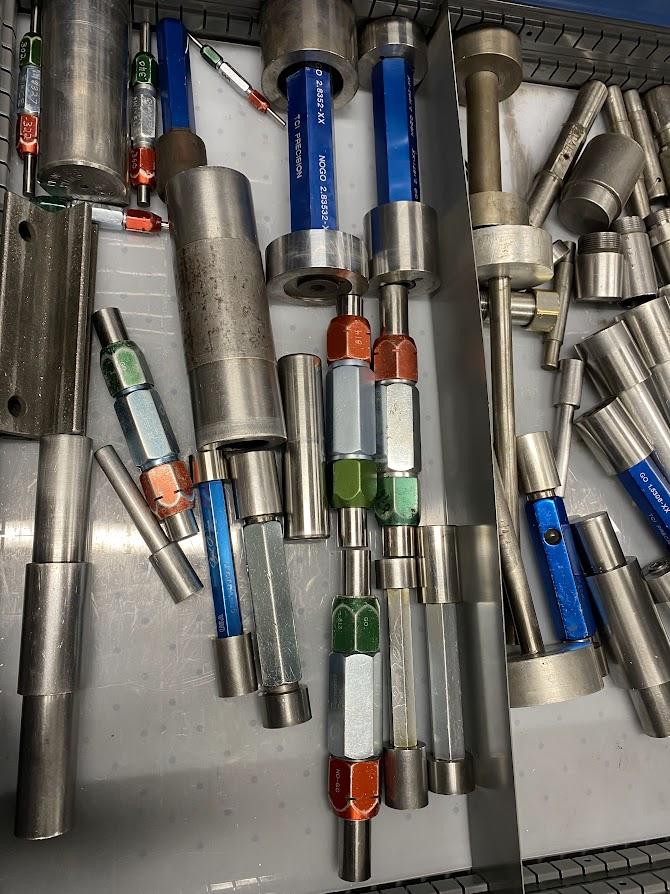
The figure above shows a drawer full of assembled go/no-go pin gages designed to gage holes. Many go/no-go gages are locally assembled for specific dimensions, where the operator will ensure the go gage fits the feature and the no-go gage will not. Notice this practice does not provide the specific dimension of a feature but only provides IN tolerance or OUT of tolerance feedback. If you need to verify a tap drill hole for a ½-13 UNC 2B thread, you can use a go/no-go pin gage. If the tap drill is 27/64ths (.4219), and let’s assume there is a three decimal tolerance of ∓.005″ (.427-.417), we can set up a .417 go and .428 no-go gage pin set to verify this hole feature.
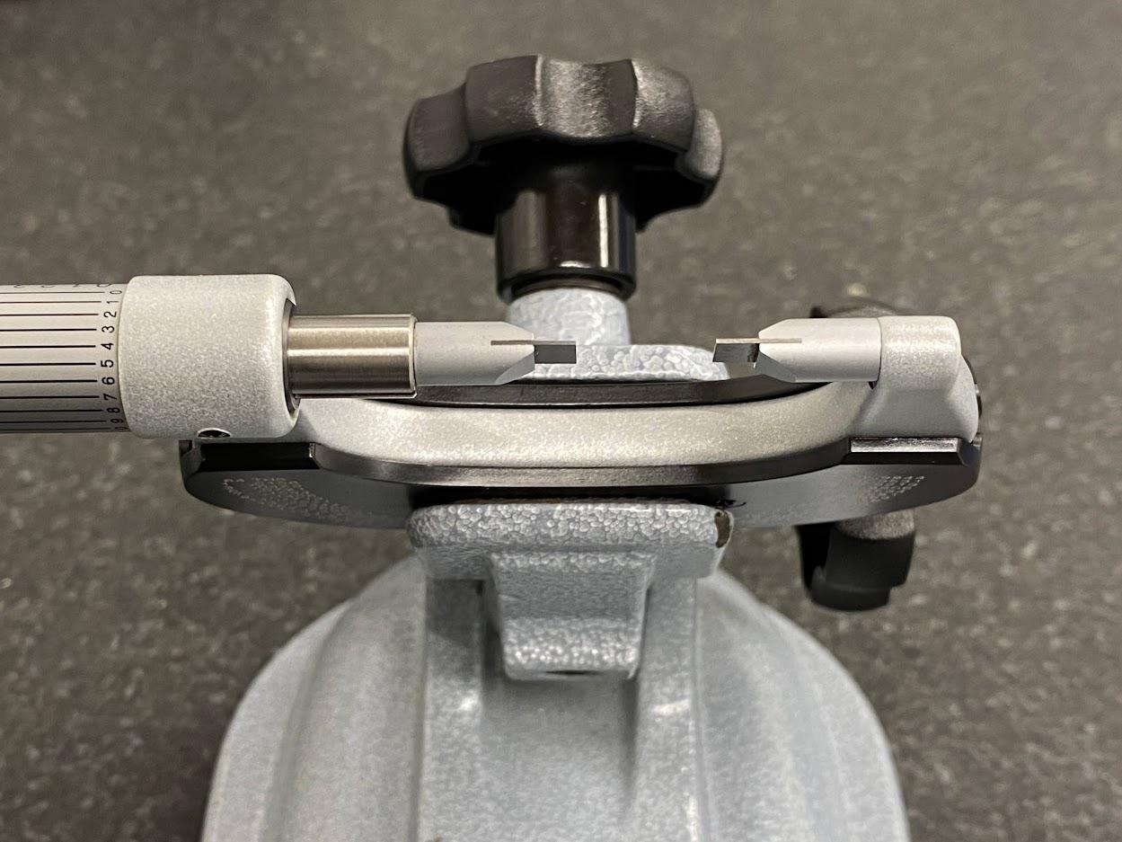
The above figure is an example of needing a specific piece of inspection equipment to measure a dimension. When measuring small grooves, a blade micrometer is the only tool that will fit, and it has a resolution of four decimal places.
Direct read measuring equipment provides numerical values or readings which represent a measured quantity.
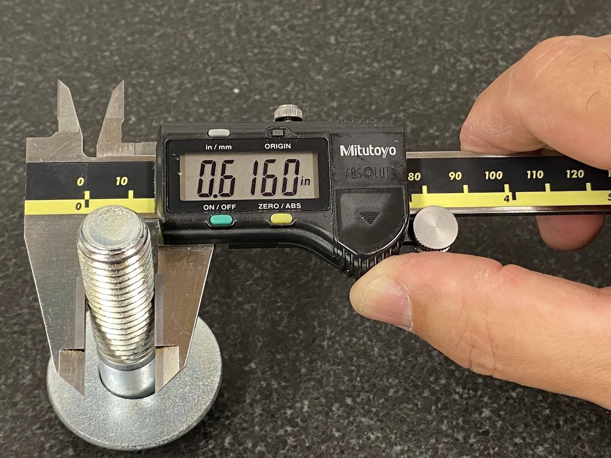
Direct read measuring equipment has the added value of measuring multiple dimensional values, which makes these tools more versatile than gages. In the example above, we know the diameter of the bolt is .616″.
In selecting the correct measuring equipment, the number of decimal places in the dimension to be measured is another factor.
Machinists follow the rule of 10X. The 10X rule requires measuring equipment to be ten times more accurate than the dimension being measured. Remember, ten times means one additional decimal place. If you must measure a two place decimal, then you may use a caliper because a caliper measures to the thousandths (0.001″) or three decimal places.
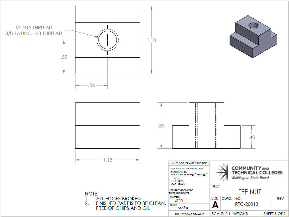
In the above figure, all the dimensions are two decimal places. This will require measuring equipment capable of accurately measuring to three decimals, such as a slide caliper.
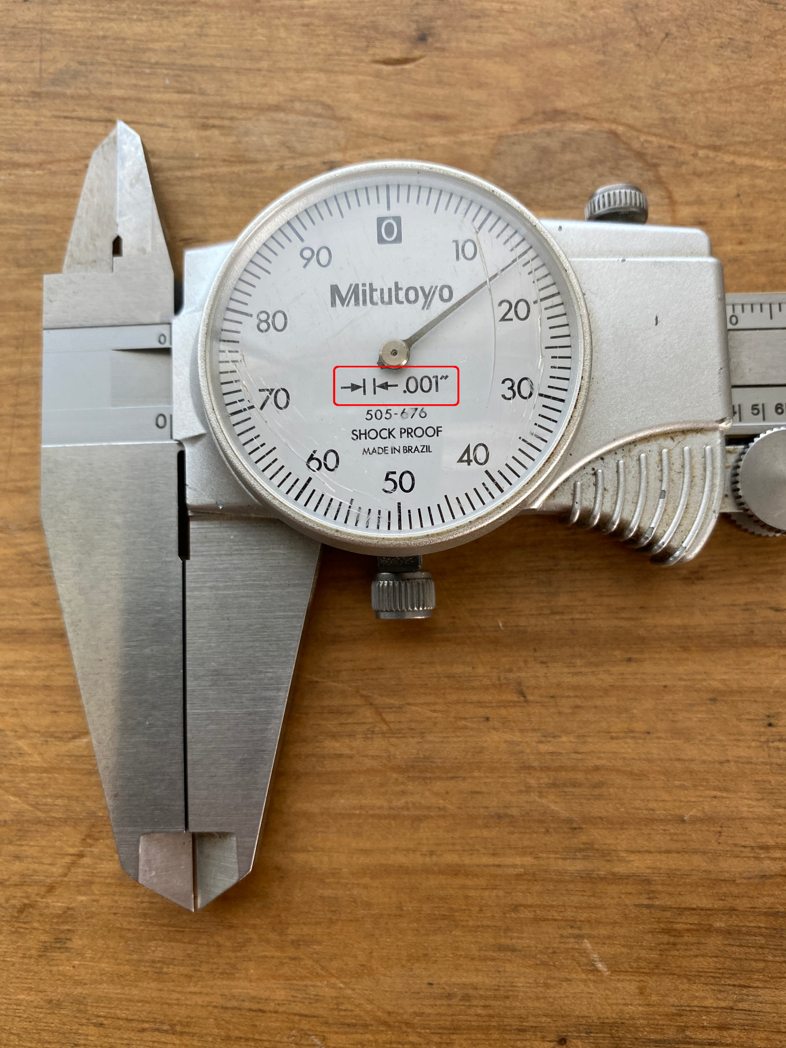
Figure 4.7. A dial caliper used to measure three decimal dimensions has a legend in the bezel explaining that every mark equals .001”. / Image Credit: Damon Donner, CC BY 4.0
The above dial caliper is capable of a .001″ resolution, as indicated by the information outlined in the red box.
The display has a legend, which explains the resolution of the caliper. The common legend used is two arrows pointing toward each other and touching two vertical lines (see red box). The vertical lines represent the resolution lines (tic lines) around the dial, where every line equals .001″. Because this dial shows that the finest resolution is .001″, it can be used for any dimension of two decimal places or less.

Author’s Tip
There are machinists in the industry who have been wielding calipers for a very long time, and they are capable of using them to measure in minute increments. For the purpose of an introductory level of understanding, stay with the ten times greater rule.
The digital calipers above have a display of four decimal places, or the tenths column. You would think that since there are four decimal places, you would be able to measure thousandths of decimals. Even the manufacturer’s literature states the indicator has ten thousandths resolution, but this is not true. The fourth decimal place digit in digital calipers is either a zero or a five. This means that with experience and a trained hand, the operator can use them to measure to a half thou.
For the purpose of this book and the skill level intended, the slide caliper is a three decimal piece of measuring equipment.
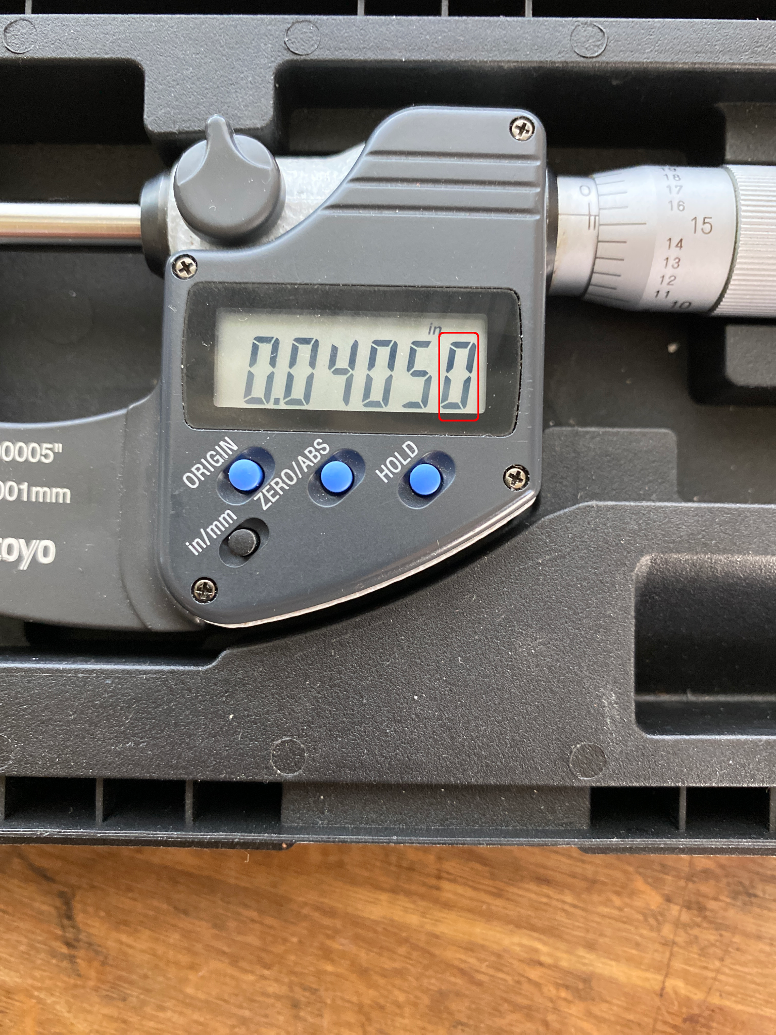
For a three decimal dimension, you would need a resolution of four decimal places or ten thousandths, or “tenths”. The digital micrometer in figure 4.9 has a display of four decimal places and a zero or a five (red box). The micrometer is designed to measure three decimal place dimensions because the display accurately shows four decimal places, or “tenths” and this abides by the rule of ten times more accuracy.
We now know what type of measuring equipment to use for various dimensions. The remainder of this chapter will discuss specific types of measuring equipment and how to use them.
Attributions
- Figure 4.1: Radius gage by Damon Donner, for WA Open ProfTech, © SBCTC, CC BY 4.0
- Figure 4.2: A set of radius gages by Damon Donner, for WA Open ProfTech, © SBCTC, CC BY 4.0
- Figure 4.3: Go/no-go pin gages by Damon Donner, for WA Open ProfTech, © SBCTC, CC BY 4.0
- Figure 4.4: Blade micrometer by Damon Donner, for WA Open ProfTech, © SBCTC, CC BY 4.0
- Figure 4.5: Example of direct measuring equipment by Damon Donner, for WA Open ProfTech, © SBCTC, CC BY 4.0
- Figure 4.6: Decimal place dimensions by Damon Donner, for WA Open ProfTech, © SBCTC, CC BY 4.0
- Figure 4.7: Dial caliper with a .001″ resolution by Damon Donner, for WA Open ProfTech, © SBCTC, CC BY 4.0
- Figure 4.8: Digital caliper resolution by Damon Donner, for WA Open ProfTech, © SBCTC, CC BY 4.0
- Figure 4.9: Micrometer digital display by Damon Donner, for WA Open ProfTech, © SBCTC, CC BY 4.0
a measuring tool used to measure inside, outside and depth dimensions utilizing a set of measuring surfaces attached to two different mechanisms which have a sliding relationship to one another.
is a specific type of measuring equipment that is primarily used to measure a single quantity or attribute
a manual measuring gage of two different sizes. One size is the largest size which should fit and another which is is just above the tolerance zone and will not fit a feature. They do not tell you the size of a feature, just that the feature is within tolerance
an inspection instrument that provides numerical values or readings of a feature when measured
requires measuring equipment to be ten times more accurate than the dimension being measured
