4.3 Direct Read Measuring Equipment
D.M. Donner
Slide Calipers
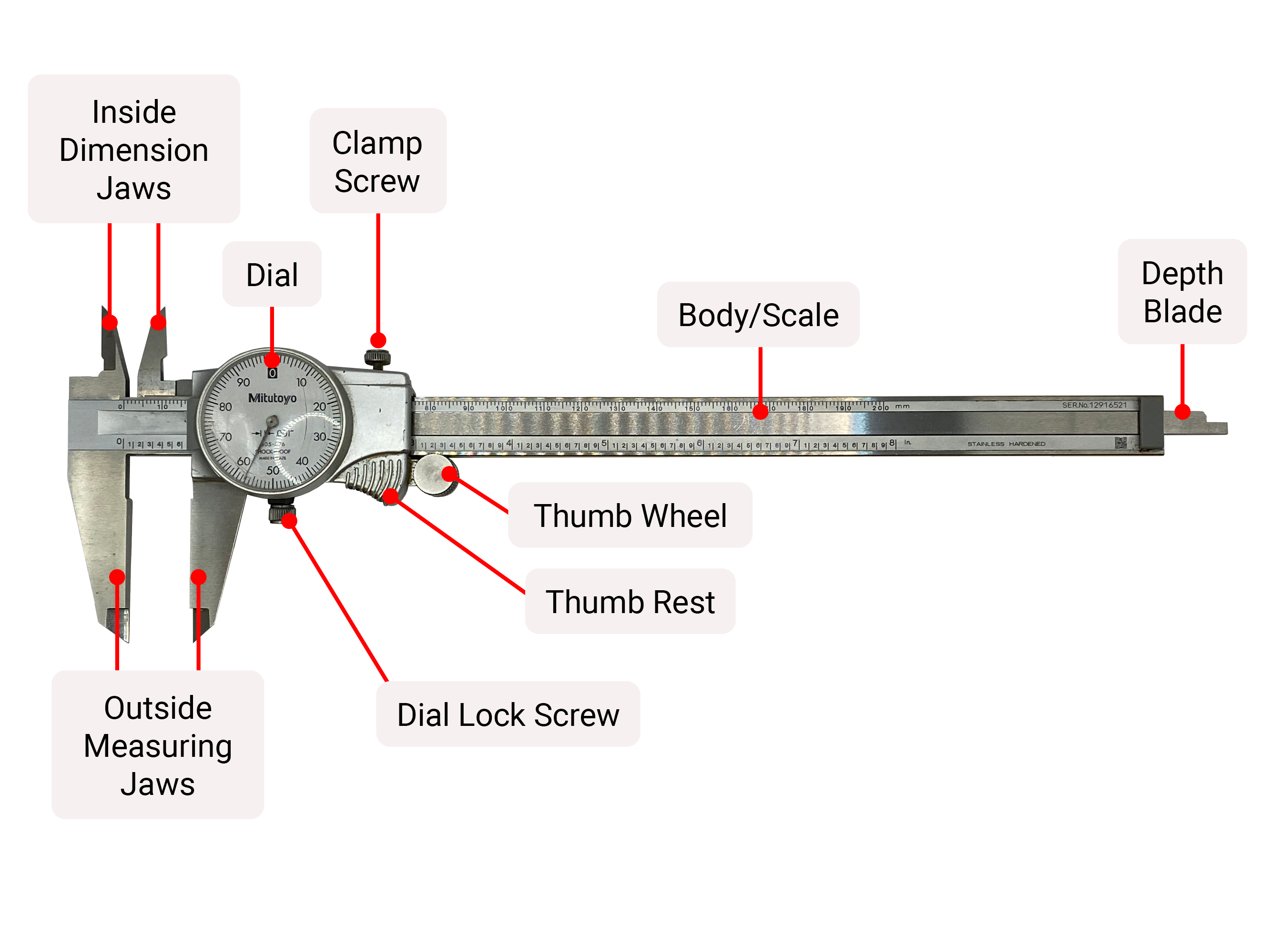
Precision slide calipers are the primary measuring tool in most machine shops. Their versatility, accuracy and ease of use make them the go-to instrument for many measurements. Calipers come in many sizes, with the 6″ being the most common. The three basic styles of slide caliper are vernier, dial, and digital, with the digital being most common.
Precision calipers all perform the same basic functions.
- Outside dimension (O.D.) a measurement performed on the outside of a part.
- Inside dimension (I.D.) a measurement performed on an inside feature of a part.
- Depth measurement
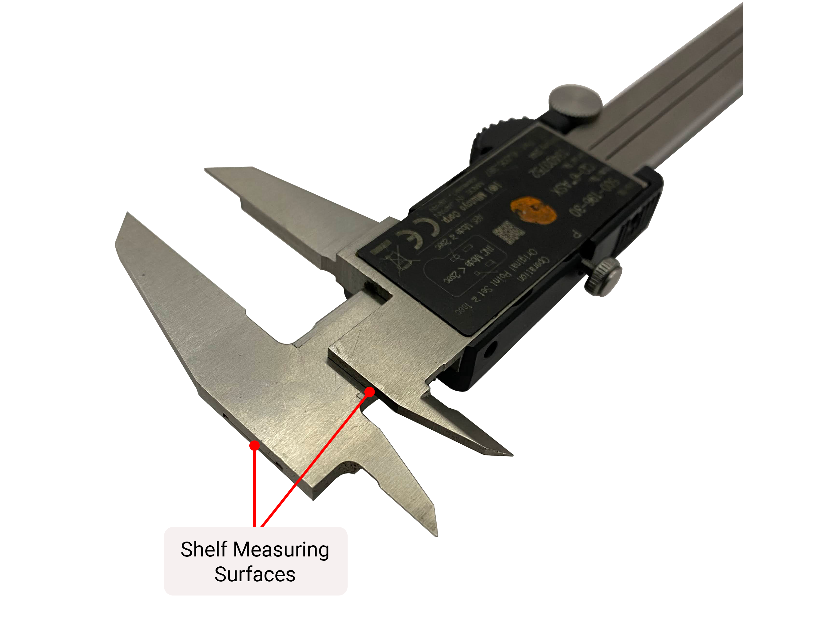
- Step/Shelf measurement

Pushing the OD jaws against the outside of an object and getting a quick reading is one of the most basic measurements you will perform with slide calipers.
When using slide calipers, there are some techniques to consider including ensuring the jaws are flat against the surface. If they are tilted, a larger measurement may be indicated and this would be inaccurate.
Similarly, you must apply only enough effort to close the jaws against the surface to be measured to ensure an accurate reading.
Using the round slide wheel provides some mechanical advantage, but this advantage comes with risk. To get a precise measurement, be careful not to apply excess pressure to the wheel when closing.

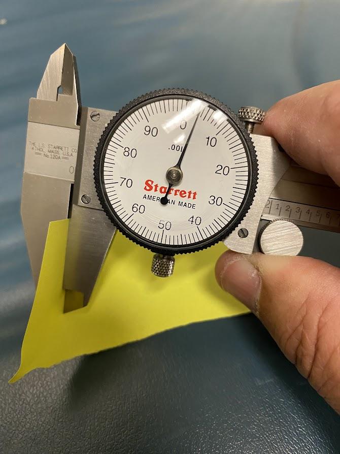
Figure 4.13. A slide caliper with carbide inserts on the outside measuring surfaces. / Image Credit: Damon Donner, CC BY 4.0The above digital caliper is a common brand and quality found in many machine shops. On this specific set, the OD faces are manufactured from carbide, creating a better wear surface as well as providing harder scribe points.
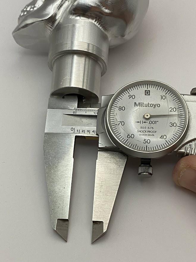
Above is demonstrating how the caliper can be used to measure the ID diameter of a hole. This is not an extremely accurate method to gage the inside diameter of a hole, but it can get you within a couple thou.
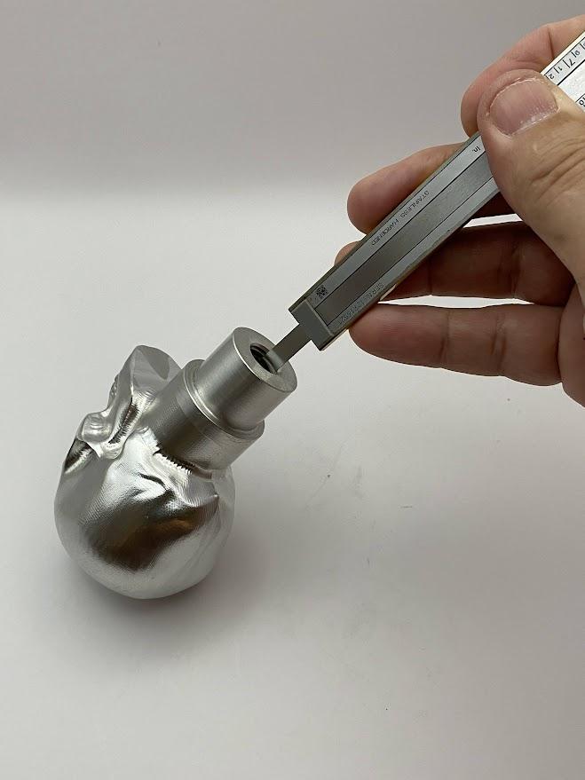
The Figure 4.15 illustrates that the depth probe can be used to measure a hole depth.
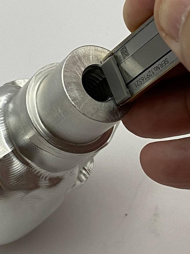
Once the depth probe reaches the bottom of the hole, slide the main scale until it contacts the surface of the hole. Now you can read the dial to get your dimension.
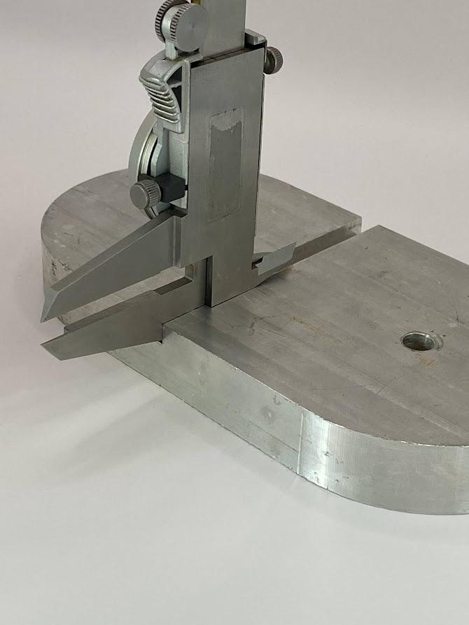
The step function of a slide caliper may be the least appreciated method for use; however, the slide caliper lends itself to this function very well. Ensure the caliper is perpendicular by pressing the flat surface of the stationary jaw against a surface.
You can use a 1-2-3 block to press against the caliper when needing a perpendicular relationship. In the photo above, the caliper beam is placed against the part and has a perpendicular relationship in one plane. The 1-2-3 block provides a secondary plane with a perpendicular relationship. This approach situates the measuring tool at the best placement for accurate measurement.
Caring for Slide Calipers
If you are using a piece of measuring equipment that has two parallel faces, those faces need to be cleaned on a regular basis during use to ensure error is mitigated.
Closing the jaws against a clean piece of paper is the quickest method. While applying light pressure against the paper, slide the paper out from between the jaws. This wipes away most contaminants that would alter the accurate reading.
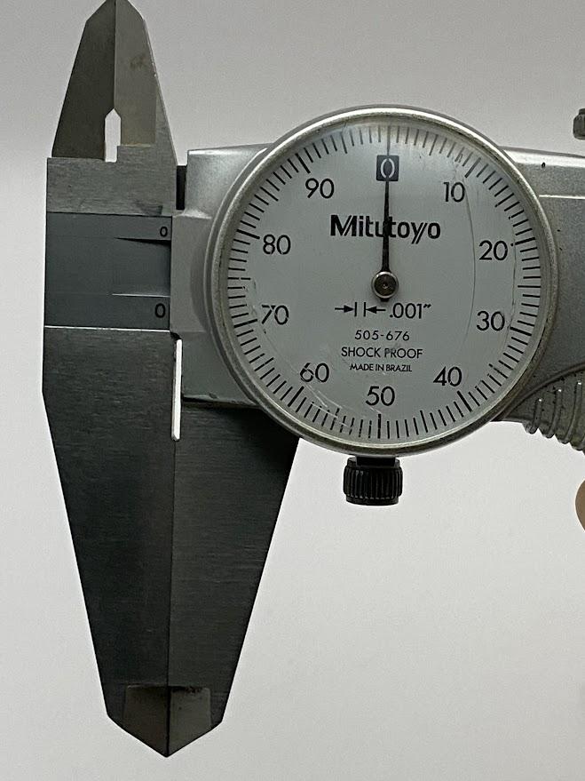
Now, with the jaws clean and closed to the zero position, look at the display to ensure a zero reading.
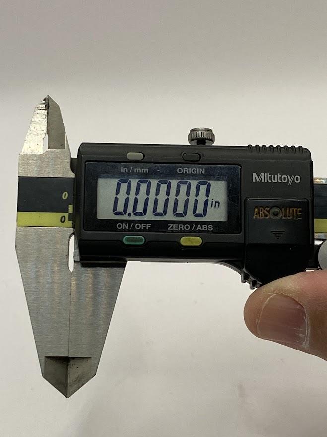
On a digital caliper, the indicator should display the “origin” on the scale. The origin is a zero-position set in a certifying process by someone qualified to calibrate measuring equipment.
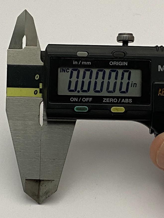
Now, let’s address the incremental (INC) on digital calipers.
A common mistake made by new machinists happens when verifying the zero on a digital measuring instrument. When the jaws are closed, and the digital display does not read zero, the operator might press the “ZERO/ABS” button changing the display to zero. Problem solved, right? NO! All this has done is negate the “origin” setting on the caliper. The origin is set when the battery has been replaced in a digital measuring device and the absolute (ABS) zero is set. For shops using a metrology program that places metrology stickers on the equipment, this process must be done by a qualified specialist who can verify the origin on a digital measuring device.
The above figure has an “INC” in the upper left corner, indicating this caliper is not in ABS mode and is using an incremental zero. Use of the incremental feature of digital measuring equipment will be explained below.

Contamination from the operators hands and the environment of a machine shop build up on caliper surfaces and inhibit smooth action. Regular maintenance is needed to clean the surfaces. A soft, lint-free cloth moistened with a mild solvent, such as alcohol, should be used to clean all accessible surfaces. Be careful to ensure excessive solvent does not seep into the encoder section of the caliper on digital calipers. Under the tape covering of the encoder section, the caliper beam contains an encoder strip which is read by a sensor inside the caliper body. Moisture will contaminate the encoder strip which can become evident during operation. The display will malfunction due to an inability to read a wet encoder.
Placing your fingers over both jaws and closing them over a surface to be measured gives you the advantage of “feeling” when the jaws are flat against the surface of the part. Most measurements require the operator to wiggle the part of the measuring device ever so slightly while applying closing force to the caliper. This subtle action ensures the caliper is not at an angle but rather is perpendicular to the measuring surface, which reduces parallax error. Parallax error is when a measuring device is placed at any angle, which negatively affects an accurate measurement.
Most calipers have an area on the sliding jaw with a texture that allows the thumb to push the sliding jaw of the caliper with little effort. This area is usually just in front of the slide wheel or in lieu of the slide wheel. By applying force here, the operator has a good “feel” for how much pressure is being applied. Feel is a skill learned over time with experience. Eventually you will become aware of subtle pressure on the pads of your fingers while performing delicate measuring operations. This subtle pressure and the proper technique of “wiggling” the tool while applying closing pressure will garner the most accurate measurements possible.
This method is the most popular, most likely due to the fact that the wheel is usually in the perfect place when using the caliper. Caution must be exercised when using this method because it is easy to apply unnecessary force with the mechanical advantage of the wheel.
Using the thumb wheel to adjust the jaws of a caliper is most advantageous when setting the jaws to a particular opening size before locking the jaws in place with the slide lock. This procedure is common when setting up a caliper to scribe a layout line on a part.
Once the desired width is reached, tighten the lock screw to prevent the jaws from moving.
Using Incremental on Digital Equipment
One advantage to using digital measuring equipment is its added versatility. Not only can you change the unit of measurement from inch to millimeter with the push of a button, but you can also set a temporary zero on the measuring equipment by pressing the “INC” button. This feature is designed to be used as a substitute zero and not to be used for the origin.
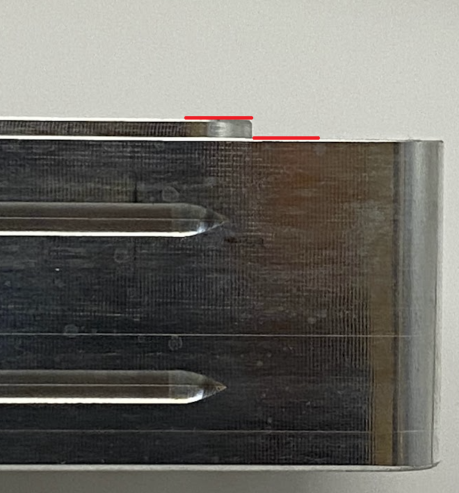
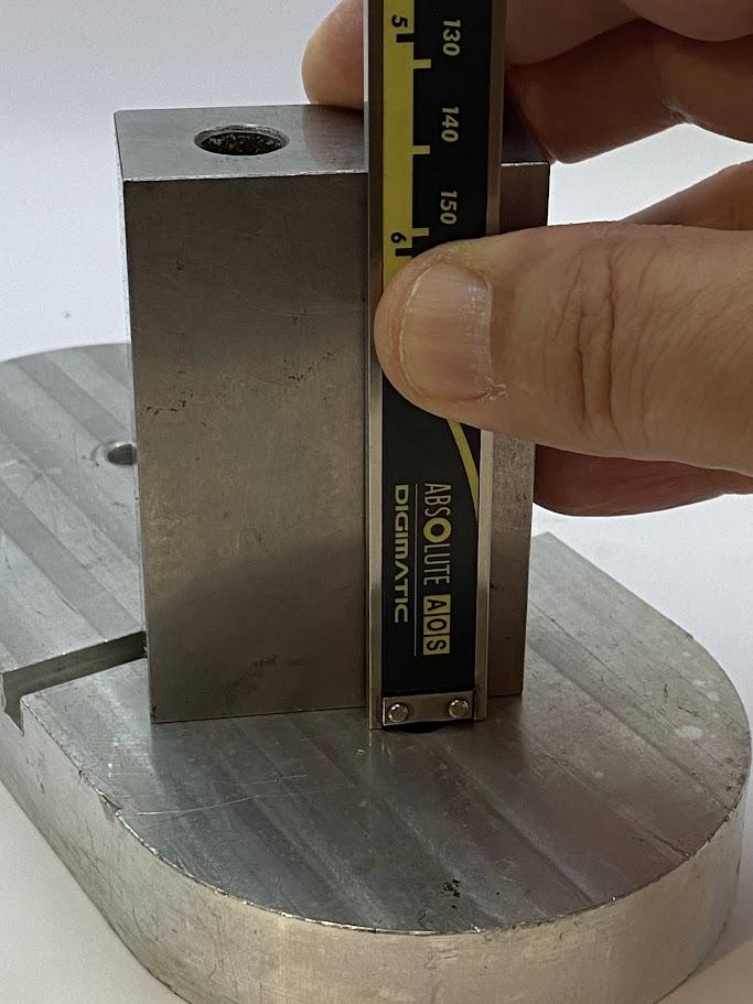
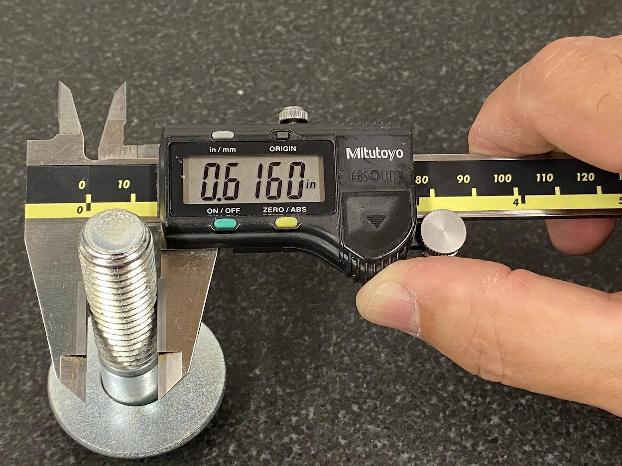
In the figure above, a machinist must measure the height difference between the two shelves. For ease of understanding, red lines have been added to identify the two shelf heights. The following steps will demonstrate how to measure this dimension by using the incremental function on a caliper. Note: the same method can be used on a digital micrometer or height gage.
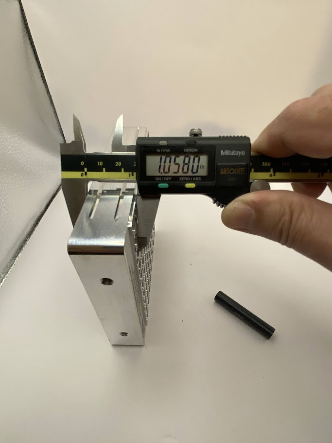
- Measure the larger dimension with the digital instrument.
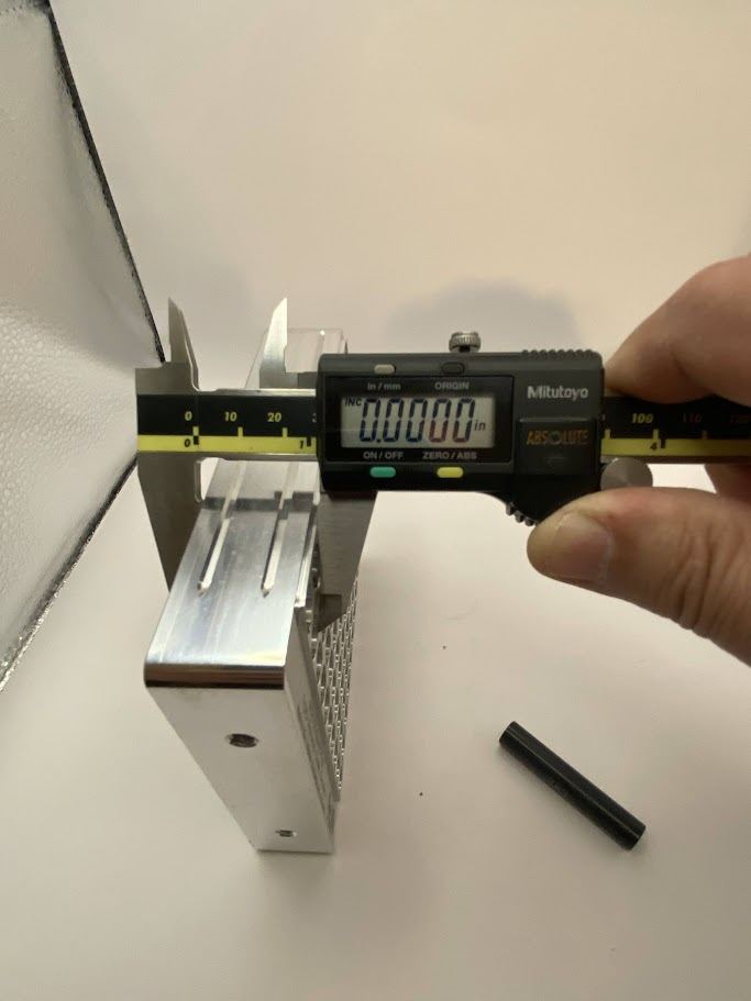
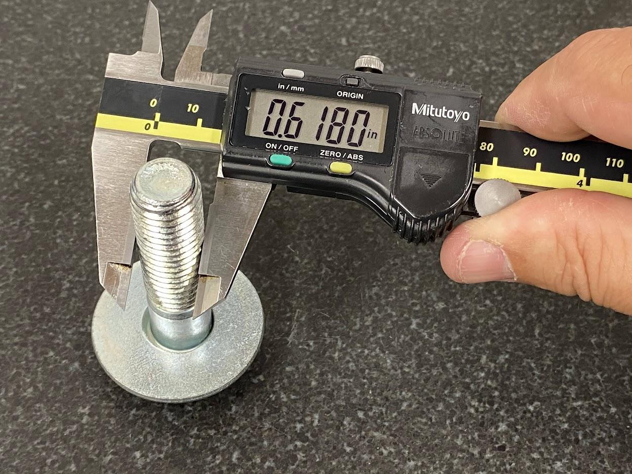
2. Press the ABS/INC button. This will establish a temporary zero. Note: the “INC” indicator is visible
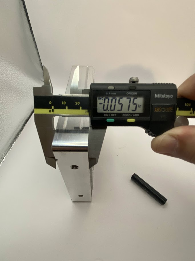
Figure 4.31. The caliper is closed on the shorter height of the part, and the display indicates .057”. /
Image Credit: Damon Donner, CC BY 4.0
3. Move the measuring device to the second shelf. The indicator now displays the difference between the two surfaces. This is the dimension needed to satisfy the inspection requirement.
4. Return the instrument back to the origin zero by pressing and holding the INC button until the indicator extinguishes.
In the next scenario, we need to measure the depth of a blind hole. Remember, a blind hole does not extend through the part. In this example, the hole has a shelf near the bottom of the hole, and we are going to measure the depth of the hole from the top of the hole to the depth of that shelf.
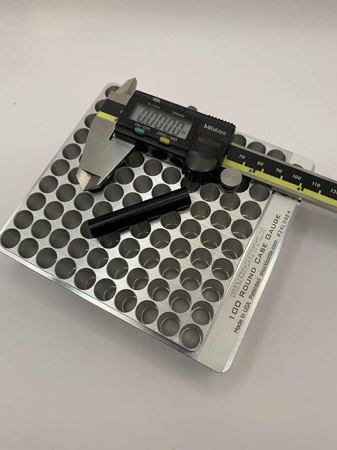
The tools necessary for this measurement are the digital caliper and an inspection pin of the correct diameter. In this case a .383″ pin was the largest pin that would contact the shelf within the hole.
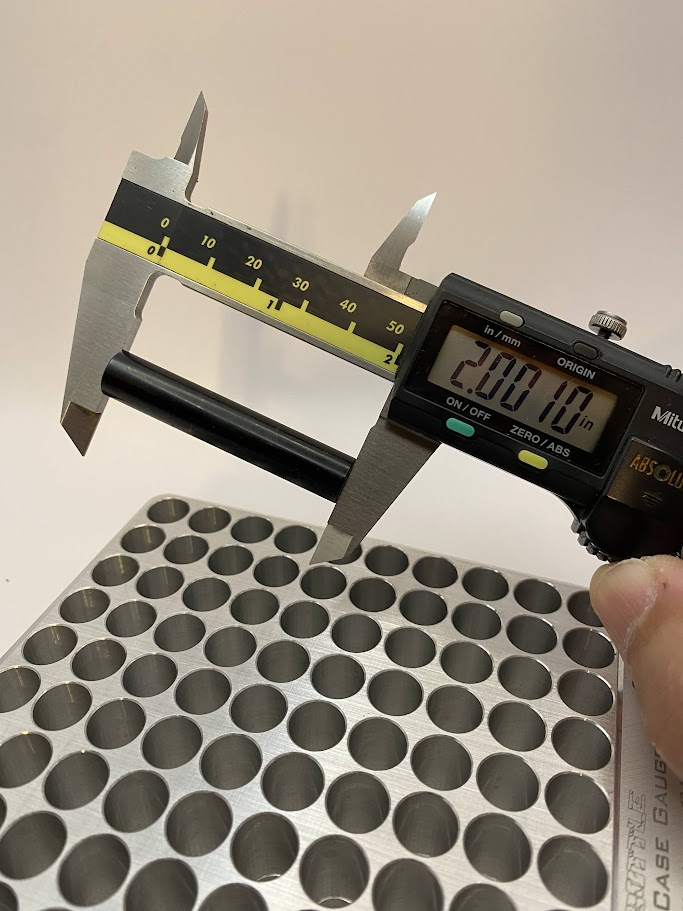
1.The first step is to close the caliper over the length of the pin. This pin measures just over 2.00″ in length. It is best to wiggle the pin while applying closing force on the caliper to ensure a good measurement.
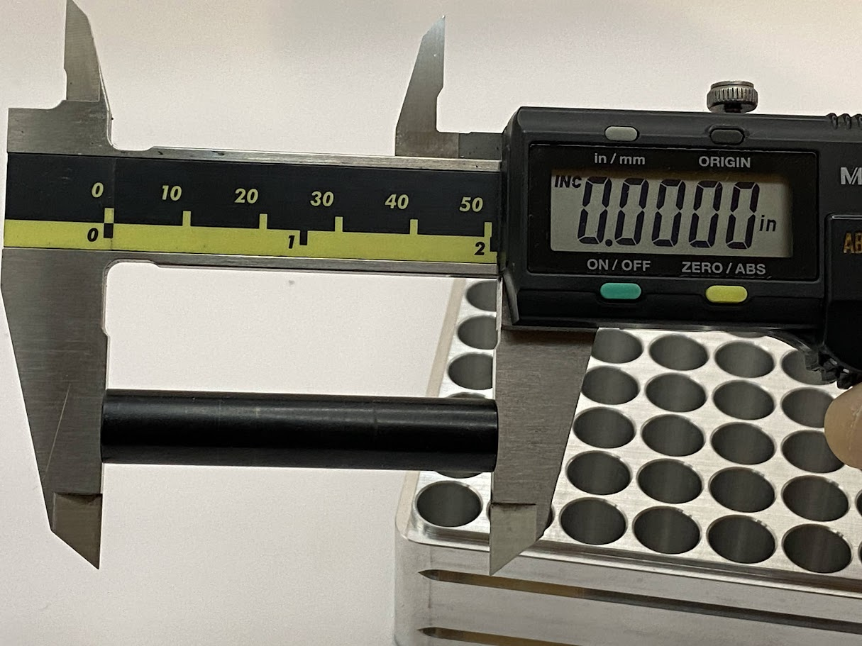
2. While holding the caliper tight against the pin, press the INC button to establish the incremental zero. In this case, the incremental zero is really 2.00″.
Holding the caliper against the pin while ensuring the end of the caliper is resting on the flat surface of the part is a critical technique to ensure the caliper remains perpendicular during the measuring process.
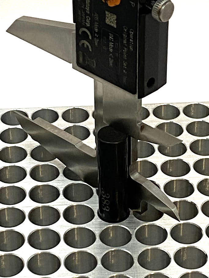
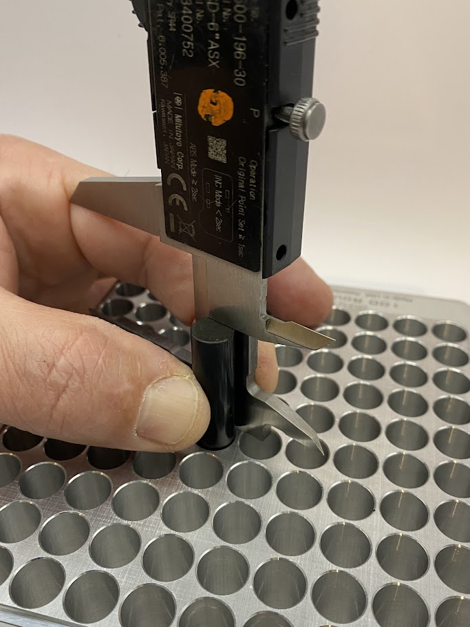
3. Using the height measuring feature of the caliper, measure the remaining height of the pin when the pin is placed in the hole and contacting the shelf.
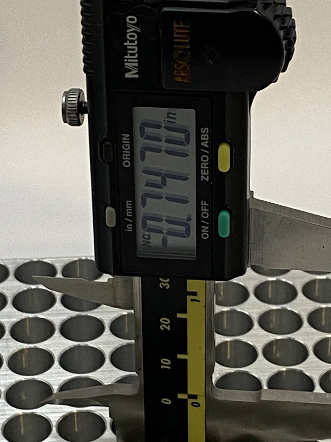
Figure 4.37. The reading on the display is the depth of the hole from the top surface to the shelf that the pin is resting against. The display on the caliper reads .747”. / Image Credit: Damon Donner, CC BY 4.0
4. While the caliper is being held in the above manner, read the display on the caliper. This is the depth of the hole from the top of the part to the end of the pin that is resting on the shelf. In our example, the depth of the hole from the surface to the top of the shoulder is .747″.
Outside Micrometers
Micrometer is a term used extensively in the precision machining industry, and it refers to a certain type of measuring equipment that is capable of extreme accuracy, usually in the tenths of a thousandth of an inch (.0001″). There are various types of micrometers designed to measure just as many types of dimensions, but we will discuss the most common types in this chapter.
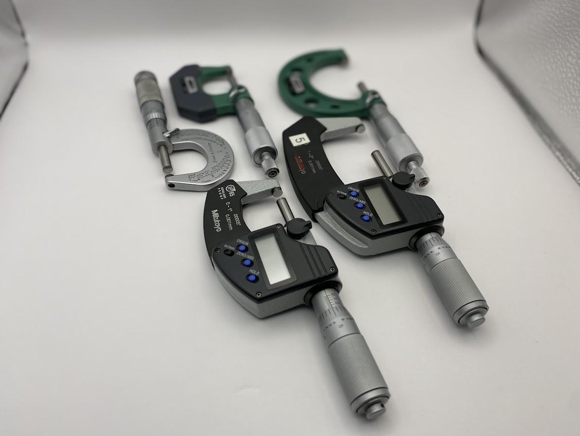
After the slide caliper, the Outside dimension (OD) micrometer, or just an “outside mic” is the next most common measuring tool. This tool allows the operator to measure dimension resolutions to ten thousandths (.0001) of an inch. Since the increment of precision measurements are in the thousandths range, mastery of this tool is paramount.

The most common micrometer or mic, is the 0-1″. With this micrometer, the spindle closes until it touches the anvil. This is the zero position and all operators must close the mic and verify zero before use.
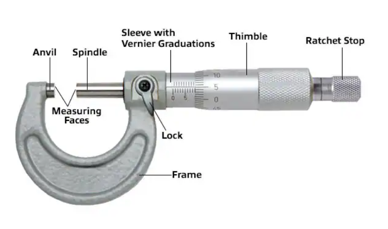
Key features and components of a micrometer include:
Frame: The frame is the main body of the micrometer. It typically consists of a C-shaped or U-shaped structure that houses the other components. It is common to have the frame clad with plastic to prevent the operator’s hands from transferring body heat into the measuring device. As noted earlier, heat may lead to inaccurate measurements.
Anvil and Spindle: The anvil and spindle are the two opposing, flat, and parallel surfaces between which the object being measured is placed. The anvil is stationary, while the spindle moves when measurements are taken. To preserve the flat relationship between the two mating faces, all micrometers should be stowed with a slight gap between the faces to account for thermal growth. Thermal growth can damage the faces.
Sleeve: The sleeve is the cylindrical portion of the frame that contains the barrel and the thimble. It usually has a graduated scale, often marked in millimeters (mm) or inches (in) to provide a coarse measurement.
Thimble: The thimble is located at the end of the barrel and can be rotated to move the spindle incrementally. It has a circular scale, typically divided into 25 or 50 divisions, representing one full rotation of the spindle. The thimble is turned to open and close the micrometer. A ratchet stop may be attached to the back of the thimble. The operator gently closes the micrometer onto the part, twisting the ratchet while seating the micrometer with delicate wiggling to set the faces against the measured surface. On some models, the thimble has a clutch under it which serves a similar purpose to the ratchet stop. The ratchet stop will click while turning, and the clutch thimble will slip, preventing the operator from over-torquing the micrometer and obtaining an inaccurate measurement.
Spindle Lock: As the name implies, the spindle lock prevents the spindle from turning. This can be used to maintain the position of the micrometer faces while the operator reads the measurement. On a digital micrometer, it is essential for the operator to lock the spindle before storing the micrometer. This action prevents the digital micrometer’s “turn to wake” function from energizing the circuits when the tool gets bumped resulting in dead batteries.

Figure 4.42. The digital display of a measuring device has a low battery symbol illuminated. / Image Credit: Damon Donner, CC BY 4.0To use an outside micrometer, an object to be measured is placed between the anvil and the spindle. The thimble is then rotated, causing the spindle to move toward the object until it makes contact. The graduations on the barrel and thimble scales, or reading the digital display are used to read the measurement. The barrel scale provides the coarse measurement in millimeters or inches, while the thimble scale provides the finer measurement in micrometers or thousandths of an inch.
Operation of a Micrometer
Preoperational Inspection
Before using a micrometer to take a measurement, the operator must ensure the micrometer is ready to perform the task accurately. This is done by conducting a preoperational inspection of the micrometer. There are many factors that influence whether a micrometer can accurately measure a dimension. First, remove the micrometer from the protection of the storage case and visually inspect the components for dents, scratches, misalignment or any signs of abuse. In shops that utilize calibration programs, there should be a calibration sticker on the equipment with a date showing when the next inspection is due. Verify that the inspection date is still valid.

After the visual inspection, the faces of the spindle and anvil must be cleaned to remove surface contaminants that accumulate during normal use. The surfaces are wiped with a clean piece of paper.
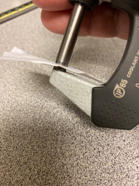
Using a clean piece of paper, gently close the micrometer onto the paper and give the thimble clutch a couple of turns. Pull the paper free from between the jaws, transferring the contaminants from the faces onto the slip of paper. Repeat as necessary.
Zero the Indicator
Once the faces of the spindle and anvil are clean, gently close the micrometer until the faces touch (0-1″ micrometer). Give the thimble a couple of turns, simulating the action used to perform an accurate measurement, and verify that the display reads zero. DO NOT press the ” ZERO/ABS” button to zero the micrometer, as this can lead to inaccurate measurements.
If the micrometer indicates a good zero after performing these steps, you may start performing measurements.
If a good zero can not be obtained using the above methods, the micrometer should be removed from service and repaired/calibrated by qualified individuals.

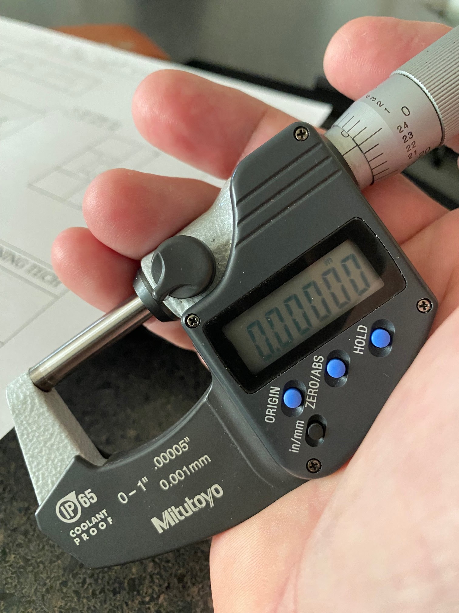
Figure 4.47. The digital display of a zero to one inch micrometer indicates zero and the “INC” indicator is illuminated./ Image Credit: Damon Donner, CC BY 4.0
Absolute Zero/Origin: On quality equipment, the absolute “zero” is set by the metrology lab when calibrating the micrometer and is referred to as the “origin”. Understanding that the origin is the absolute zero is critical to proper use of a micrometer. As an operator, you must ensure the micrometer references the absolute zero before making a measurement.
On this Mitutoyo brand micrometer, the origin button is on the face of the dial. This button is only to be used by the metrology lab. Never press the origin button as this will void the calibration of the micrometer.
The “ZERO/ABS” feature is used by the operator to switch between incremental and absolute mode. This feature allows the operator to set an incremental zero, which is useful for making comparative measurements, when an absolute measurement is not necessary.
Part of the preoperational inspection of a digital micrometer is to verify the micrometer is NOT in the incremental mode. Notice Figure 4.47 above. The “INC” displayed denotes that the micrometer is NOT using the origin (“ABS” or Absolute) zero but rather an incremental zero. To set the micrometer back to absolute mode on this micrometer, the “ZERO/ABS” button is pressed and held until the “INC” flag is extinguished.
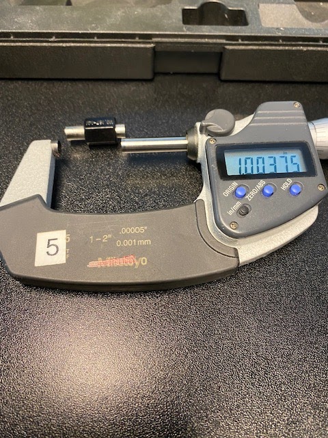
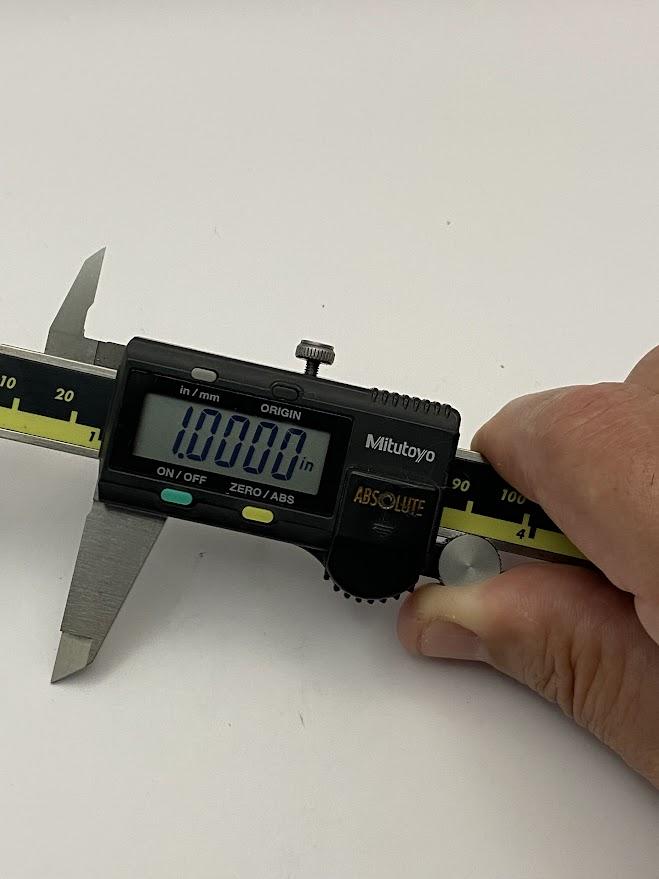
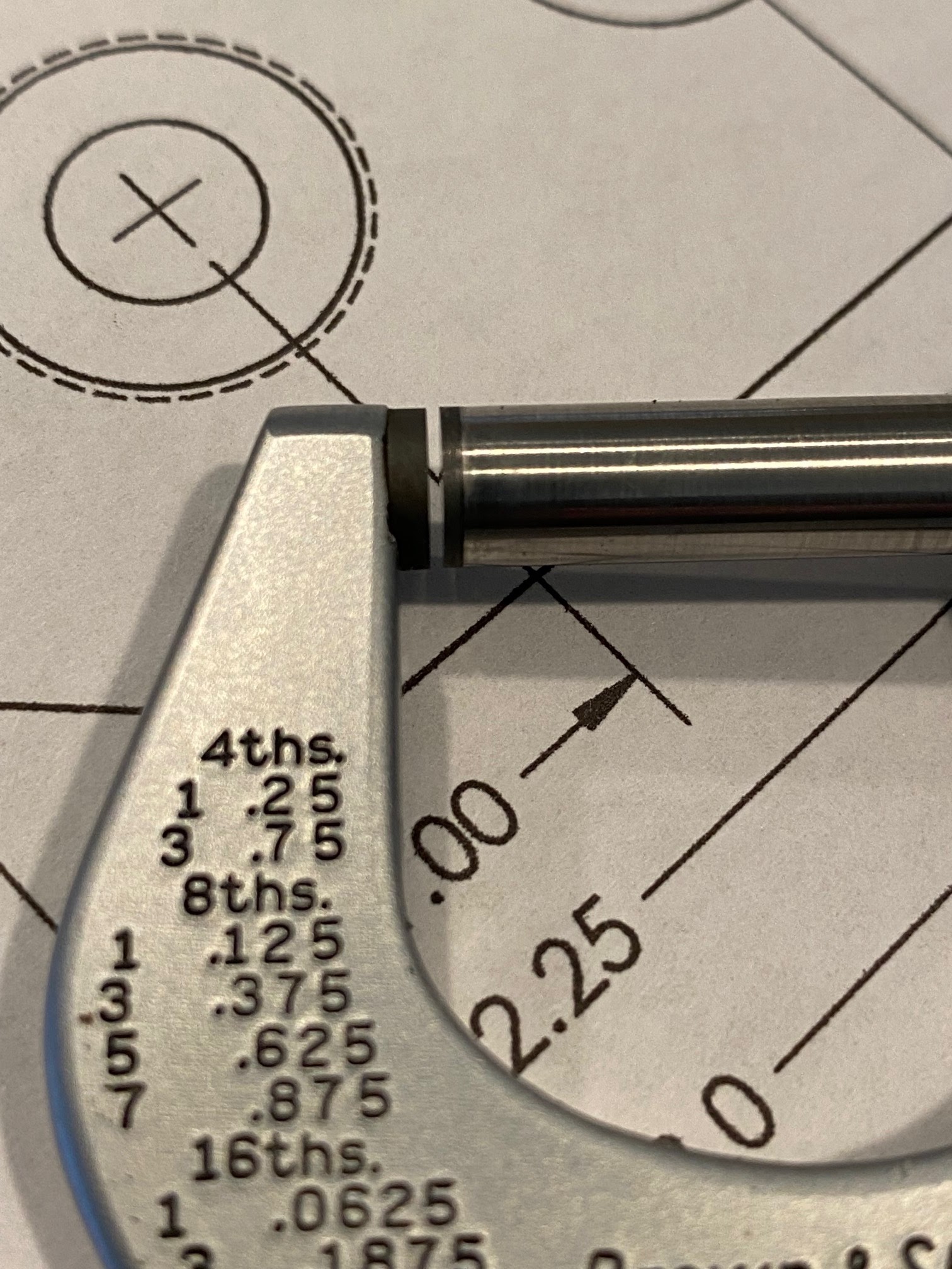
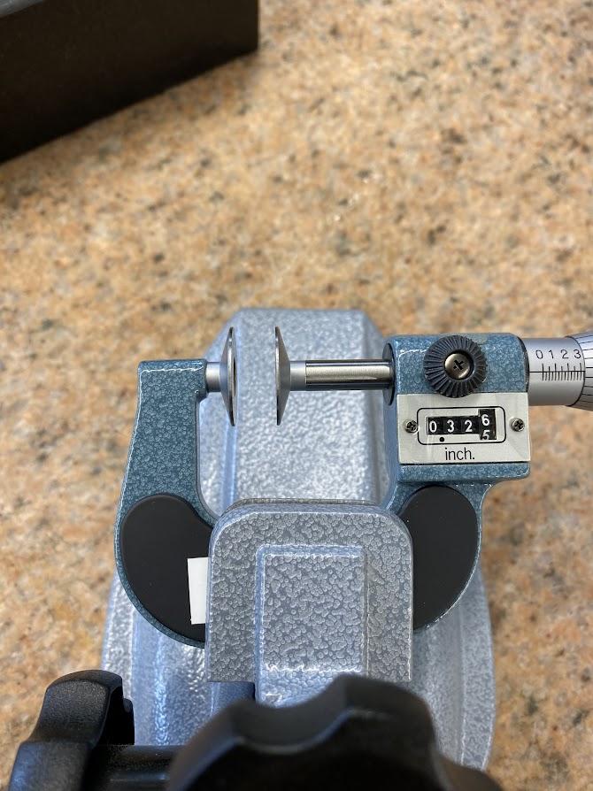
Micrometers generally have one inch of travel. On a 0-1″ micrometer, the spindle and anvil can touch, allowing a zero/origin to be verified. On larger micrometers, such as the 1-2″ micrometer above, we need to use an inspection standard to verify the equipment zero. An inspection standard is a piece of equipment with a calibrated size that is used to check other pieces of inspection equipment.
Measuring with a micrometer.
After the micrometer passes a thorough preoperational inspection, you are now able to perform accurate measurements.
To perform an accurate measurement with a micrometer, you need to open the micrometer larger than the dimension to be measured. This is done by rotating the thimble counterclockwise. Before closing the micrometer on the object, ensure the area is free of oil and debris. Any contamination on the measured surface will add error to the measurement. For high tolerance dimensions, less than .001″, allow the part to cool before measuring, as the excess heat will cause the part to expand and throw off the measurement.
The shape of the micrometer frame rests in the hand naturally, with the back nestled in the palm of your hand. The fingertips support the open side of the micrometer and twist the thimble which moves the spindle either in or out. This is a good time to mention the pressure you should feel in your fingertips. Measuring is a delicate process that utilizes feedback from the pads of the fingers to indicate how much pressure you are applying.
With the micrometer open enough to allow a close fit over the part, place the anvil against one side of the part to be measured.
Turn the spindle to close (clockwise) using the thimble until the spindle face nears the part. Slowly turn the thimble until the spindle face gently touches the part.

Once both faces of the micrometer are in contact with the part, gently wiggle the micrometer while turning the thimble or ratchet if applicable. This action helps to seat the faces securely against the part eliminating any angular differences between the faces and the part. You can now take a reading. Pressing the hold button will lock the reading, preventing the display from changing due to operator movement. The brake may also be applied at this point to perform the same purpose as the hold button.
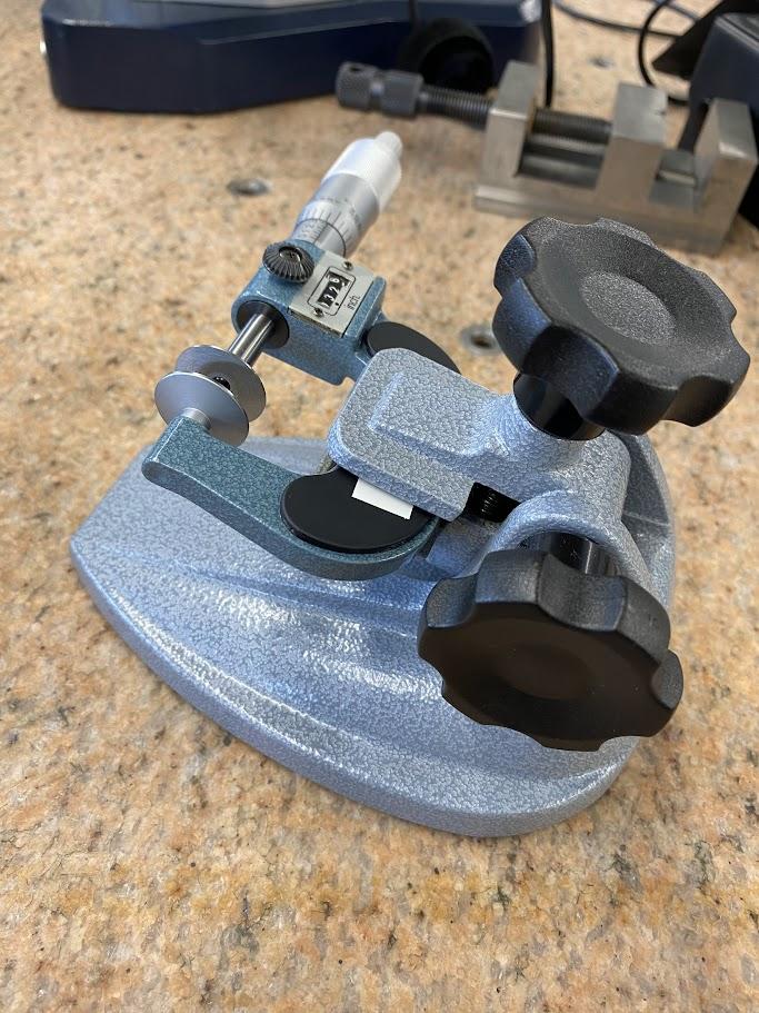
Micrometer Accessories

For some jobs, there are never enough hands. That’s when a micrometer stand comes in handy. The mic stand is a clamping device which has an adjustable hinge to present the mic at a convenient angle for reading.
The figure above has a mechanical digital disc micrometer clamped in a mic stand. This is what passed for digital before electronic versions became widespread.
Reading a vernier micrometer
The vernier scale has an advantage due to its basic design, which does not require the use of batteries (which always seem to lose charge at inconvenient times). Vernier measuring equipment is more difficult to read compared to digital tools which require only reading the display. They are included here because you will find them in industry right alongside their digital counterparts.
Reading in thousandths of an inch, .001
Starrett is a prominent US manufacturer of precision measuring equipment, and they provide online access to their catalogs.
Below are detailed instructions on how to read the micrometer in thousandths of an inch, from the Starrett Corporation’s Operations Procedures for micrometer operation (2014):
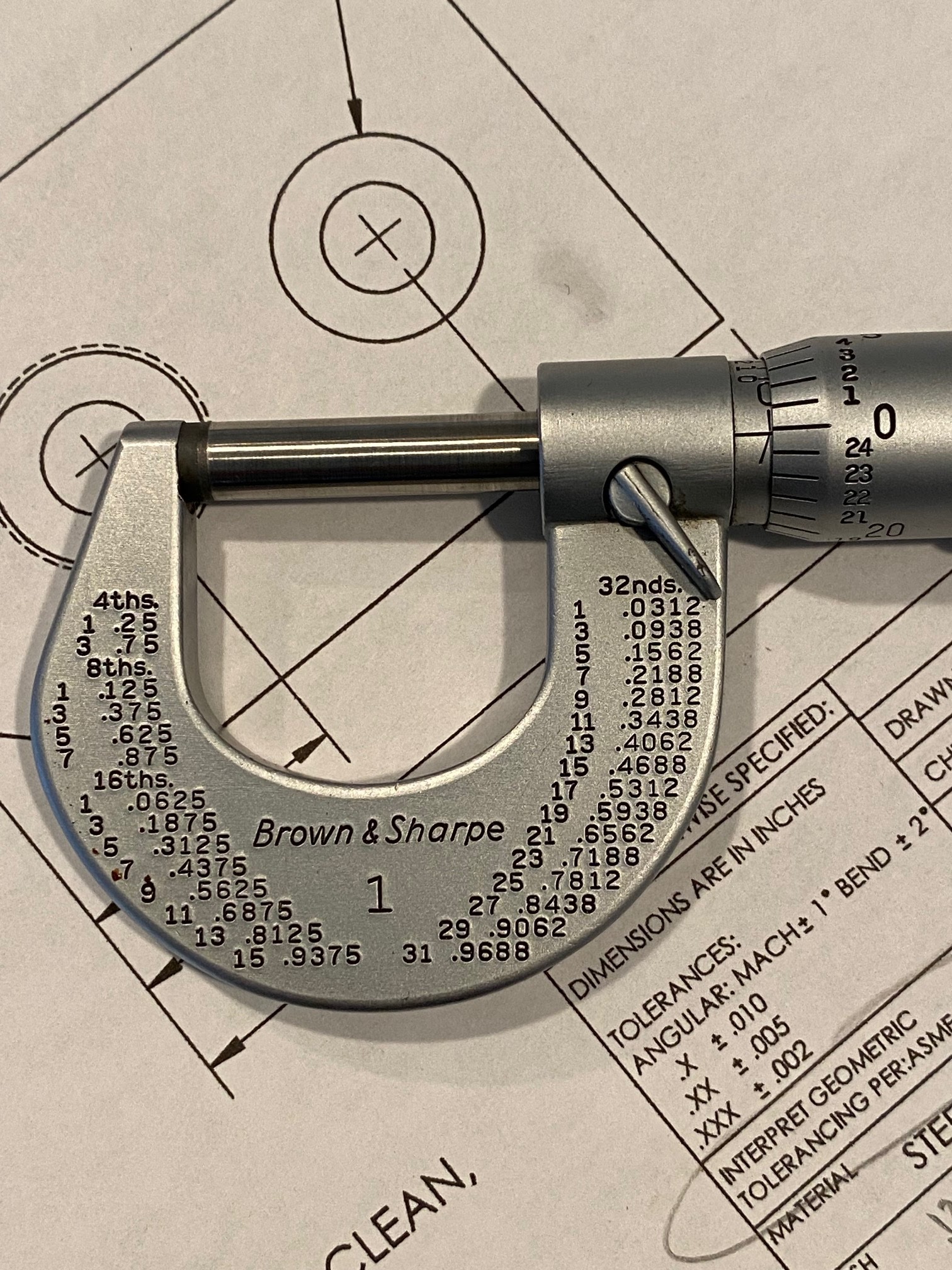
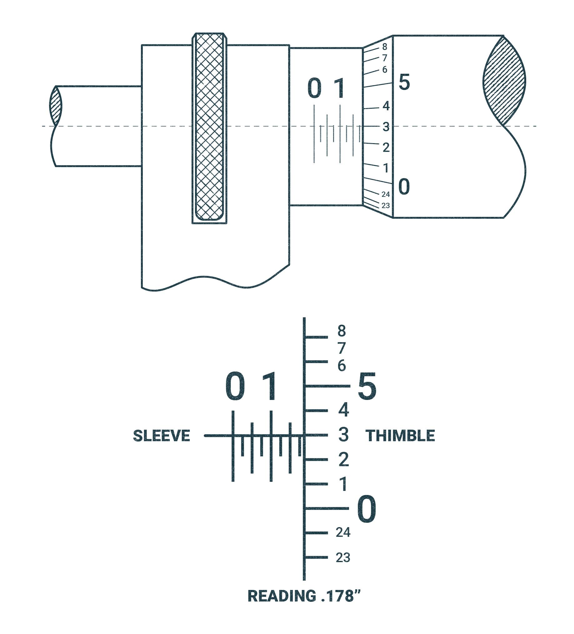
The pitch of the screw thread on the spindle is 40 threads per inch. One revolution of the thimble advances the spindle face toward or away from the anvil face precisely 1/40″ or .025 inches. The reading line on the sleeve is divided into 40 equal parts by vertical lines that correspond to the number of threads on the spindle. Therefore, each vertical line designates 1/40″ or .025 inches. Lines vary in length for easy reading. Every fourth line, which is longer than the others, designates a hundred thousandths. For example: the line marked “1” represents .100″ and the line marked “2” represents .200″, etc. The beveled edge of the thimble is divided into 25 equal parts with each line representing .001″ and every line numbered consecutively. Rotating the thimble from one of these lines to the next moves the spindle longitudinally 1/25 of .025″, or .001″. Rotating two divisions represents .002″, etc. Twenty-five divisions indicate a complete revolution of .025″ or 1/40 of an inch. To read the micrometer in thousandths, multiply the number of vertical divisions visible on the sleeve by .025″, and to this add the number of thousandths indicated by the line on the thimble that coincides with the reading line on the sleeve. (p. 22)
Reading in the ten-thousandths of an inch, .0001
Below are detailed instructions on how to read the micrometer in the ten-thousandths of an inch, from the Starrett Corporation’s Operations Procedures for micrometer operation (2014):
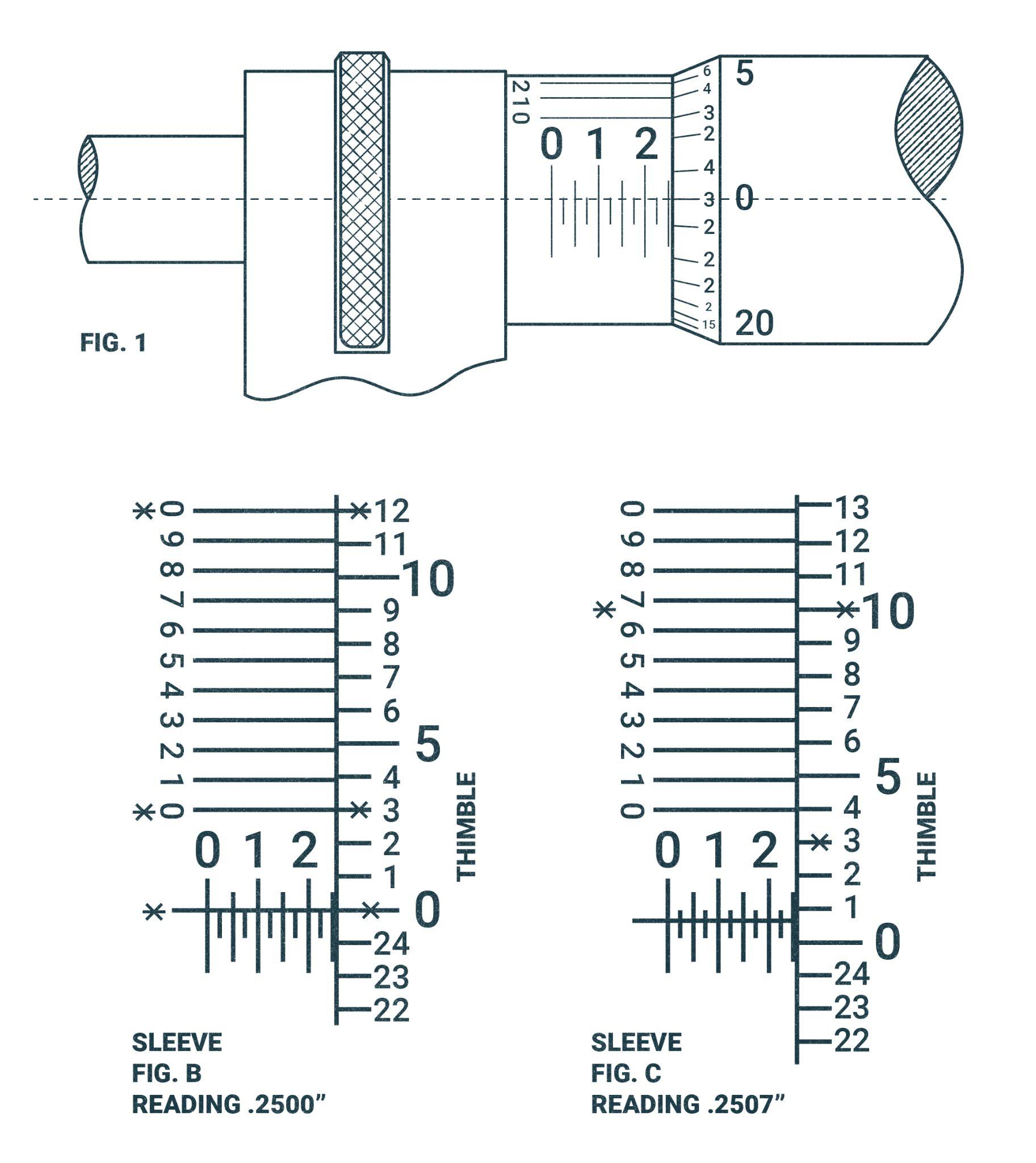
Micrometers graduated in ten-thousandths of an inch read like micrometers graduated in thousandths, except that an additional reading in ten-thousandths is obtained from a vernier scale on the sleeve. The vernier consists of ten divisions on the sleeve, which occupy the same space as nine divisions on the thimble (Fig. B). Therefore, the difference between the width of one of the ten spaces on the vernier and one of the nine spaces on the thimble is one-tenth of a division on the thimble, or one ten-thousandth (.0001″). To read a ten-thousandths micrometer, first obtain the thousandths reading, then see which of the lines on the vernier coincides with a line on the thimble. If it is the line marked “1” on the sleeve, add one ten thousandth, if it is the line marked “2”, add two ten-thousandths, etc. (p. 22)
Reading in hundredths of a millimeter, 0.01mm
Below are detailed instructions on how to read the micrometer in the hundredths of a millimeter, from the Starrett Corporation’s Operations Procedures for micrometer operation (2014):
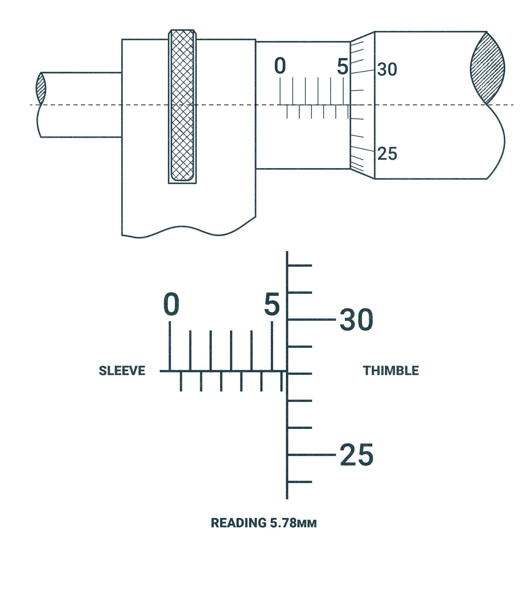
The screw head pitch is one-half millimeter (0.5mm). One revolution of the thimble advances the spindle face toward or away from the anvil face precisely 0.5mm. The reading line on the sleeve is graduated above the line in millimeters (1.0mm) with every fifth millimeter being numbered. Each millimeter is also divided in half (0.5mm) below the reading line. Two revolutions of the thimble advance the spindle 1.0mm. The beveled edge of the thimble is divided into fifty equal parts, with each line representing 0.01mm and every fifth line being numbered. Rotating the thimble from one of these lines to the next moves the spindle longitudinally 0.01mm; rotating two divisions represents 0.02mm, etc. To read the micrometer, add the number of millimeters and half-millimeters visible on the sleeve to the number of hundredths of a millimeter indicated by the thimble graduation indicated by the reading line. (p. 23)
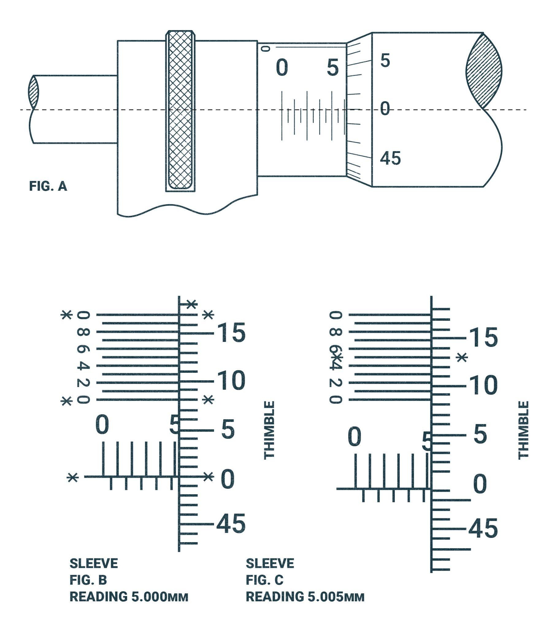
4.3.4.8 Reading in thousandths of a millimeter, 0.001mm
Below are detailed instructions on how to read the micrometer in the thousandths of a millimeter, from the Starrett Corporation’s Operations Procedures for micrometer operation (2014):
Reading a 0.001mm micrometer is exactly like reading a 0.002mm micrometer except that there are ten divisions on the vernier occupying the same space as nine divisions on the thimble (Fig. B). Therefore, the difference between the width of one of the spaces on the vernier and one of the nine spaces on the thimble is one-tenth of a division on the thimble, or one-thousandth (0.001mm). First obtain the hundredth of a millimeter (0.01mm) reading. Next, see which of the lines on the vernier coincides with a line on the thimble. If it is the first line add 0.001mm to the reading, if it is the second line add 0.002mm, etc. Only every second vernier line is numbered on a 0.001mm reading tool because of space congestion. (p. 23)
Blade Micrometers
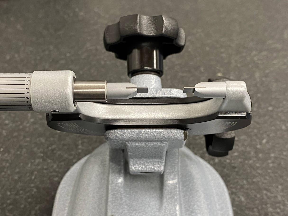
The blade micrometer is primarily used to measure grooves. Grooves are common in industry to create space for an o-ring or other sealing device to create a seal between a piston and a cylinder bore. A bore is a female cylindrical feature.
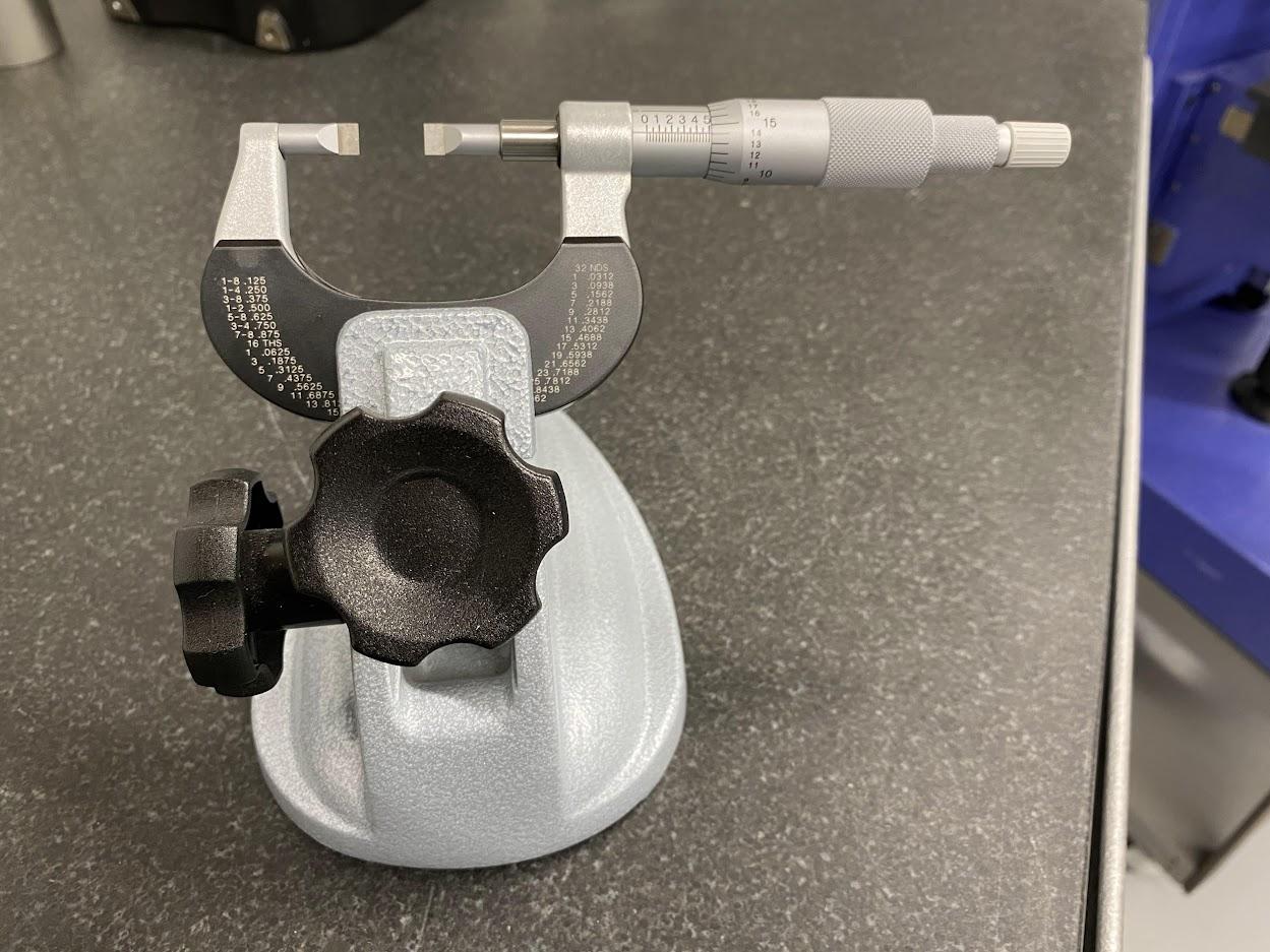
As noted in the pictures above, the only difference is that the blades have replaced the flat anvil and spindle faces of traditional OD micrometers. The blade micrometer above makes use of a small diameter knob on the end of the thimble. Its purpose is to allow the operator the ability to rapidly advance the thimble when making large movements on the scale. Once the micrometer nears the final dimension, the operator would transition to the larger thimble knob for the delicate final adjustments.
Disc Micrometer
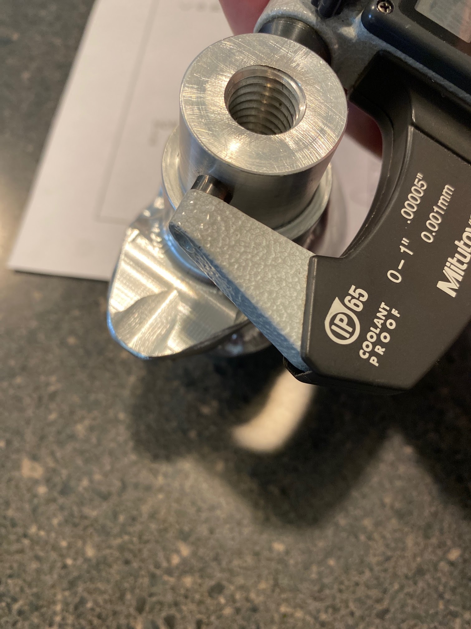
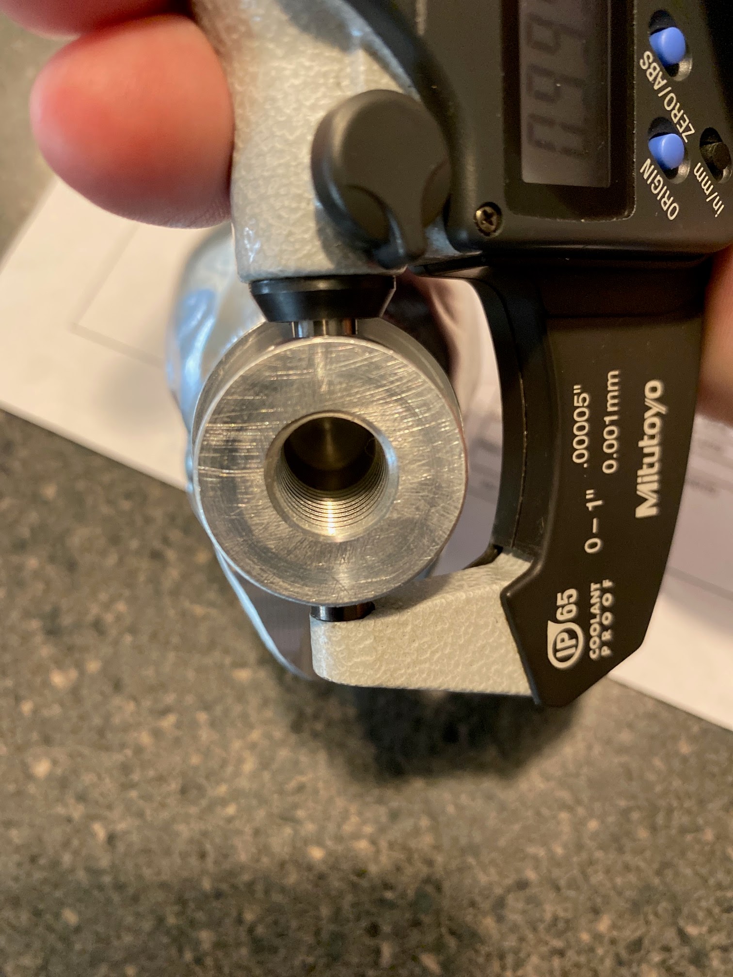
The disc micrometer is another OD micrometer designed for more specific purposes. The discs protrude out beyond the range of the standard anvil/spindle faced micrometers. This design allows for precision measurement provided by the micrometer’s resolution for tighter tolerance dimensions.
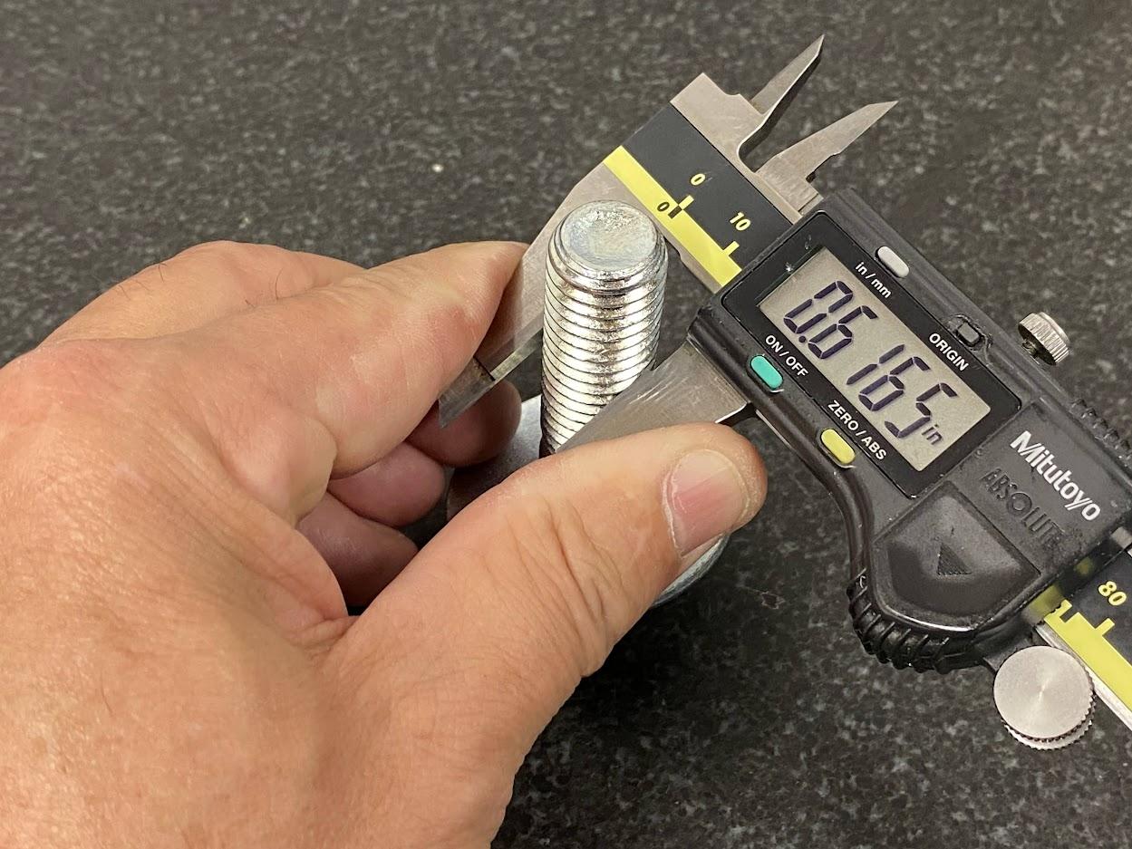
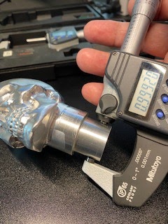
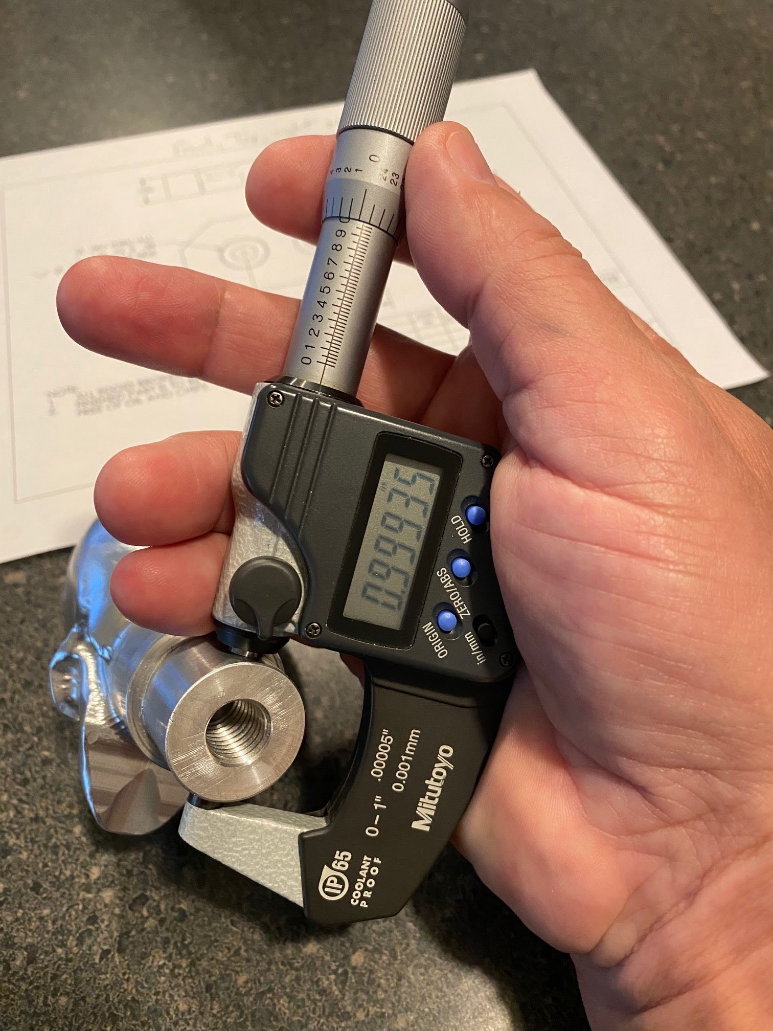
Above: the disc micrometer is used to measure the diameter of a stud with a resolution of .0001″.
Thread Micrometer
Thread micrometers measure the pitch diameter on external threads. They come with a selection of anvils to allow the measuring of different thread pitches.
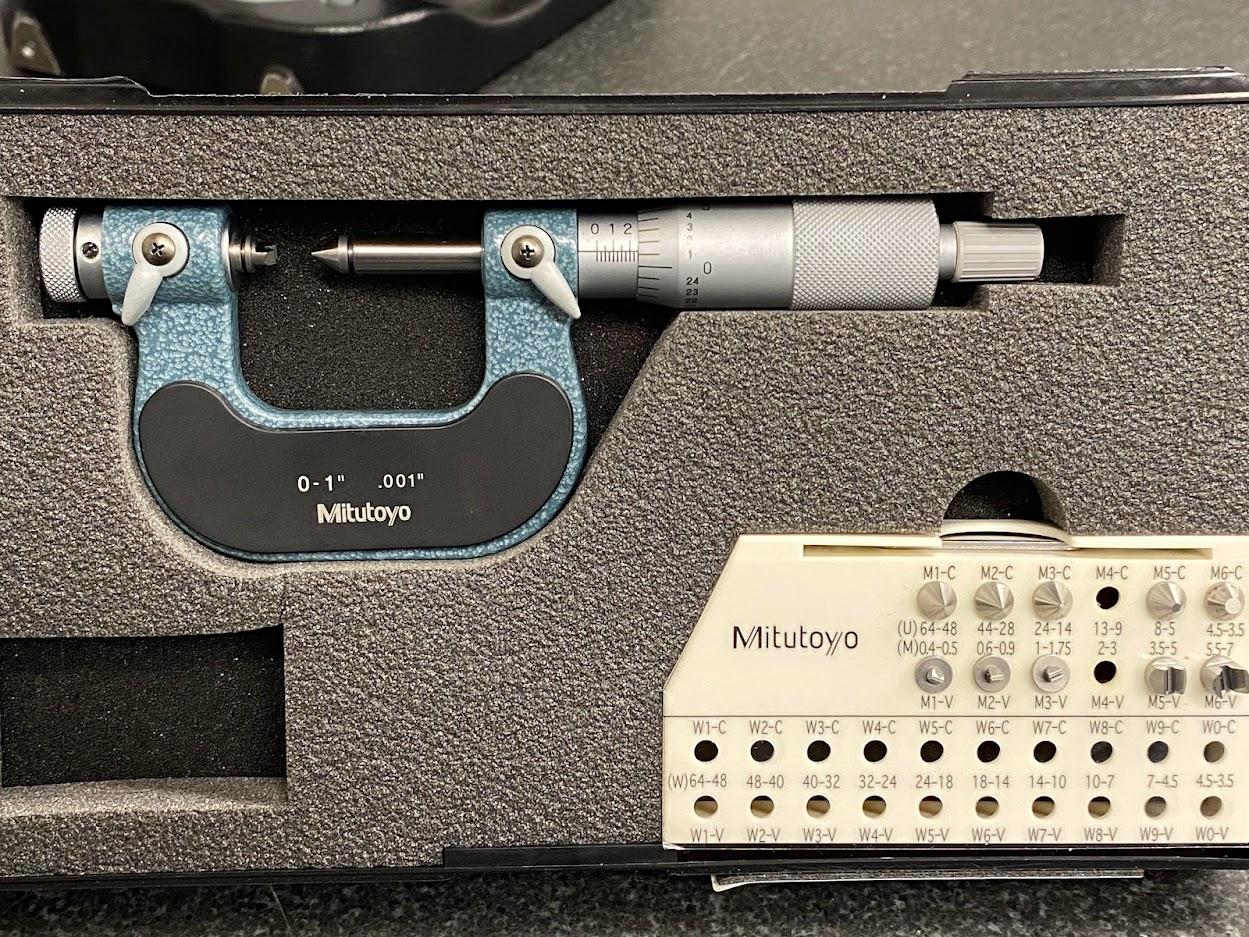
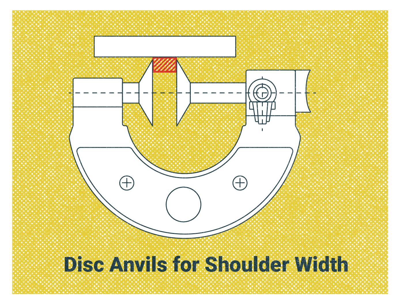
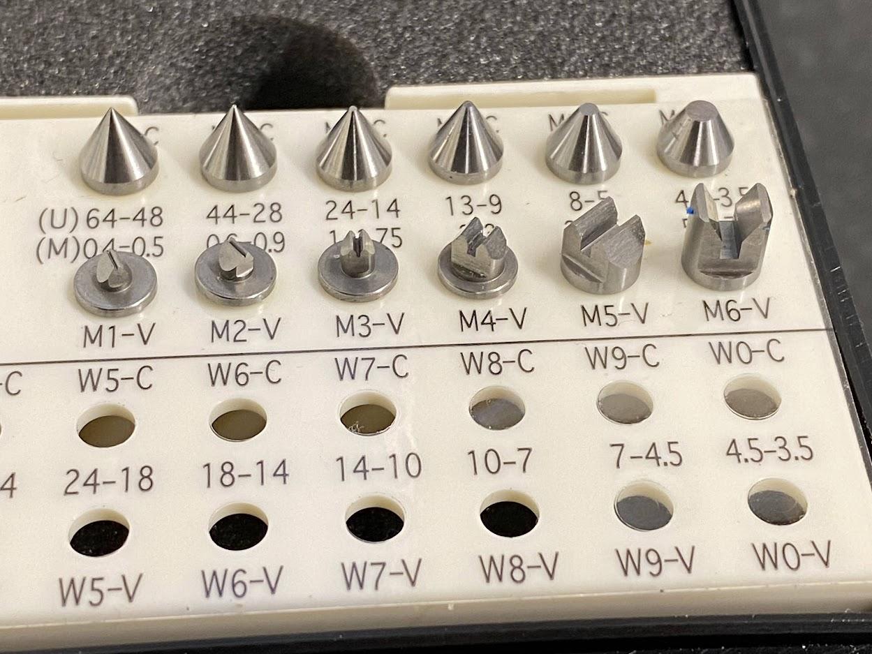
A thread micrometer set comes with a mic body which is used to determine the maximum major diameter allowed. The set also includes a selection of paired conical and V-style anvils. Anvil choice is dependent upon pitch of the thread. Note the range displayed near the top row of conical anvils in Figure 4.64.
The anvils cover both Unified Standard (U) and Metric (M) threads. In the photo above, the anvils used to measure a ½-13 UNC thread are missing from the case because they are installed in the micrometer.
Two anvils are required to measure a thread, one conical (cone shaped) and one V-style.
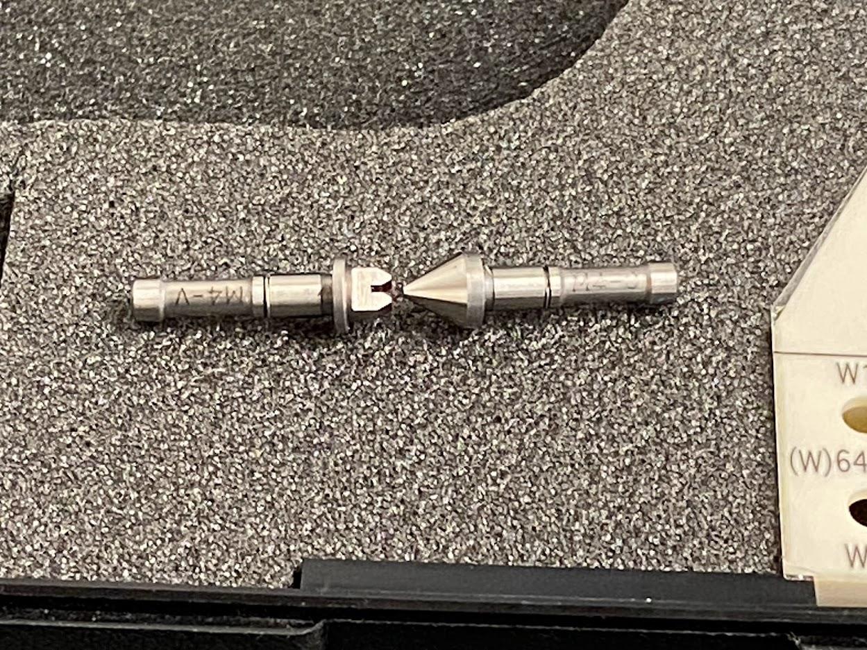
The photo above provides a better view of the anvils for a thread mic. They are precision ground and provide a tight fit in the micrometer body.
Thread Micrometer Operation
Start by selecting the set of anvils that correspond to the pitch of the thread. For a ½-13 UNC thread, select the 13-9 anvils.
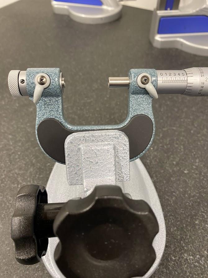
Open the micrometer to allow room to install the anvils.
The thread micrometer adjusts to the various anvils that may be installed. The stationary anvil socket allows the operator to set the mic to zero with any of the anvils.
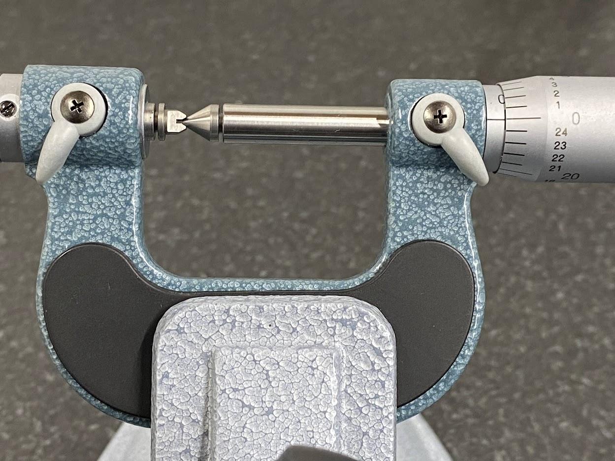
To use the mic, first, turn the spindle until the zero is reached. Then, apply the spindle lock to prevent movement.
Next, loosen the stationary anvil’s socket and turn the knob until the two anvils touch.
Apply the stationary anvil brake, and loosen the spindle brake to open and measure threads.
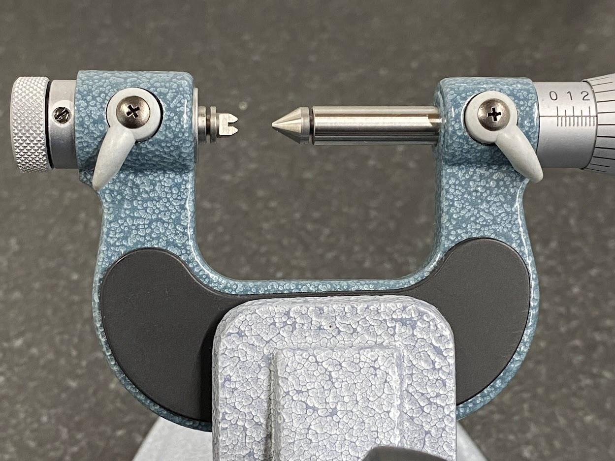
Insert the anvils into the mic with the conical anvil in the spindle, and the V-anvil in the base.
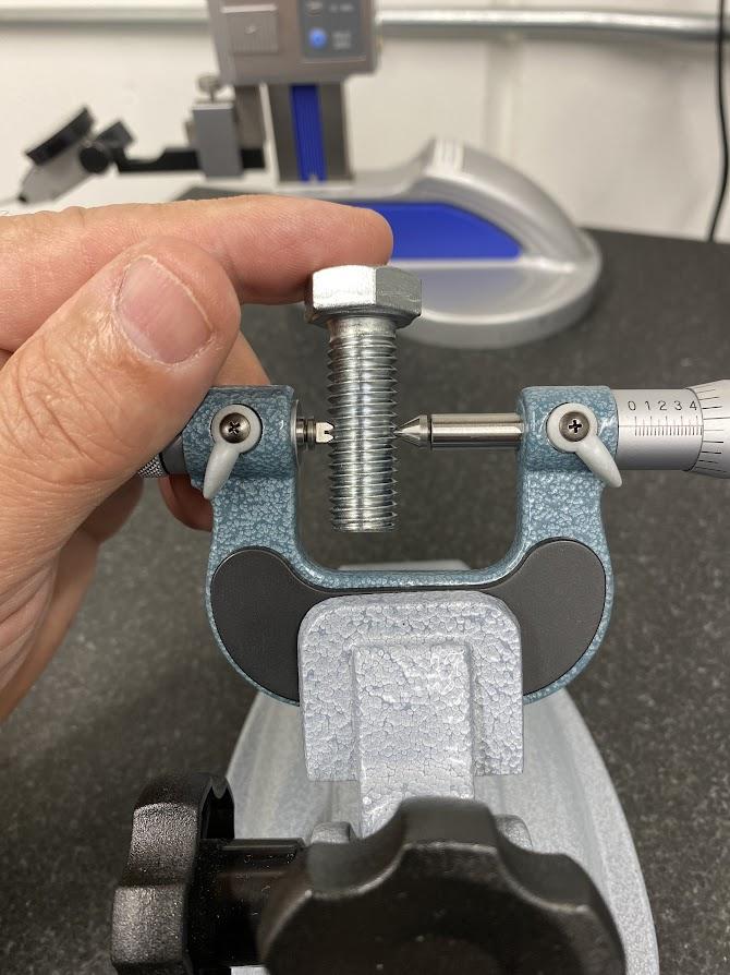
Gently close the micrometer over the thread to be measured.
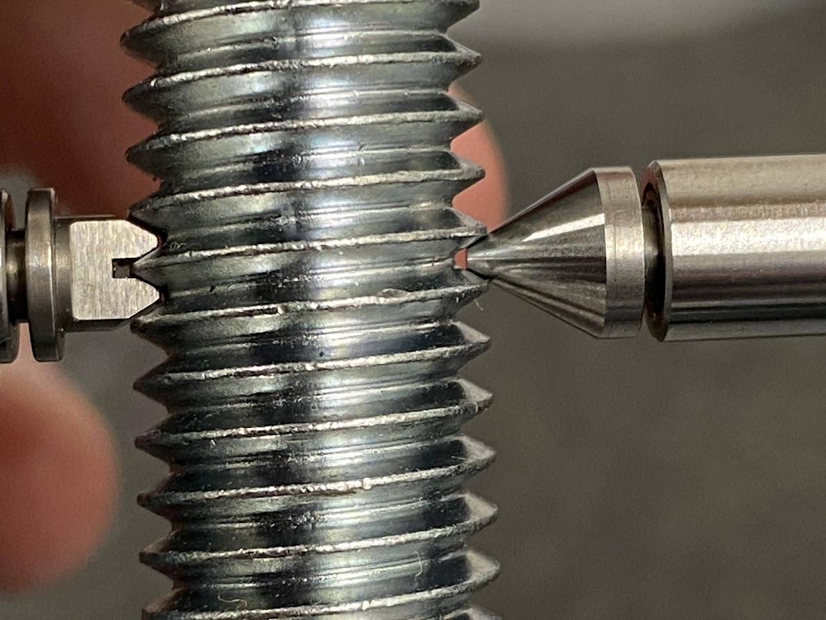
Finally, because of the cylindrical nature of a bolt, you will need to rock the bolt back and forth feeling for the peak of the measurement while adjusting the anvil until you detect the faintest rub against the anvils.
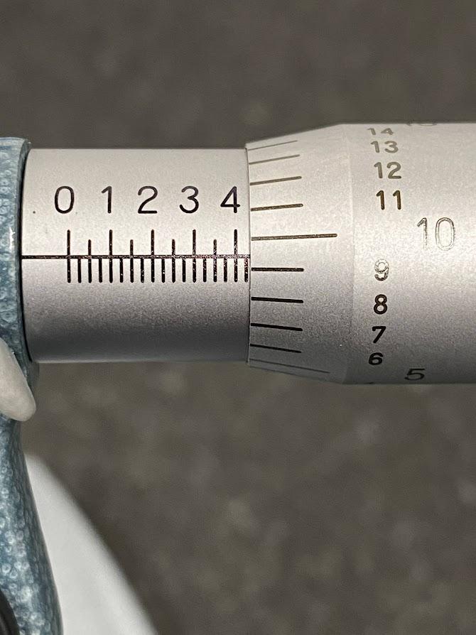
You are now ready to read the thread pitch diameter. This measurement is read as you would read a measurement on any ordinary OD vernier micrometer. Starting on the barrel, we can see the .400″ is exposed. Next record the .025″ value from the barrels. For our final thousandth position we see the 9 on the thimble is the closest value to the horizontal line on the barrel so we may add that to the .025 for a value of .034. Our thread pitch diameter for the 1⁄2-13 UNC thread is .434″. This micrometer does not have the .0001 ” position so we may estimate that with our eyecrometer, and call it .0005″ if necessary.
| External | ||||||||
| Nominal Size, Threads per Inch, and Series Designationa | Class | Allow-
ance |
Major Diameter
Maxd |
Major Diameter
Min |
Major Diameter
Mine |
Pitch Diameter
Maxd |
Pitch Diameter
Min |
UNR Minor Dia.,c Max (Ref.) |
|---|---|---|---|---|---|---|---|---|
| ½–12 UNS | 2A | 0.0016 | 0.4984 | 0.4870 | — | 0.4443 | 0.4389 | 0.3992 |
| ½–12 UNS | 3A | 0.0000 | 0.5000 | 0.4886 | — | 0.4459 | 0.4419 | 0.4008 |
| ½–13 UNC | 1A | 0.0015 | 0.4985 | 0.4822 | — | 0.4485 | 0.4411 | 0.4069 |
| ½–13 UNC | 2A | 0.0015 | 0.4985 | 0.4876 | 0.4822 | 0.4485 | 0.4435 | 0.4069 |
| ½–13 UNC | 3A | 0.0000 | 0.5000 | 0.4891 | — | 0.4500 | 0.4463 | 0.4084 |
Note. The Machinery’s Handbook (Jones et al., 2004) states the pitch diameter for a ½-13 UNC 2A thread is .4435 to .4485″ (p. 1740).
Inside Micrometers
Inside micrometers are used in applications where accurate measurements of internal dimensions are essential. Common uses include measuring the internal diameter of holes, cylinders, and bores in machine parts, engine components, bearings, and other objects. Inside micrometers provide precise and repeatable measurements, ensuring that components fit correctly and meet specified tolerances. They are valuable tools for quality control, manufacturing, and engineering tasks where precision is critical.
Depth Micrometers

Figure 4.73. A depth mic set in a box with a mic body and an assortment of different length anvils. / Image Credit: Damon Donner, CC BY 4.0
Depth micrometers are specifically designed to measure depth. Their size permits measuring areas where larger devices can not fit, such as in a CNC mill or lathe. A set like the one shown in Figure 4.73 is common in that it contains the mic body, a selection of anvils in varying lengths, and a small spanner for adjusting the barrel when calibration is needed.
It is important to notice the direction of scale graduations on a depth mic. When zeroed on a flat surface, the thimble is extended. As the thimble is turned in, the numbers increase. This is the opposite of standard micrometers and may take a couple of tries to understand.
The first step in measuring with a depth micrometer is to verify the zero. Place the micrometer on a flat surface, such as a surface plate (this unfinished surface in the photo is not optimum), and turn the thimble down until it gently contacts the flat surface. Notice the zero is off by about .0005″. Before adjusting the barrel with the spanner to set a good zero, try this again on a surface plate.
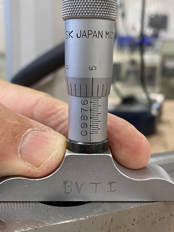
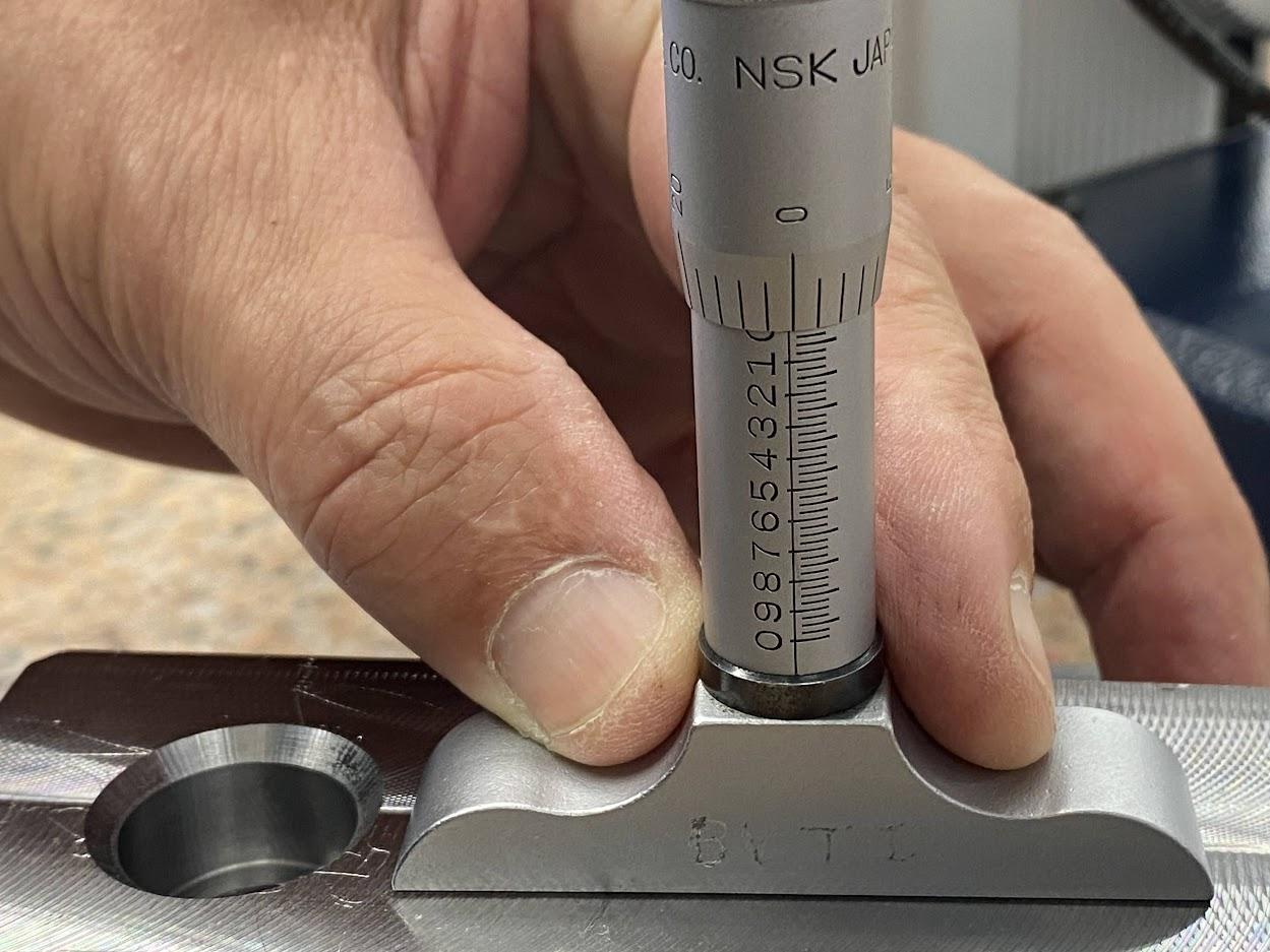
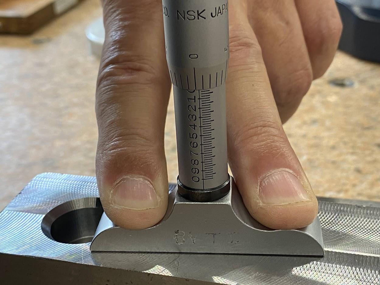
Place the micrometer spindle over the depth to be measured and turn the thimble down until the anvil gently contacts the surface. Read the feature depth on the micrometer scale using techniques from a standard micrometer vernier scale. Remember that the gradations on the depth micrometer increase in value with advancing turns.
The scale above indicates the counterbore depth at .530″. The thimble has covered the .525″ markings but NOT the .550 markings. Record the .525 from the barrel and then add the .005″ from the thimble. If this micrometer has .0001″ indications, we will add .004″ and then read the tenth’s scale to the last digit.
Attributions
- Figure 4.10: Parts of a slide caliper front by Damon Donner, for WA Open ProfTech, © SBCTC, CC BY 4.0
- Figure 4.11: Parts of a slide caliper back by Damon Donner, for WA Open ProfTech, © SBCTC, CC BY 4.0
- Figure 4.12: Outside dimension measurement by Damon Donner, for WA Open ProfTech, © SBCTC, CC BY 4.0
- Figure 4.13: Carbide jaw faces by Damon Donner, for WA Open ProfTech, © SBCTC, CC BY 4.0
- Figure 4.14: Inside dimension measurement by Damon Donner, for WA Open ProfTech, © SBCTC, CC BY 4.0
- Figure 4.15: Depth measurement dimension by Damon Donner, for WA Open ProfTech, © SBCTC, CC BY 4.0
- Figure 4.16: Depth measurement dimension by Damon Donner, for WA Open ProfTech, © SBCTC, CC BY 4.0
- Figure 4.17: Step dimension measurement by Damon Donner, for WA Open ProfTech, © SBCTC, CC BY 4.0
- Figure 4.18: A caliper is held against a 1-2-3 block by Damon Donner, for WA Open ProfTech, © SBCTC, CC BY 4.0
- Figure 4.19: Cleaning the caliper using a slip of paper by Damon Donner, for WA Open ProfTech, © SBCTC, CC BY 4.0
- Figure 4.20: Dial indicating zero before use by Damon Donner, for WA Open ProfTech, © SBCTC, CC BY 4.0
- Figure 4.21: Digital caliper closed to verify zero by Damon Donner, for WA Open ProfTech, © SBCTC, CC BY 4.0
- Figure 4.22: Digital caliper INC reading by Damon Donner, for WA Open ProfTech, © SBCTC, CC BY 4.0
- Figure 4.23: Cleaning the slide caliper movement by Damon Donner, for WA Open ProfTech, © SBCTC, CC BY 4.0
- Figure 4.24: Measuring OD by closing the jaws by Damon Donner, for WA Open ProfTech, © SBCTC, CC BY 4.0
- Figure 4.25: Measuring OD by pushing the sliding jaw by Damon Donner, for WA Open ProfTech, © SBCTC, CC BY 4.0
- Figure 4.26: Measuring the OD by using the slide wheel by Damon Donner, for WA Open ProfTech, © SBCTC, CC BY 4.0
- Figure 4.27: Using the thumb wheel to set 1.000″ by Damon Donner, for WA Open ProfTech, © SBCTC, CC BY 4.0
- Figure 4.28: Measuring a short shelf by Damon Donner, for WA Open ProfTech, © SBCTC, CC BY 4.0
- Figure 4.29: Measuring the larger of the two dimensions by Damon Donner, for WA Open ProfTech, © SBCTC, CC BY 4.0
- Figure 4.30: Measure the larger dimension by Damon Donner, for WA Open ProfTech, © SBCTC, CC BY 4.0
- Figure 4.31: The caliper placed on the shorter shelf by Damon Donner, for WA Open ProfTech, © SBCTC, CC BY 4.0
- Figure 4.32: Measuring the depth of a blind hole by Damon Donner, for WA Open ProfTech, © SBCTC, CC BY 4.0
- Figure 4.33: Close the caliper over the pin. Ensure a tight fit by Damon Donner, for WA Open ProfTech, © SBCTC, CC BY 4.0
- Figure 4.34: Pressing the INC button establishes an incremental zero by Damon Donner, for WA Open ProfTech, © SBCTC, CC BY 4.0
- Figure 4.35: Use the height measure feature of the caliper to measure the pin length by Damon Donner, for WA Open ProfTech, © SBCTC, CC BY 4.0
- Figure 4.36: A clearer view of the caliper in contact with the surface by Damon Donner, for WA Open ProfTech, © SBCTC, CC BY 4.0
- Figure 4.37: The reading on the display by Damon Donner, for WA Open ProfTech, © SBCTC, CC BY 4.0
- Figure 4.38: OD micrometers by Damon Donner, for WA Open ProfTech, © SBCTC, CC BY 4.0
- Figure 4.39: 0-1″ OD digital micrometer by Damon Donner, for WA Open ProfTech, © SBCTC, CC BY 4.0
- Figure 4.40: Components of a micrometer by Damon Donner, for WA Open ProfTech, © SBCTC, CC BY 4.0
- Figure 4.41: Spindle and anvil faced With carbide by Damon Donner, for WA Open ProfTech, © SBCTC, CC BY 4.0
- Figure 4.42: Low battery indicator by Damon Donner, for WA Open ProfTech, © SBCTC, CC BY 4.0
- Figure 4.43: Metrology calibration sticker by Damon Donner, for WA Open ProfTech, © SBCTC, CC BY 4.0
- Figure 4.44: Cleaning the anvil and spindle faces by Damon Donner, for WA Open ProfTech, © SBCTC, CC BY 4.0
- Figure 4.45: Verify zero before use by Damon Donner, for WA Open ProfTech, © SBCTC, CC BY 4.0
- Figure 4.46: Verify the vernier scale reads zero by Damon Donner, for WA Open ProfTech, © SBCTC, CC BY 4.0
- Figure 4.47: Incremental zero set by Damon Donner, for WA Open ProfTech, © SBCTC, CC BY 4.0
- Figure 4.48: 1-2″ micrometer and a 1″ standard by Damon Donner, for WA Open ProfTech, © SBCTC, CC BY 4.0
- Figure 4.49: Measuring with a micrometer by Damon Donner, for WA Open ProfTech, © SBCTC, CC BY 4.0
- Figure 4.50: Holding a micrometer by Damon Donner, for WA Open ProfTech, © SBCTC, CC BY 4.0
- Figure 4.51: Anvil contacting the part by Damon Donner, for WA Open ProfTech, © SBCTC, CC BY 4.0
- Figure 4.52: Spindle face contacting the part by Damon Donner, for WA Open ProfTech, © SBCTC, CC BY 4.0
- Figure 4.53: Turn the thimble a few turns by Damon Donner, for WA Open ProfTech, © SBCTC, CC BY 4.0
- Figure 4.54: Micrometer stand by Damon Donner, for WA Open ProfTech, © SBCTC, CC BY 4.0
- Figure 4.55: Micrometer clamped in a mic stand by Damon Donner, for WA Open ProfTech, © SBCTC, CC BY 4.0
- Figure 4.56: Reading the thousandths of an inch graduations by Damon Donner, for WA Open ProfTech, © SBCTC, CC BY 4.0
- Figure 4.57: Reading a micrometer to .0001” by Nicholas Malara, for WA Open ProfTech, © SBCTC, CC BY 4.0
- Figure 4.58: Reading a micrometer to 0.01mm by Nicholas Malara, for WA Open ProfTech, © SBCTC, CC BY 4.0
- Figure 4.59: Reading a micrometer to 0.001mm by Nicholas Malara, for WA Open ProfTech, © SBCTC, CC BY 4.0
- Figure 4.60: A blade micrometer used to measure a groove depth by Damon Donner, for WA Open ProfTech, © SBCTC, CC BY 4.0
- Figure 4.61: Blade micrometer in a mic stand by Damon Donner, for WA Open ProfTech, © SBCTC, CC BY 4.0
- Figure 4.62: Disc micrometer by Damon Donner, for WA Open ProfTech, © SBCTC, CC BY 4.0
- Figure 4.63: Disc micrometer measuring a stud by Nicholas Malara, for WA Open ProfTech, © SBCTC, CC BY 4.0
- Figure 4.64: 0-1″ Thread micrometer with anvil selection by Damon Donner, for WA Open ProfTech, © SBCTC, CC BY 4.0
- Figure 4.65: V- and conical anvils for a thread micrometer by Damon Donner, for WA Open ProfTech, © SBCTC, CC BY 4.0
- Figure 4.66: Thread micrometer anvil selection by Damon Donner, for WA Open ProfTech, © SBCTC, CC BY 4.0
- Figure 4.67: Thread mic empty jaws by Damon Donner, for WA Open ProfTech, © SBCTC, CC BY 4.0
- Figure 4.68: Thread mic zero set by Damon Donner, for WA Open ProfTech, © SBCTC, CC BY 4.0
- Figure 4.69: Thread mic 13 TPI by Damon Donner, for WA Open ProfTech, © SBCTC, CC BY 4.0
- Figure 4.70: Thread mic closed by Damon Donner, for WA Open ProfTech, © SBCTC, CC BY 4.0
- Figure 4.71: Close the spindle on to the thread by Damon Donner, for WA Open ProfTech, © SBCTC, CC BY 4.0
- Figure 4.72: Reading the scale on a thread micrometer by Damon Donner, for WA Open ProfTech, © SBCTC, CC BY 4.0
- Figure 4.73: Representation of a depth micrometer by Damon Donner, for WA Open ProfTech, © SBCTC, CC BY 4.0
- Figure 4.74: Vernier scale on a depth mic by Damon Donner, for WA Open ProfTech, © SBCTC, CC BY 4.0
- Figure 4.75: Zero the depth micrometer by Damon Donner, for WA Open ProfTech, © SBCTC, CC BY 4.0
- Figure 4.76: Measuring a counterbore depth with a micrometer by Damon Donner, for WA Open ProfTech, © SBCTC, CC BY 4.0
a measurement performed on the outside of a part.
a measurement performed on an inside feature of a part.
a gage that measures small distances
is a piece of equipment with a calibrated size that is used to check other pieces of inspection equipment.
A cutting operation that uses a single point cutting tool (boring bar) to produce an internal conical, or cylindrical feature by enlarging an existing opening in a workpiece.
