4.6 Snap gages
D.M. Donner
Snap gages are relatively inexpensive tools which are used to measure the ID of parts. They are transfer devices which require the use of a micrometer to determine the final dimension.
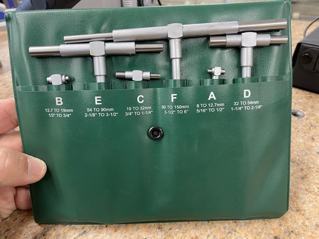
Snap gages come in sets to measure various bore sizes. A bore is a cylindrical feature created to enlarge a drilled hole. Snaps gages are used to record the diameter of a hole and then transfer that recording to a direct reading tool such as an OD micrometer.
Snap gages have two collapsible anvils, which can be locked in place by rotating a knob on the end of the handle.
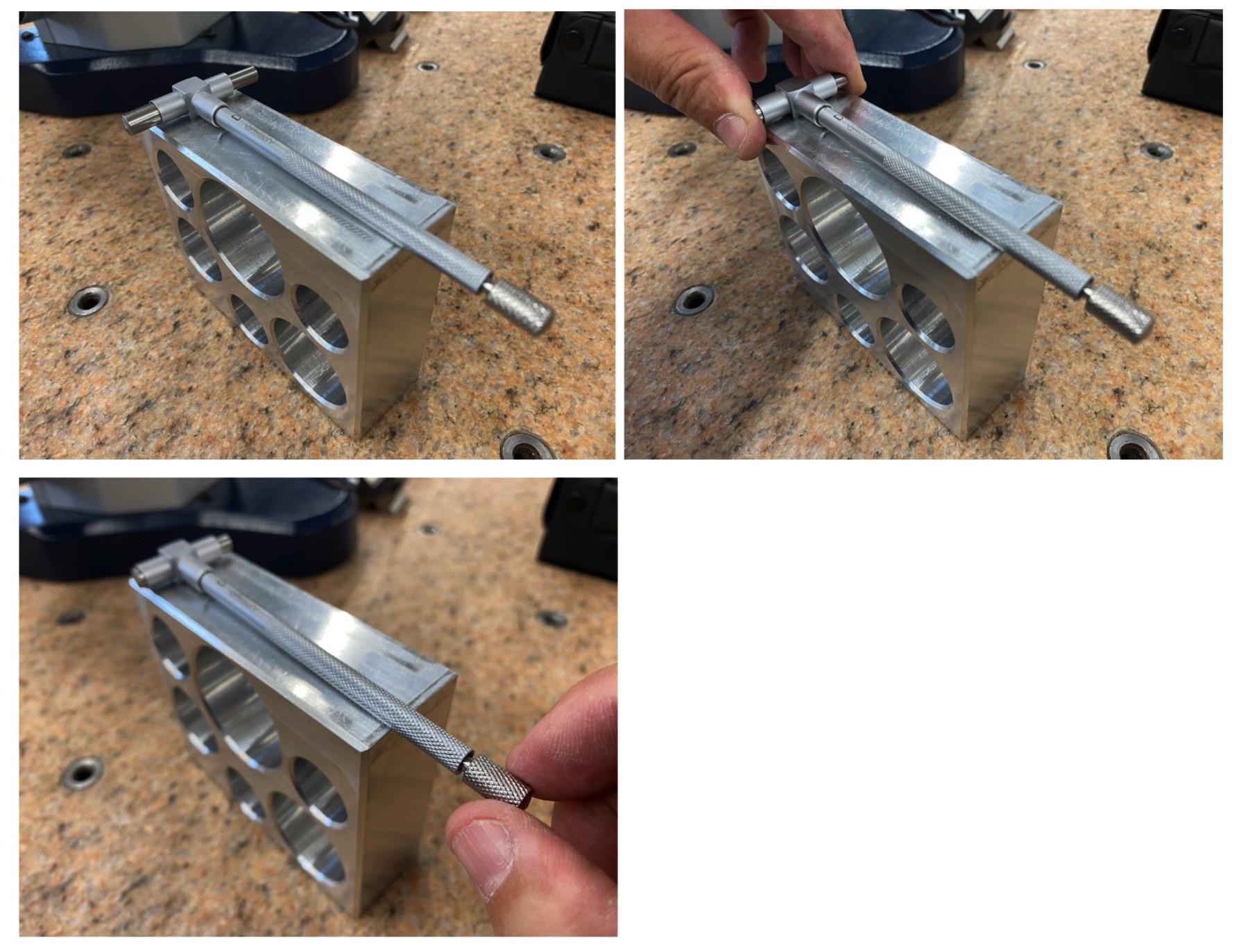
To measure a bore, a snap gage is set with the anvils extended to a diameter larger than the bore. Then, the following steps are taken.
1. Collapse the anvils and place in the bore at an angle as pictured above.
2. Turn the lock. This applies pressure to the anvils, restricting their movement.
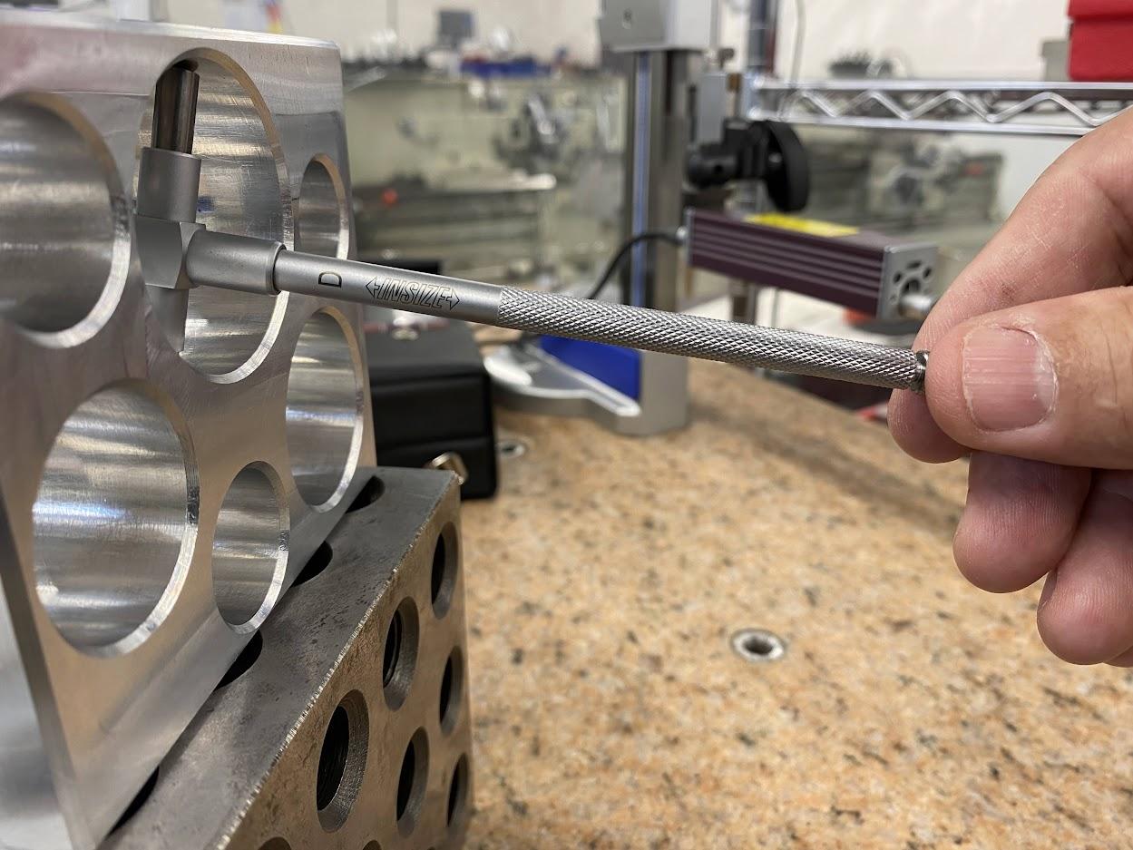
3.Swing the snap gage so that the arms compress as they pass through the bore diameter.
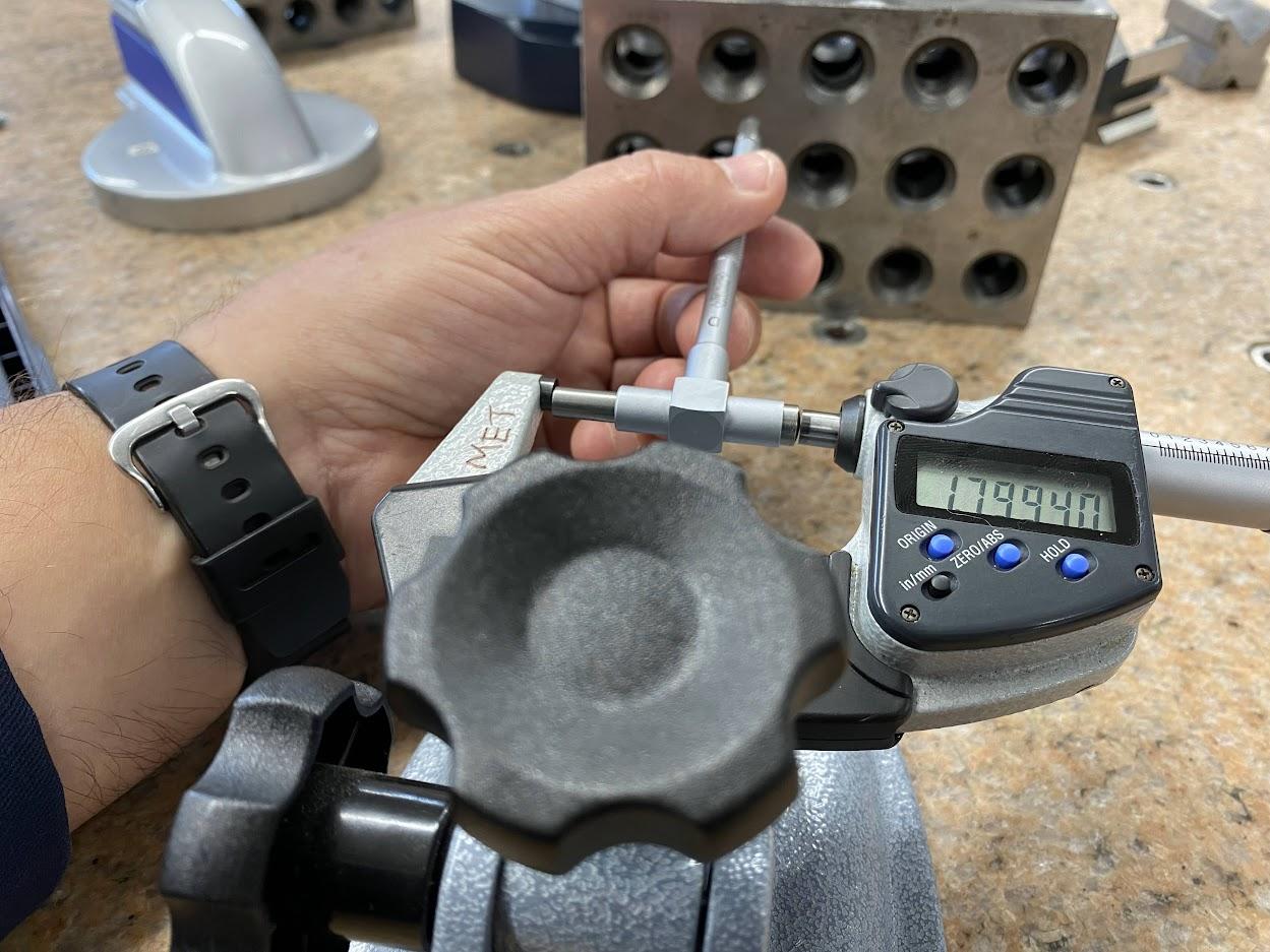
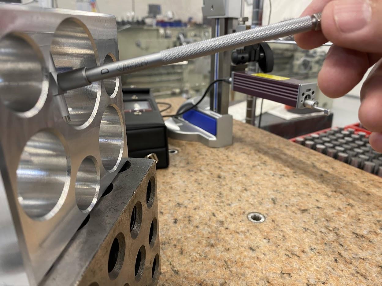
4.Take the snap gage to a micrometer and gently measure the length created by the anvils.
Attributions
- Figure 4.96: Snap gages used to measure bores by Damon Donner, for WA Open ProfTech, © SBCTC, CC BY 4.0
- Figure 4.97: Snap gage anvils and lock by Damon Donner, for WA Open ProfTech, © SBCTC, CC BY 4.0
- Figure 4.98: Install snap gage by Damon Donner, for WA Open ProfTech, © SBCTC, CC BY 4.0
- Figure 4.99: Swing snap gage by Damon Donner, for WA Open ProfTech, © SBCTC, CC BY 4.0
- Figure 4.100: Read the diameter on a micrometer by Damon Donner, for WA Open ProfTech, © SBCTC, CC BY 4.0
