5.8 Files
D.M. Donner
Files were invented to remove material during the manufacturing process. They are some of the first tools designed to perform this task, and the history of this tool is vast (McGeough & Hartenberg, 2023). Technology has almost eliminated hand files from the manufacturing process with the evolution of more sophisticated cutting tools. However, when performing benchwork, we do not use complicated tooling, so the file finds a nice home here.
Files take a back seat to saws when it comes to material removal, but a saw can not remove material very close to a layout line. This is when we reach for a file. Files are tools made from hardened steel with small cutting edges designed to remove material in small slivers called filings.
As with all machining processes, there are roughing and finishing operations. Filing is no different. There are rough cutting files with aggressive teeth designed to remove as much material as possible per stroke. And, there are files with smaller cutting edges to achieve an accurate and smooth cut.
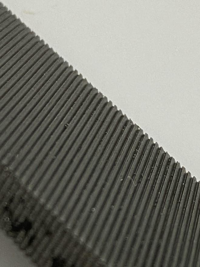
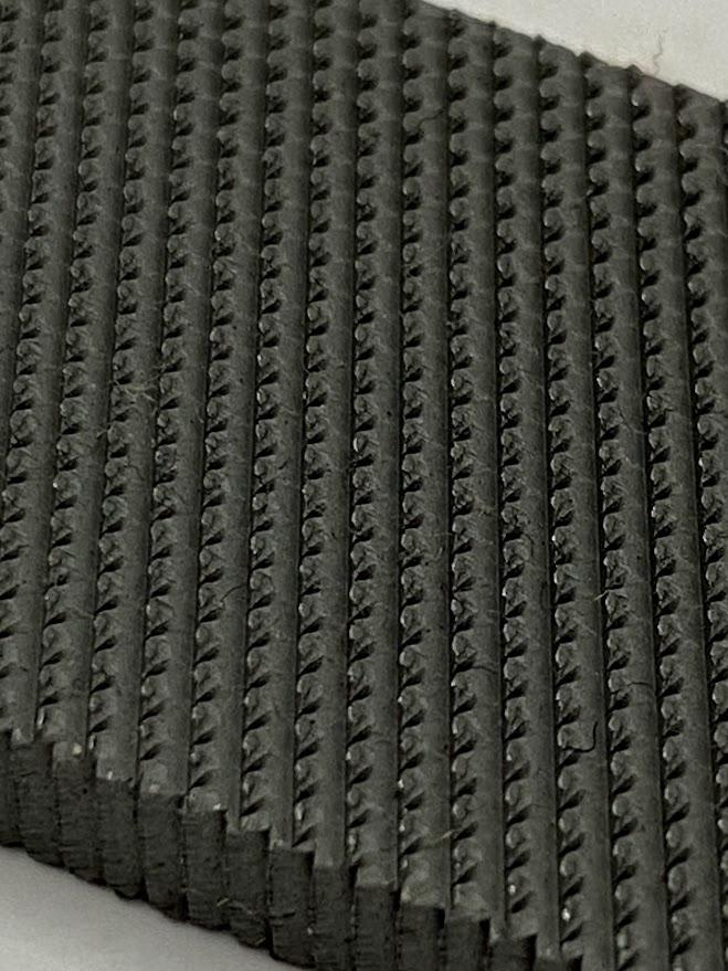
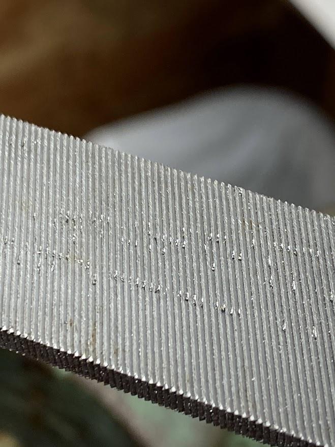
A simplified explanation of files categorizes them for roughing and finishing processes. The roughing type files are double cut files, meaning the cutting edges are created by a crisscross pattern on the face of the file. This design creates a more aggressive pattern intended for maximum material removal and not for a smooth finish. A single cut file has a single row of cutting teeth much like a saw blade and they remove material in a less aggressive manner than the double cut files.
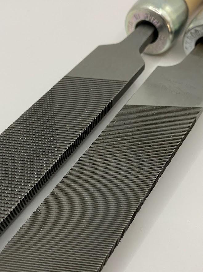
In the photo above the double cut edges on the left file are obvious next to a single cut file on the right. Having both of these files on hand is necessary for both aggressive material removal used in roughing actions and finer controlled material removal used in finishing actions. The term “bastard” refers to the grade of cut. It is the most aggressive after smooth and second/medium cut grades. For general benchwork activities, bastard cut files work best, and they are the most popular cuts available.

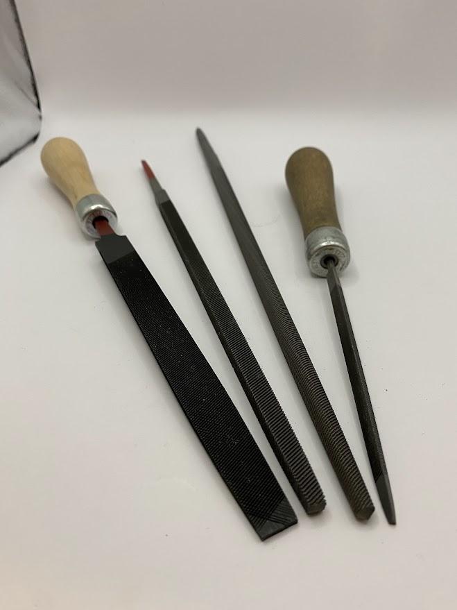
Files are one of the most versatile tools for cutting metal. This is due to their selection of cuts, shapes, and sizes. In the figure above, a small selection of files represents some of the shapes available. The flats on the left are common in 6-12″ lengths in both single and double cut. The square file is nice for cutting features with square corners. The round file can cut radius features into parts. Finally, the triangle file is essential due to the 60° angle that can be used to repair external threads.
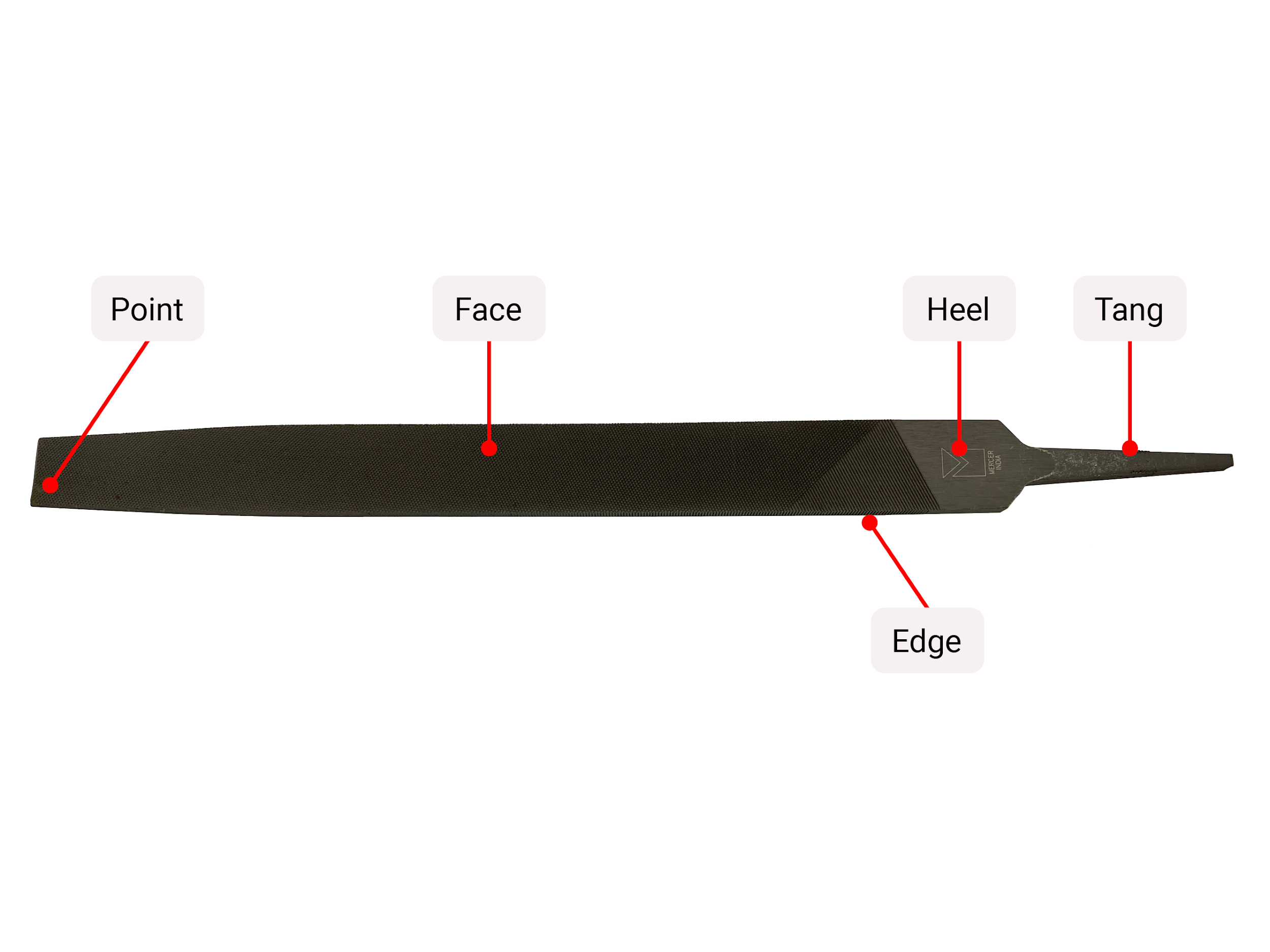
The figure above lists the parts of a file. The point is the far end, opposite the heel. The tang is an annealed portion of the file used to attach a handle. Annealing is a process used on hardened parts where the material is softened, in this case by allowing a handle to be threaded onto the tang. The cutting features are located on the face and edge of the file. One exception are lathe files which have safe edges that do not cut.
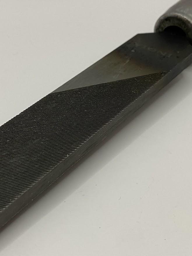
The figure above is an example of a lathe file with safe edges. The safe edge lacks cutting teeth and prevents damaging adjacent surfaces while filing. The lathe file also has longer and steeper cut edges, which is useful for finishing actions such as draw filing.
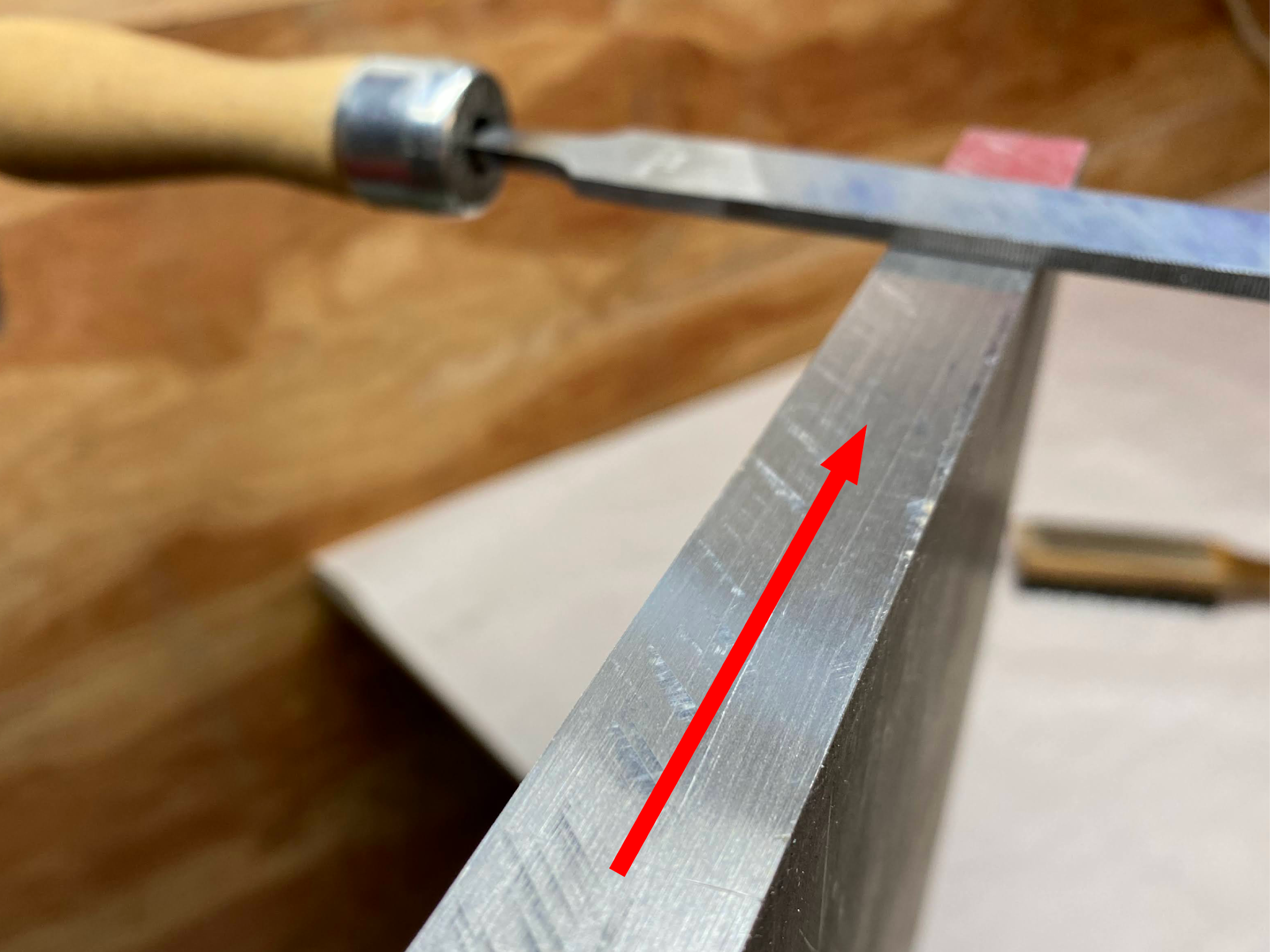
Draw filing is a fine finishing technique where the file is perpendicular to the surface being filed and the file is either pushed or pulled depending on which direction the cutting edges are facing. In the figure above, the handle is on the left, so the draw file is performed by pushing away. This provides an effective shearing motion, creating a very fine surface.
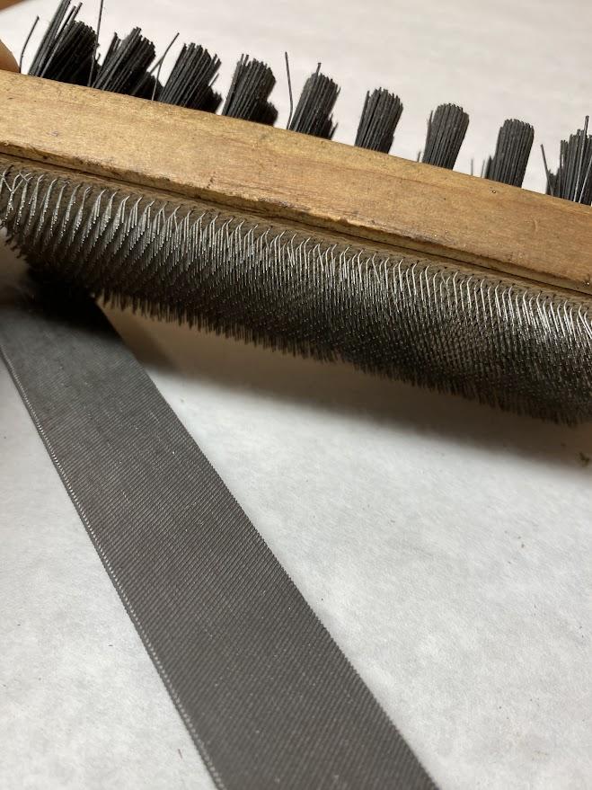
A file card is a brush designed to clean the cutting edges on files by brushing away filings. One side of the brush has nylon bristles for most uses, and the backside has metal teeth similar to those used in the carding process of processing cotton into threads.
The spaces between teeth on a file, similar to hacksaw blades, fill with filings and can reduce the effectiveness of the file or damage the surface of the part. For this reason, clean the file often using the file card. To best manage filings, use both sides of the file, rotating from one side to the other when the teeth get full, and brushing the filings from the teeth as you go. Using this technique will aid in faster filings and reduce the chance of pinning the filings into the teeth. Pinning refers to a situation where filings accumulate and weld themselves into the space between file teeth. Pinning requires the use of a pick to pry the material loose.
The cutting edges on a file extend from the heel to the point. Use the full length of the file when possible, making long strokes. The cutting edges on a file are oriented toward the point meaning the teeth only cut on the forward stroke of the file. Excessive pressure applied during the return stroke may damage the teeth.
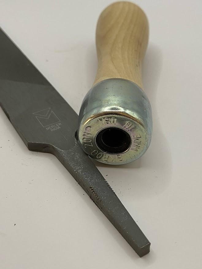
The tang on a file is the part designed for attaching a handle. Failing to use a handle on a file can cause personal injury. Remember, the file is made of hardened tool steel. The tang has been softened through annealing to allow the handle to thread onto the tang (figure above). The handle has been added to enhance comfort, control, and protection of the user.
Attributions
- Figure 5.51: Selection of hand files by Damon Donner, for WA Open ProfTech, © SBCTC, CC BY 4.0
- Figure 5.52: Double cut bastard file by Damon Donner, for WA Open ProfTech, © SBCTC, CC BY 4.0
- Figure 5.53: Single cut bastard file by Damon Donner, for WA Open ProfTech, © SBCTC, CC BY 4.0
- Figure 5.54: Double and single cut bastard files by Damon Donner, for WA Open ProfTech, © SBCTC, CC BY 4.0
- Figure 5.55: Shapes of files by Damon Donner, for WA Open ProfTech, © SBCTC, CC BY 4.0
- Figure 5.56: Parts of a file by Damon Donner, for WA Open ProfTech, © SBCTC, CC BY 4.0
- Figure 5.57: Lathe file with safe edges by Damon Donner, for WA Open ProfTech, © SBCTC, CC BY 4.0
- Figure 5.58: Draw filing by Damon Donner, for WA Open ProfTech, © SBCTC, CC BY 4.0
- Figure 5.59: A file card by Damon Donner, for WA Open ProfTech, © SBCTC, CC BY 4.0
- Figure 5.60: Cutting edges on a single cut file by Damon Donner, for WA Open ProfTech, © SBCTC, CC BY 4.0
- Figure 5.61: Tang and handle by Damon Donner, for WA Open ProfTech, © SBCTC, CC BY 4.0
tools made from hardened steel with small cutting edges designed to remove material in small slivers called filings.
Please look for related terms in the Glossary
has a single row of cutting teeth much like a saw blade and they remove material in a less aggressive manner than the double cut files.
a process used on hardened parts where the material is softened
A file with sides that lack cutting teeth and prevents damaging adjacent surfaces while filing.
a brush designed to clean the cutting edges on files by brushing away filings.
a file is the part designed for attaching a handle
