6.2 Technical Drawings
Tim A. Bacon
A picture is Worth a Thousand Words
Since this chapter describes job planning to make a bench block, let’s explore the technical drawing for the bench block.
Understanding technical drawings, covered in Chapter 3, is essential for a machinist to ensure that the final machined part meets the designed specifications, dimensional accuracy, material requirements, and functional expectations of the customer. A technical drawing is considered a contract between the customer and the machinist. It should clearly state what the customer requires so that the machinist knows what is expected and acceptable.
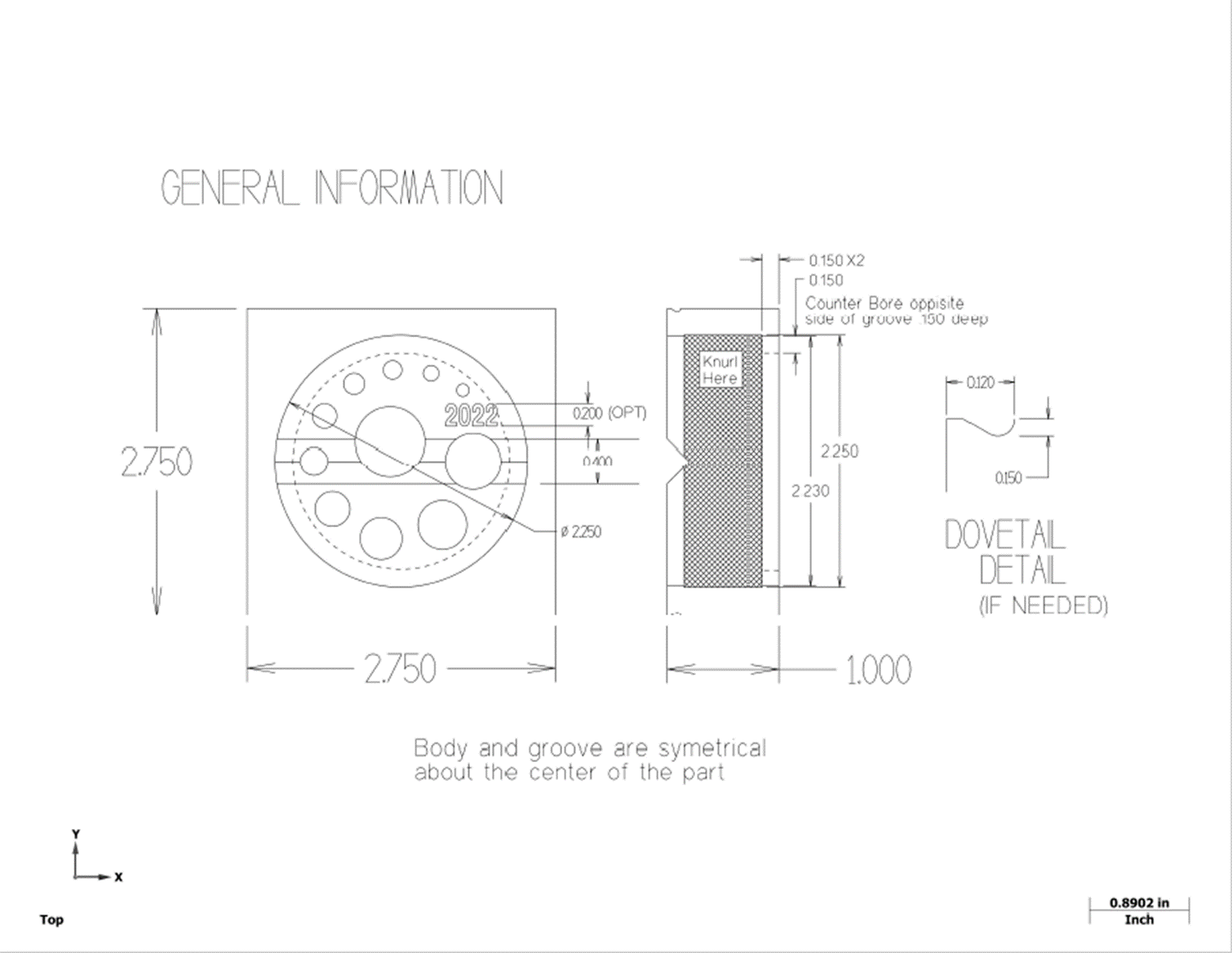
When you first look at this drawing, note that it starts out as a square part that measures 2.75 inches by 2.75 inches by 1.0 inch. The finished part will retain most of the 1.0-inch thickness, but it will have a diameter of 2.25 +/-.002. Also, note that a series of holes will need to be established, along with a V groove down the middle. Finally, there is a recessed pocket on the bottom and knurling on the side of the part.
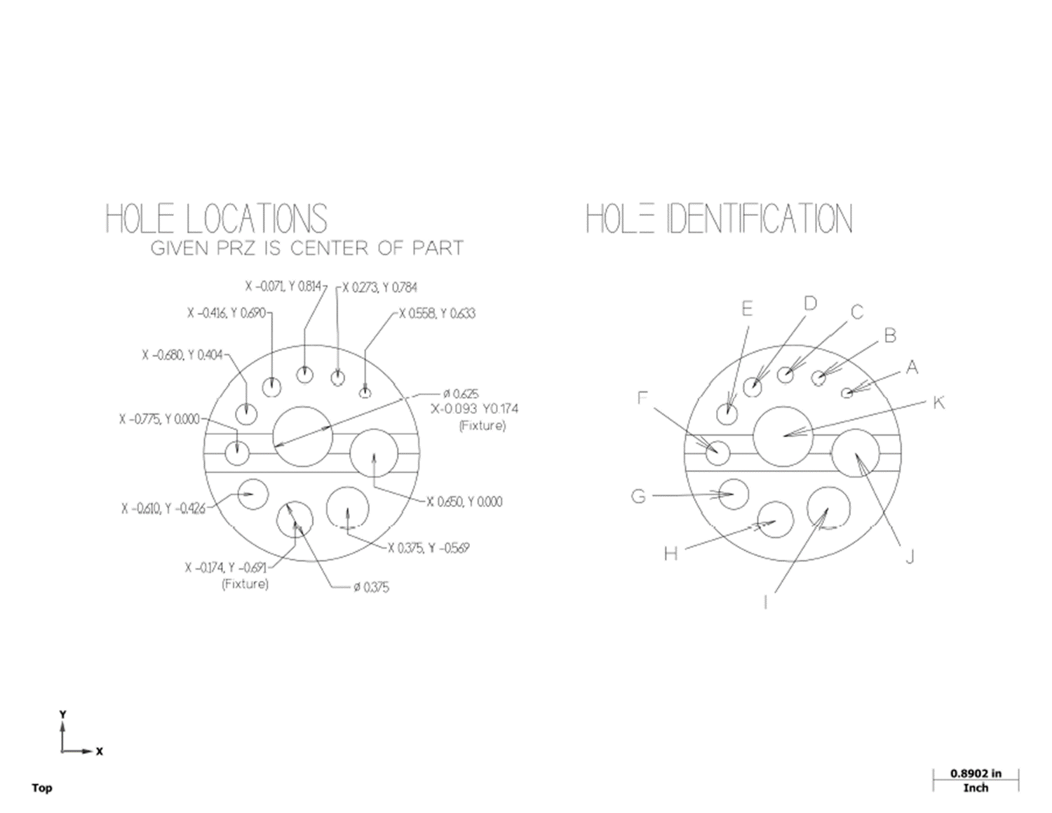
The second drawing shows the hole locations on the part. As you lay out your job plan, it is important to note the steps for making holes. Once we find the center of the part, the tool that will cut the hole can be moved to the coordinate shown. Then, the hole will be spot drilled so that the next drill doesn’t walk off the precise point where you need it. After these initial steps are done, the drilling starts. Ensure each hole is completely through the part before continuing. The last stage, when needed, is to bore the hole. This opens up the holes while maintaining a quality finish.
When a machinist receives an order for a part, several papers and information will be provided. This can be considered the job packet, or work order. The data sheet provides the specific information needed for creating the holes in the part. When making the holes, the machinist would only have to refer to this page.
| Hole | Position | Position | Drill | Decimal | N/A | Guide for |
|---|---|---|---|---|---|---|
| N/A | X | Y | Thru | Size | Notes | Tap size |
| A | 0.558 | 0.633 | #32 | 0.116 | CB .140 to .6 deep | 4-40 |
| B | 0.273 | 0.784 | #28 | 0.140 | N/A | 6-32 |
| C | -0.071 | 0.814 | #19 | 0.166 | N/A | 8-32 |
| D | -0.416 | 0.690 | #9 | 0.196 | N/A | 10-24 |
| E | -0.680 | 0.404 | 7/32 | 0.218 | N/A | 12-24 |
| F | -0.775 | 0.000 | 6.5mm | 0.256 | N/A | 1/4-20 |
| G | -0.610 | -0.426 | P | 0.323 | N/A | 5/16-18 |
| H | -0.174 | -0.691 | 3/8 | 0.375 | Bore to .380 | 3/8-16 |
| I | 0.375 | -0.569 | 7/16 | 0.438 | Bore to .446 | 7/16-14 |
| J | 0.650 | 0.000 | 1/2 | 0.500 | Bore to .508 | 1/2-13 |
| K | -0.093 | 0.174 | 5.8 | 0.625 | Bore to .634 | 5/8-11 |
Note: The table shows the hole identified by letter, the location based off of the center of the part on the X and Y axis; the name of the drill with a decimal equivalent, notes for special directions, and the size of tap that will fit into the hole for aligning perpendicularly to a part.
The holes are identified by letter in the first column of the table. The next two columns give the location of the hole. The drill name and decimal equivalent for the hole size are listed next. The notes column is used to indicate that some of the holes need to be made bigger. The last column is a note showing what the hole will be used for, i.e., a ½-13 tap will slide through hole J.
The work order for the bench block will include several papers. A technical drawing has general information and dimensions. A detailed drawing shows the coordinates of each hole based off of the center of the part. A data table is included to show the hole locations, sizes, and any special notes. Looking at the data table, the notes indicate that some of the holes will have to be opened up with a boring operation.
Recall from Chapter 3 that technical drawings are of the utmost importance in the field of machining. These drawings serve as a primary means of communication between designers, engineers, and machinists. They provide precise instructions, and specifications for making the products, and will help determine the job plan. Machining involves shaping raw materials into intricate parts and components. Any inaccuracies, or misinterpretations can lead to costly errors, and delays in production. By comprehending the technical drawings, machinists can accurately interpret dimensions, tolerances, feature relationships, and material requirements. This will ensure that the final product meets the customer’s specifications.
Often, there is not a right or wrong choice in determining the sequence of events in a project plan. Yet, some decisions may result in more work, while others are more efficient. For example, by cutting the outside of a part first, the machinist may be required to make special tooling to hold the part to finish the rest of the part. This approach may be more or less efficient than another approach.
The quantity of parts to be made can also affect the plan. If only one part is being made, a reliable process will take precedence over efficiency. If a significant number of parts are ordered, efficiency will be foremost during the planning stage. Finally, the decisions made when determining the job plan should also take into consideration the accuracy required and the lead time.
Other factors to consider are when the customer needs the parts, and whether a secondary operation will be required? Secondary operations include activities such as applying paint or plating. Heat treating can also be performed to help improve the material’s characteristics, such as strength or durability. In the grand scheme of the project, the job plan is made from the best information available.
Attributions
- Figure 6.3: Bench block general information by T Bacon, courtesy of Bates Technical College, for WA Open ProfTech, © SBCTC, CC BY 4.0
- Figure 6.4: Bench block hole locations by T Bacon, courtesy of Bates Technical College, for WA Open ProfTech, © SBCTC, CC BY 4.0
The process of impressing revolving grooved wheels into the surface of a part. The material is displaced to create a pattern of straight, or diamond-shaped raised ridges on a metal workpiece.
