8.3 Machine Components
Micky R. Jennings
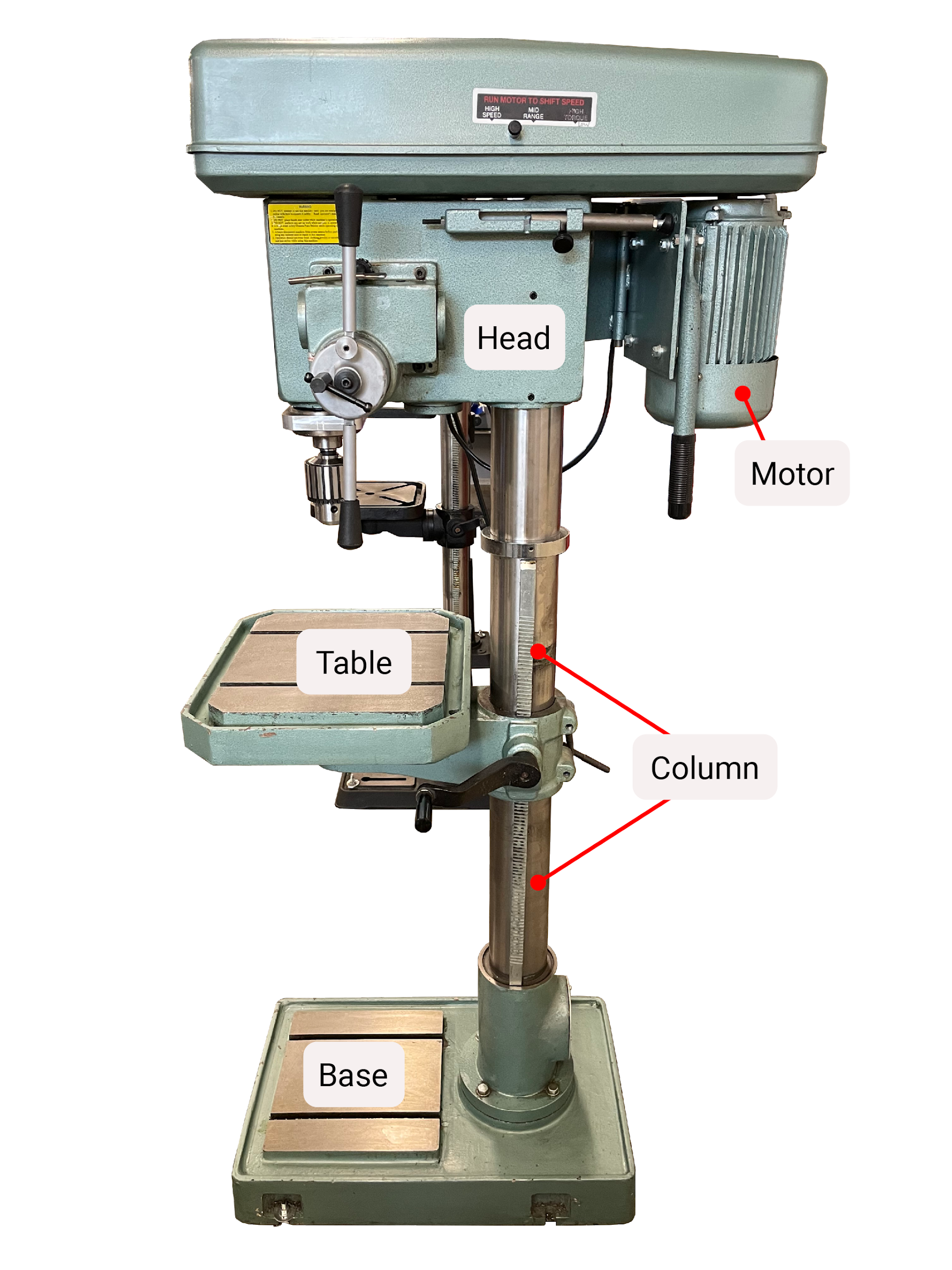
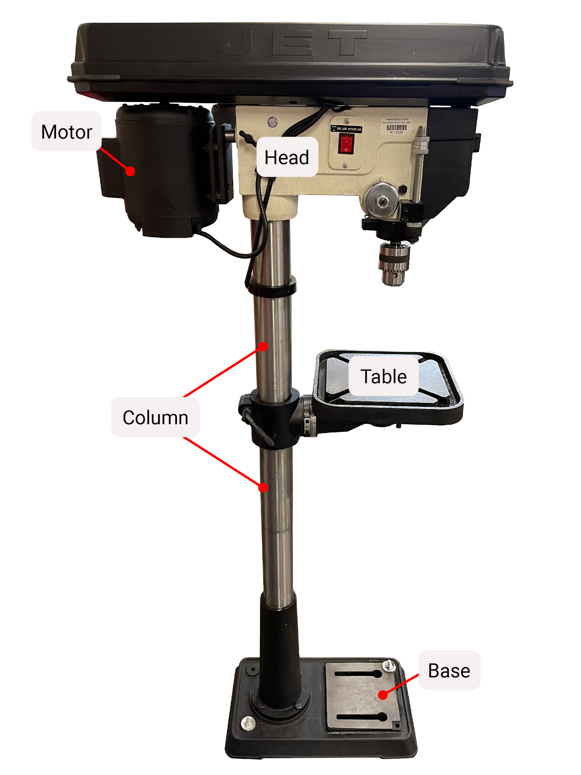
It is important that all drill press operators are familiar with the components of the machinery they are using. Getting to know the equipment, features, and functionality will help the machinist perform work in the safest and most efficient manner, as well as give them the industry specific nomenclature necessary to effectively communicate with coworkers.
Base
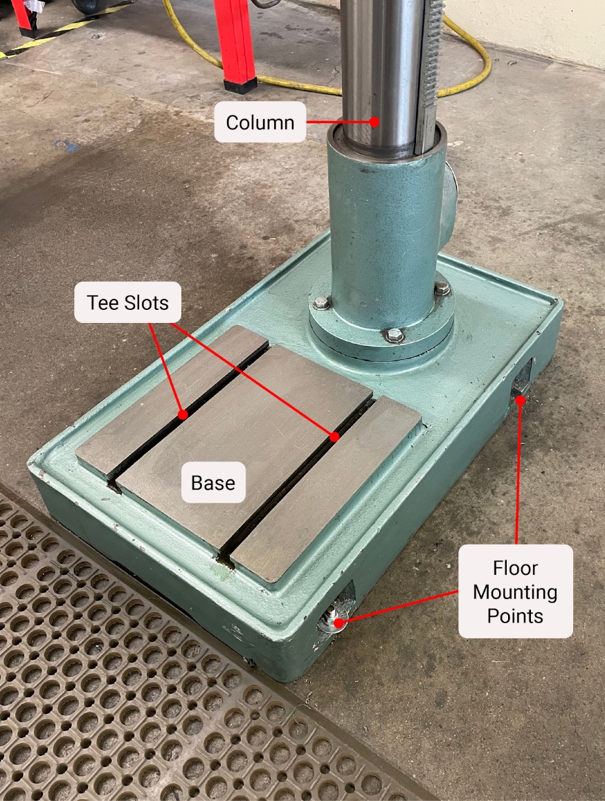
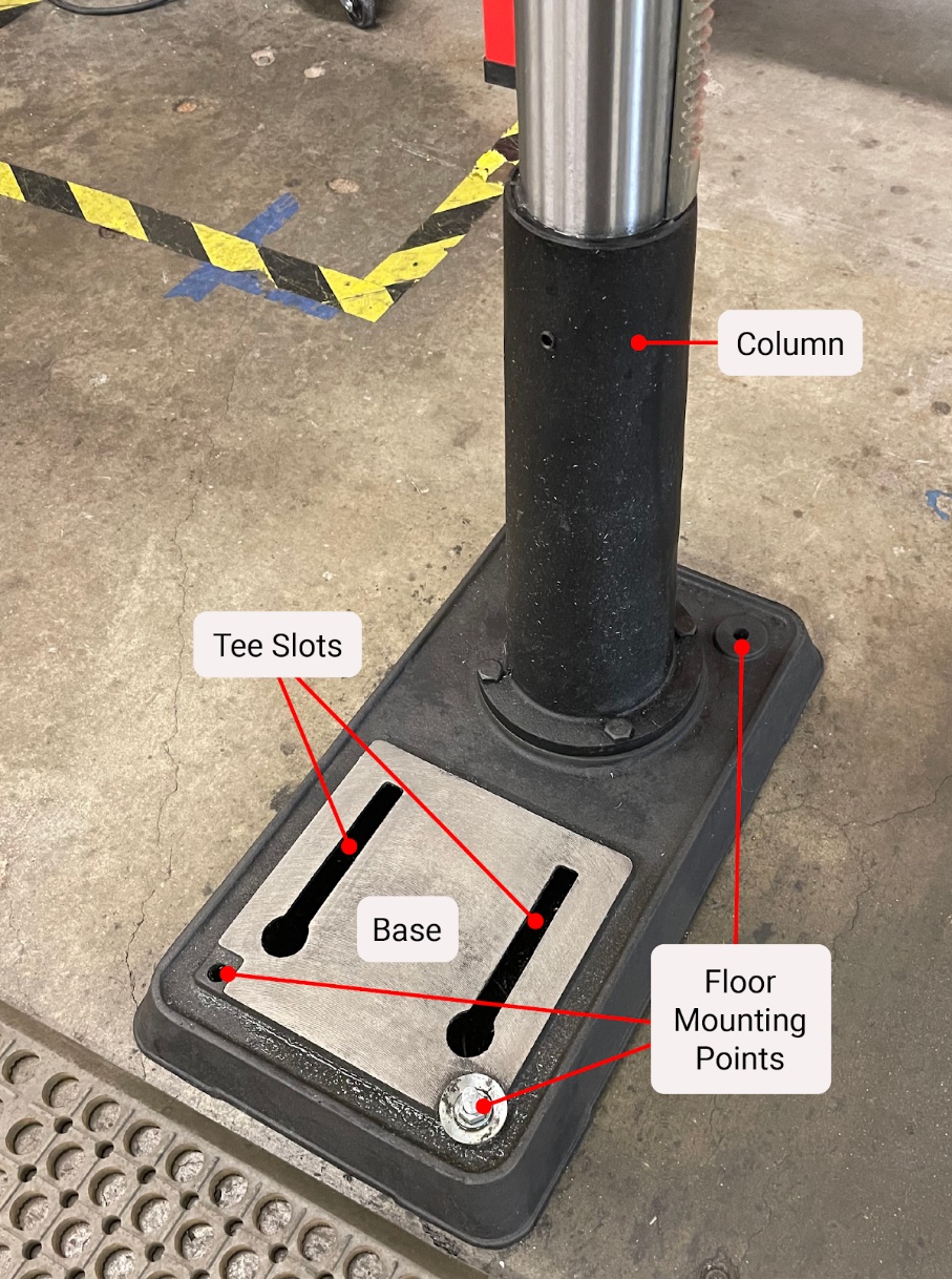
The base of the machine is the supporting feature, typically made of heavy cast iron. It is often bolted to the floor for maximum stability. The base includes a flat surface used to bolt large parts by way of the integrated tee slots. The back of the base is where the column is attached.
Column
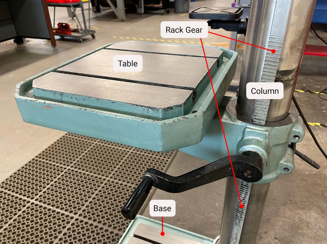
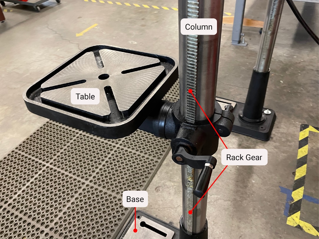
The column is a precision cylindrical shaped rigid tube that is attached to the base. The column provides support for the other components, tying them to the base. The head of the drill press is located at the top of the column, while the table travels between the base and head.
Table
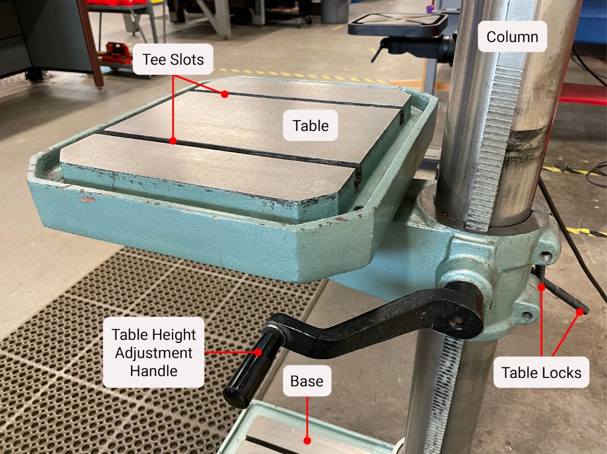
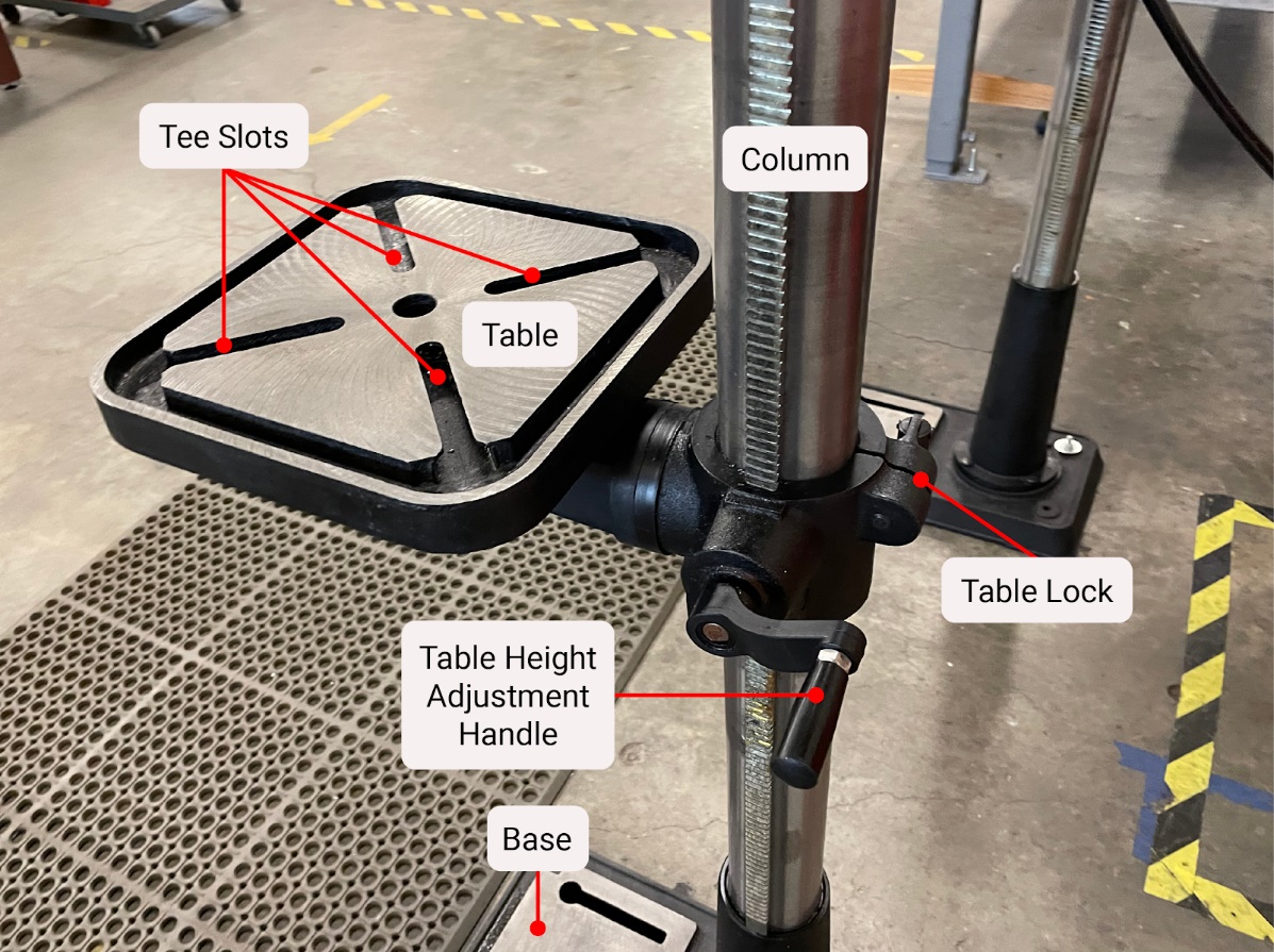
The table of the drill press is designed to support the work. The operator positions the table along the column and locks it in place. It is adjustable up and down, rotates side to side, and may rotate or twist to suit different hole making operations. The up and down movement sometimes employs a mechanism for ease of adjustment.
Head
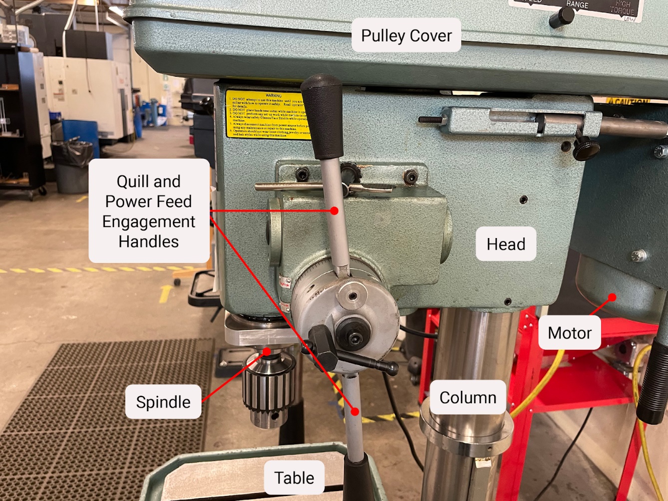
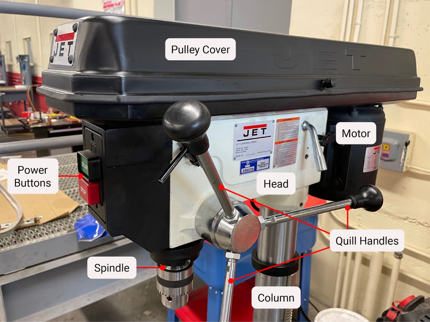
The head is attached at the top of the column and contains the electrical components, on/off switches, gearing, pulleys, quill, and spindle. On the right side of the head is a handle for moving the quill up and down to create movement for the hole-making operations. The motor is mounted at the back of the head.
Motor
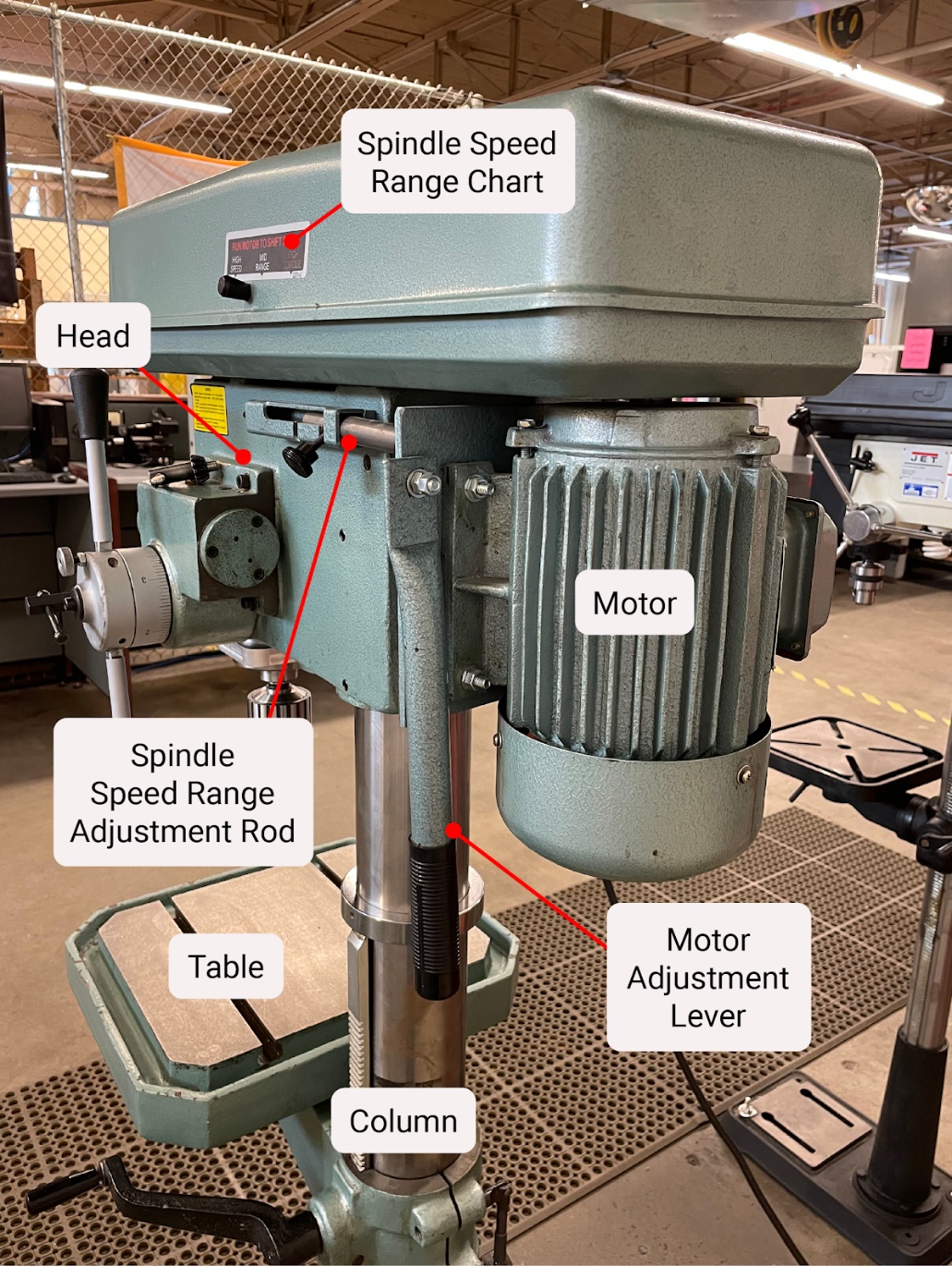

The motor is the power source for the drill press, and it is attached to the drill press head. Motors come in various horsepower ratings, depending on the size of the drill press and the intended work performed. During operation, the motor turns a series of belts and pulleys to rotate the spindle.
Pulleys
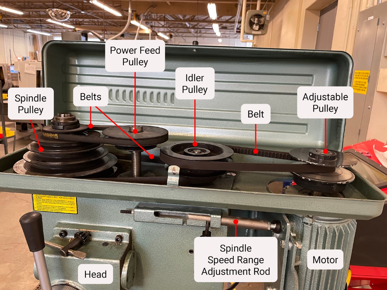
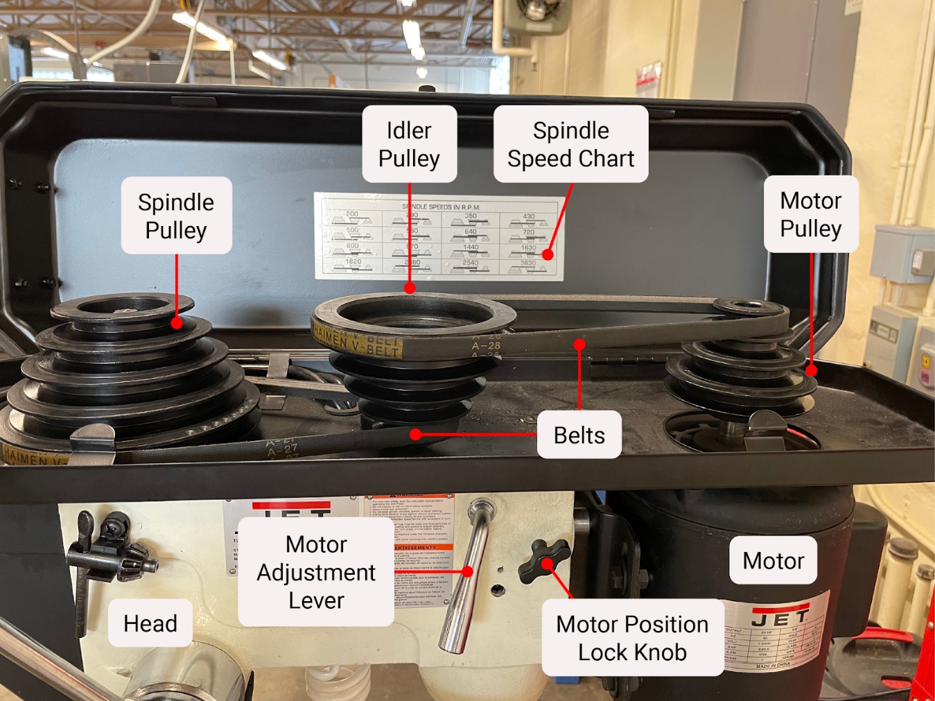
The pulleys of the drill press are utilized to transmit rotational movement from the motor to the spindle by way of vee belts. The belts can often be moved to different pulley steps in order to select spindle speeds. Some drill presses may use an adjustable pulley to select spindle speed ranges, while finer adjustments are made with a variable frequency drive.
Spindle
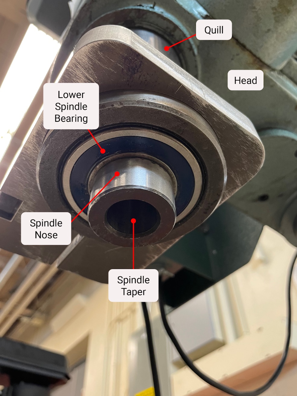

The spindle is located within the drill press head and holds the tooling by way of a Morse taper. The spindle rotates on bearings inside the quill and provides the rotational movement necessary to perform the machining operations. It is connected to the motor by a series of belts and pulleys.
Quill
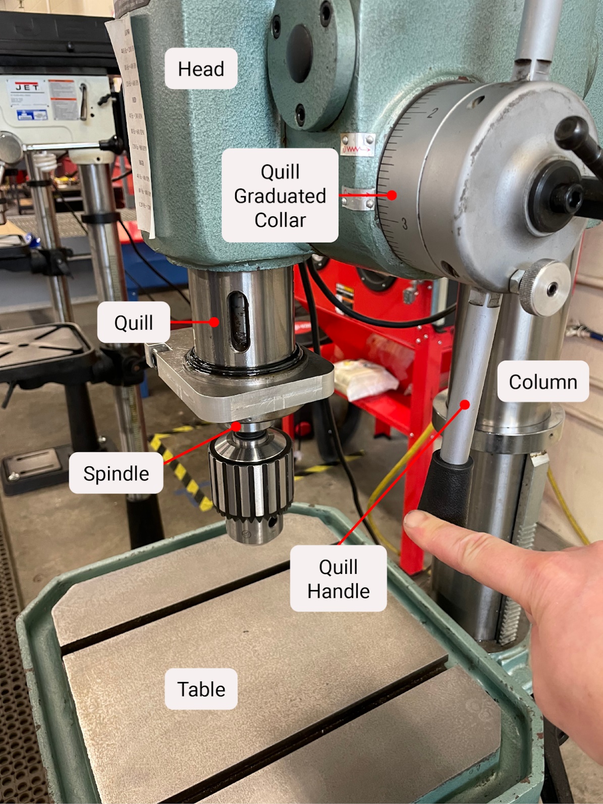
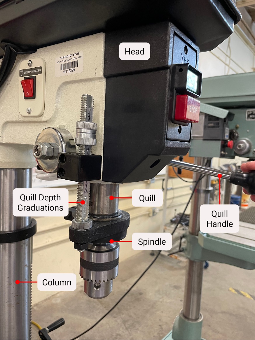
The quill is a cylindrical component that rides up and down in the head when the machine’s quill handle is pulled. The quill handle of the drill press is attached to a spur gear and meshes with a rack machined into the back of the quill. The spindle is located inside the quill and rotates on bearings.
Quill Stop
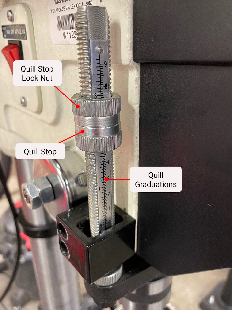
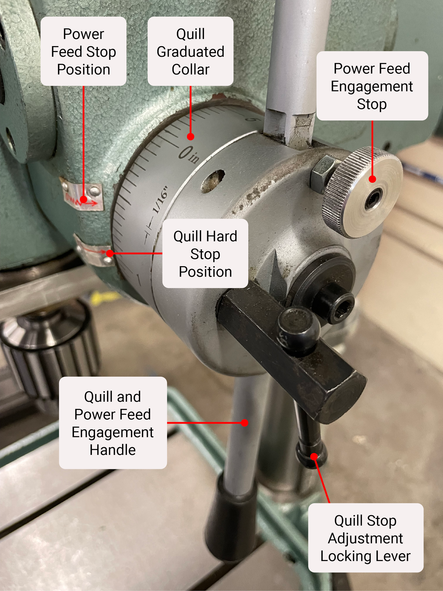
The quill stop is a device that allows the operator to limit the downward movement of the quill. By limiting the quill’s movement, the operator can accurately adjust and set the depth of features. This is especially handy for machining the same feature in multiple locations. Quill stops come in a few different styles. One uses a simple threaded rod with nuts that can be positioned to limit movement. Another type uses a more complex mechanism that is incorporated into the quill handle.
Author’s Tip
I prefer the threaded rod style because of its ease of use and the systematic way it can be adjusted. All I need to know is the pitch of the threaded rod and I can easily adjust the stop nuts in very fine increments by rotating them fractions of a turn. I often find the more complex mechanisms difficult to adjust in small increments, as they often just rely on rotating a graduated collar with respect to a pointing device. The graduated collar is often in course increments like 1/16″ and not very useful for precise depth cuts.
Attributions
- Figure 8.7: Variable speed drill press with parts labeled by Micky R. Jennings, courtesy of Wenatchee Valley College, for WA Open ProfTech, © SBCTC, CC BY 4.0
- Figure 8.8: Sensitive drill press with parts labeled by Micky R. Jennings, courtesy of Wenatchee Valley College, for WA Open ProfTech, © SBCTC, CC BY 4.0
- Figure 8.9: Drill press base by Micky R. Jennings, courtesy of Wenatchee Valley College, for WA Open ProfTech, © SBCTC, CC BY 4.0
- Figure 8.10: Drill press base 2 by Micky R. Jennings, courtesy of Wenatchee Valley College, for WA Open ProfTech, © SBCTC, CC BY 4.0
- Figure 8.11: Drill press column by Micky R. Jennings, courtesy of Wenatchee Valley College, for WA Open ProfTech, © SBCTC, CC BY 4.0
- Figure 8.12: Drill press column 2 by Micky R. Jennings, courtesy of Wenatchee Valley College, for WA Open ProfTech, © SBCTC, CC BY 4.0
- Figure 8.13: Drill press table by Micky R. Jennings, courtesy of Wenatchee Valley College, for WA Open ProfTech, © SBCTC, CC BY 4.0
- Figure 8.14: Drill press table 2 by Micky R. Jennings, courtesy of Wenatchee Valley College, for WA Open ProfTech, © SBCTC, CC BY 4.0
- Figure 8.15: Drill press head by Micky R. Jennings, courtesy of Wenatchee Valley College, for WA Open ProfTech, © SBCTC, CC BY 4.0
- Figure 8.16: Drill press head 2 by Micky R. Jennings, courtesy of Wenatchee Valley College, for WA Open ProfTech, © SBCTC, CC BY 4.0
- Figure 8.17: Variable speed drill press motor by Micky R. Jennings, courtesy of Wenatchee Valley College, for WA Open ProfTech, © SBCTC, CC BY 4.0
- Figure 8.18: Single speed drill press motor by Micky R. Jennings, courtesy of Wenatchee Valley College, for WA Open ProfTech, © SBCTC, CC BY 4.0
- Figure 8.19: Pulleys by Micky R. Jennings, courtesy of Wenatchee Valley College, for WA Open ProfTech, © SBCTC, CC BY 4.0
- Figure 8.20: Pulleys 2 by Micky R. Jennings, courtesy of Wenatchee Valley College, for WA Open ProfTech, © SBCTC, CC BY 4.0
- Figure 8.21: Spindle inside quill by Micky R. Jennings, courtesy of Wenatchee Valley College, for WA Open ProfTech, © SBCTC, CC BY 4.0
- Video 8.1: Micky R. Jennings, courtesy of Wenatchee Valley College, for WA Open ProfTech, © SBCTC, CC BY 4.0
- Figure 8.22: Quill by Micky R. Jennings, courtesy of Wenatchee Valley College, for WA Open ProfTech, © SBCTC, CC BY 4.0
- Figure 8.23: Quill 2 by Micky R. Jennings, courtesy of Wenatchee Valley College, for WA Open ProfTech, © SBCTC, CC BY 4.0
- Figure 8.24: Quill stop by Micky R. Jennings, courtesy of Wenatchee Valley College, for WA Open ProfTech, © SBCTC, CC BY 4.0
- Figure 8.25: Quill stop 2 by Micky R. Jennings, courtesy of Wenatchee Valley College, for WA Open ProfTech, © SBCTC, CC BY 4.0
The bottom feature of a piece of machinery, often attached to the floor.
A vertical component of machinery that extends from the base to other components.
The component where material or a work holding device is placed, on a machine tool.
The component of a machine that contains the spindle.
The component of a machine that provides the power for machining operations.
A part of the powertrain that aids in transmitting power from the motor to the spindle.
The powered rotational component of a machine tool.
The telescoping component on machine tools that allows for easy hole making procedures.
A mechanism that allows for a maximum depth to be set for the quill movement.
