8.7 Tooling
Micky R. Jennings
Tooling is a term used to refer to the cutting and measuring equipment used to make parts in a machine shop. On a drill press, the primary tooling will be the cutting tools used for making holes as well as the tools used for alignment purposes. These same tools are used in other operations as well, and mastering the skills necessary to use them will allow the machinist to perform a variety of hole-making operations.
Center Finder (wiggler)
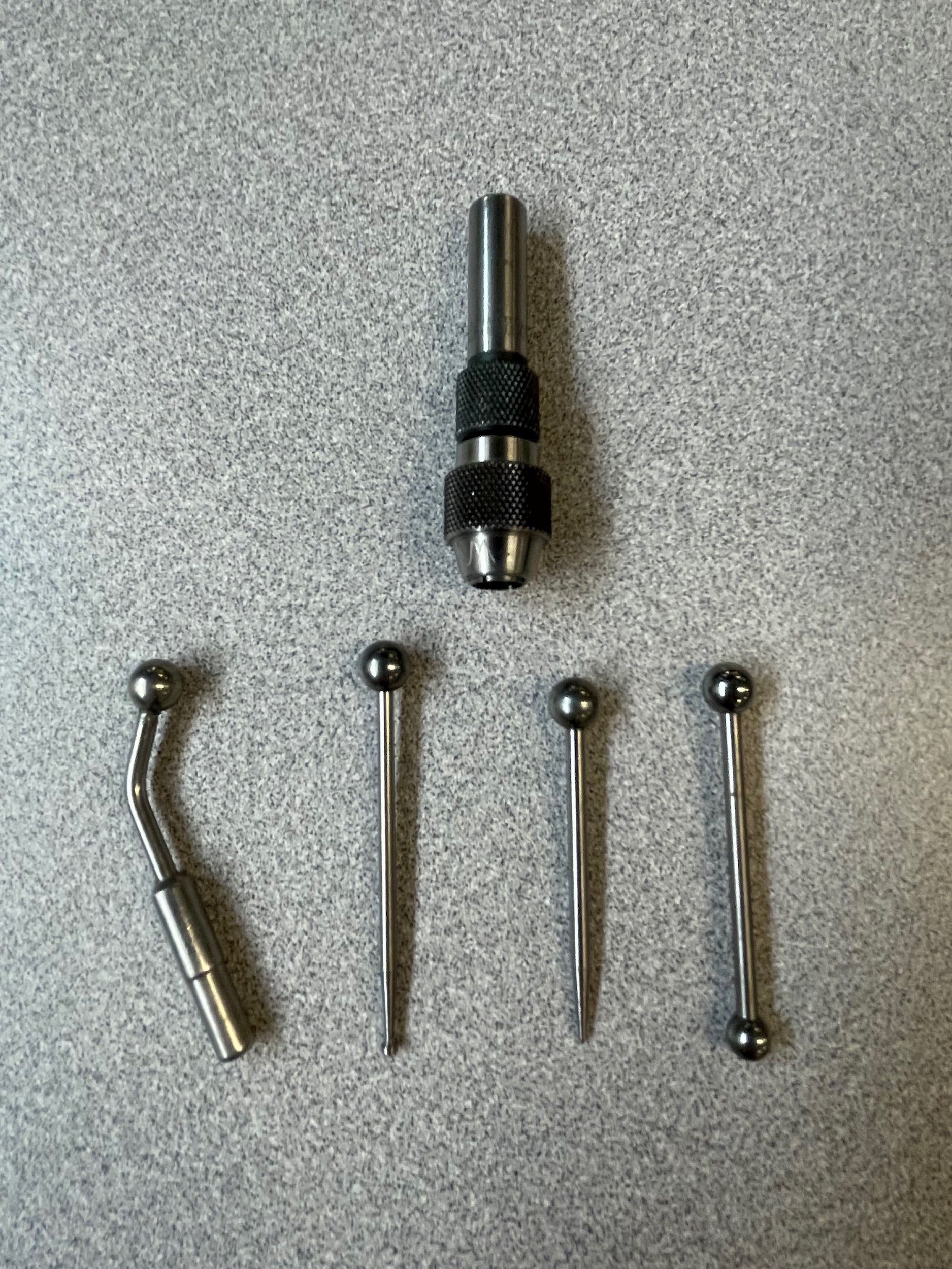
A center finder, also known as a wiggler, is a device used on a drill press or milling machine to aid in finding the position, or center, of features. The indicator attachment is used to sweep features in a rotational fashion, allowing the indicator to help with accuracy. The disk and ball attachments are used to help find the sides or edges of surfaces. The pointer attachment is used to show the absolute center of the spindle rotation, allowing the operator to visually adjust the work position. These attachments are helpful on a drill press because it can be difficult to line up the spindle in the correct position when the job requires the drill press vise to be clamped in one place.
Center Drill
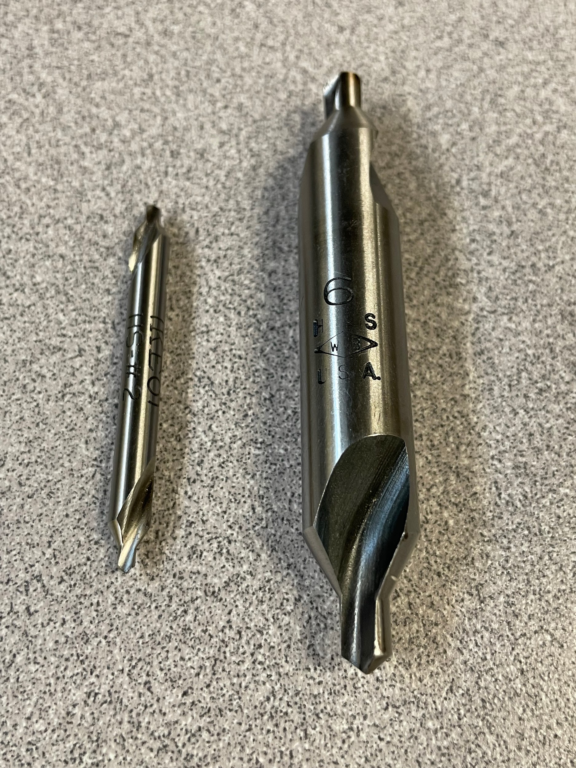
A center drill is designed to create a “center” for support of lathe work. However, because of their short, rigid construction and split point, they are often used to spot hole positions before drilling. Standard center drills consist of a small pilot drill diameter and a 60-degree [pb_glossary id=187]countersink[/pb_glossary]. The 60-degree countersink is what creates the feature lathes need for centering purposes. Center drills are identified by number size. Smaller numbers indicate smaller tools, while a larger number indicates a larger tool. For general purposes, #2 – #4 are common. A machining reference book will have charts that give specifics on the dimensions of the different center drill numbers. Some center drills may have a radius instead of a countersink. These are primarily used when cutting tapers on a lathe by way of the tailstock offset method, and will be discussed further in the lathe chapter.
Spot Drill
A spot drill is a short, rigid twist drill that is used to spot holes before using a twist drill. These drills are intended to cut just on the tip of the tool and do not have the relief or flute length required for through drilling.
Author’s Tip
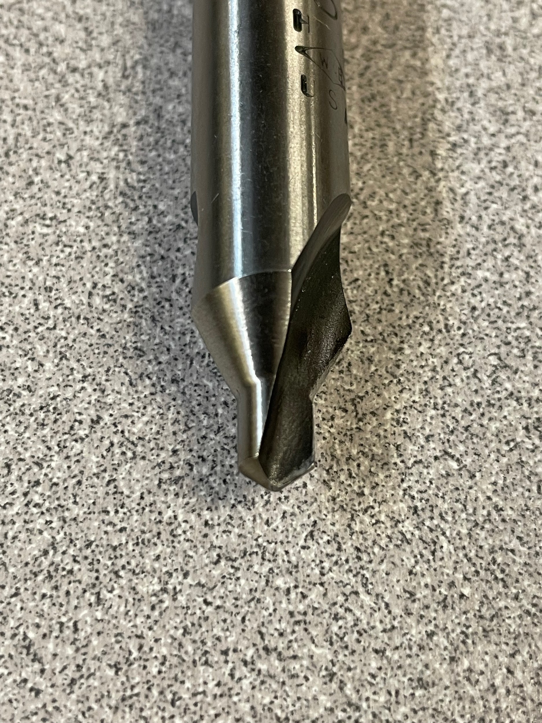
A basic spot drill can have a larger diameter than the pilot of a center drill, although center drills are often used in spotting holes. I use this to my advantage and add extra depth to my spotted holes, creating an edge break or chamfer at the top of the intended hole. This can be a huge time saver because it eliminates the need for a chamfer tool afterwards, as well as deburring the inside burrs the chamfer tool will leave. Using a 90-degree spot drill helps me calculate the spot depth necessary to create the correct diameter for the chamfer. A center drill can be used for this purpose instead, but often, the center drill needs to be large, and it can be difficult to acquire. A center drill also presents the added difficulty of calculating a 60-degree chamfer or edge break if that is needed.
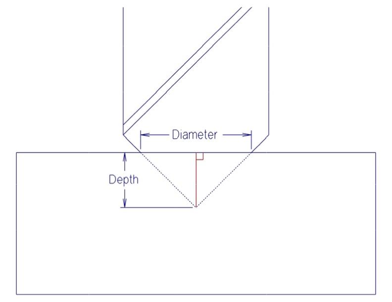
When calculating the depth of the 90-degree tool, we know that we have a 45-45-90 triangle situation. The depth of the spot is one leg of the triangle, and half the diameter is the other leg. These two legs are equal. Based on that, we can figure out the diameter of the hole by multiplying one leg by two. The formula I use whenever I am spotting holes is:
Drill depth = diameter required / 2
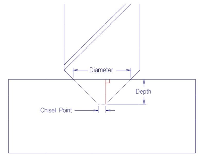
This formula works really well with sharp, pointed spot drills, but sometimes a spot drill may have a chisel point on the end that fouls up the math. In that instance, you have to take the chisel point flat into consideration. We know that as soon as the tool touches the work, we will have a diameter forming from the chisel point. For that reason, we need to subtract that diameter from the required diameter in order to figure out the correct drill depth. Ignoring the chisel point will result in a spot that is drilled too deep. The revised formula is:
Drill depth = (diameter required – chisel point) / 2
The math to calculate a chamfer with a spot drill and 60-degree countersink isn’t too much more difficult, but it does require adding some trigonometric calculations to the above formulas.
Twist Drill
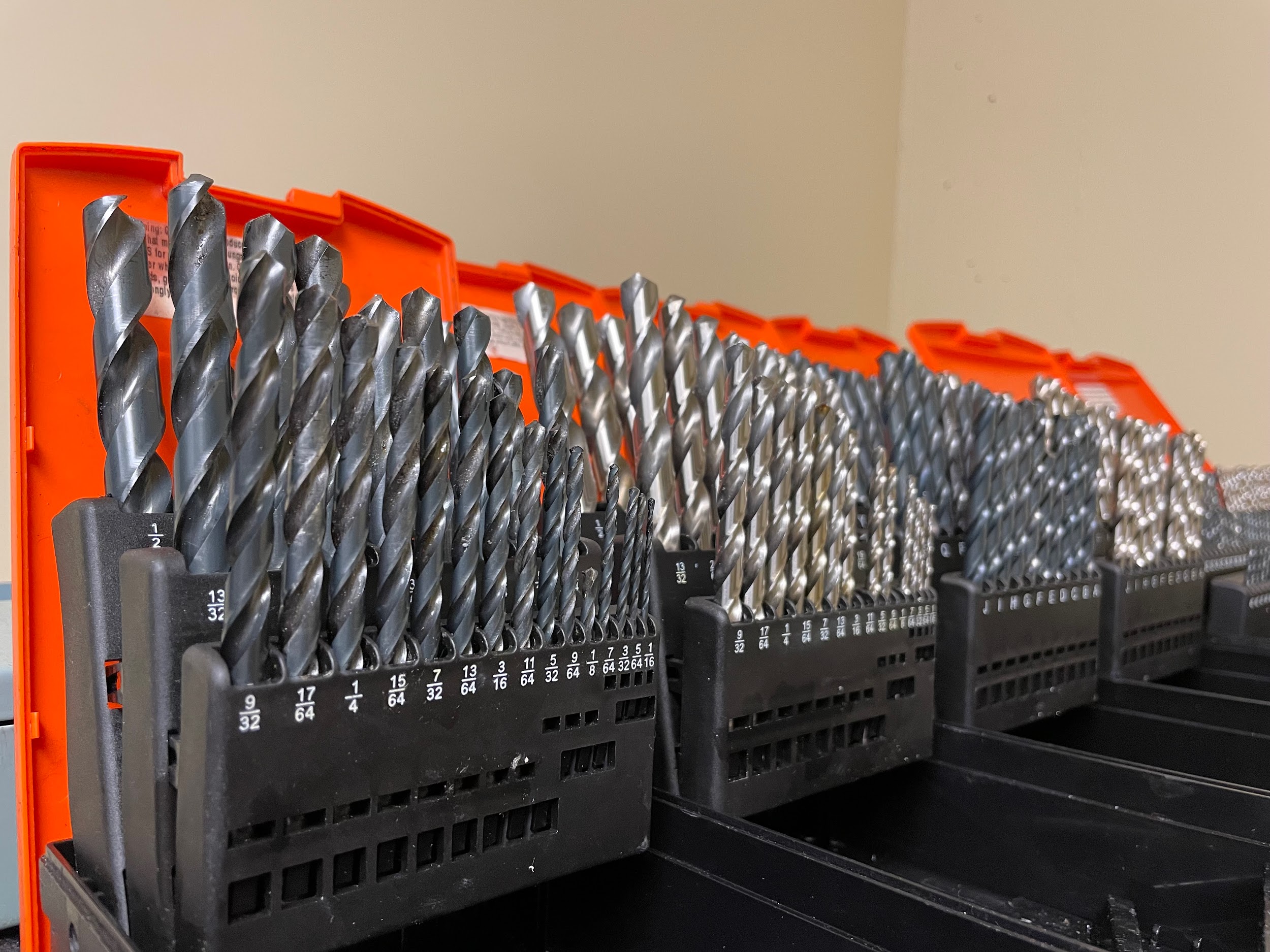
The modern twist drill was invented in the 1860s by Stephen A. Morse (Modern Machinery, 1899). The twist drill has a single job. It creates holes, and it is the most efficient tool for this job. Twist drills come in a variety of sizes identified by fractional, numerical, letter, and metric indicators. Twist drills also come in many different styles with the jobber and screw machine being two of the most common. Twist drills come in different materials, most commonly high-speed steel, cobalt, and carbide. For each material, there are also many different coatings.
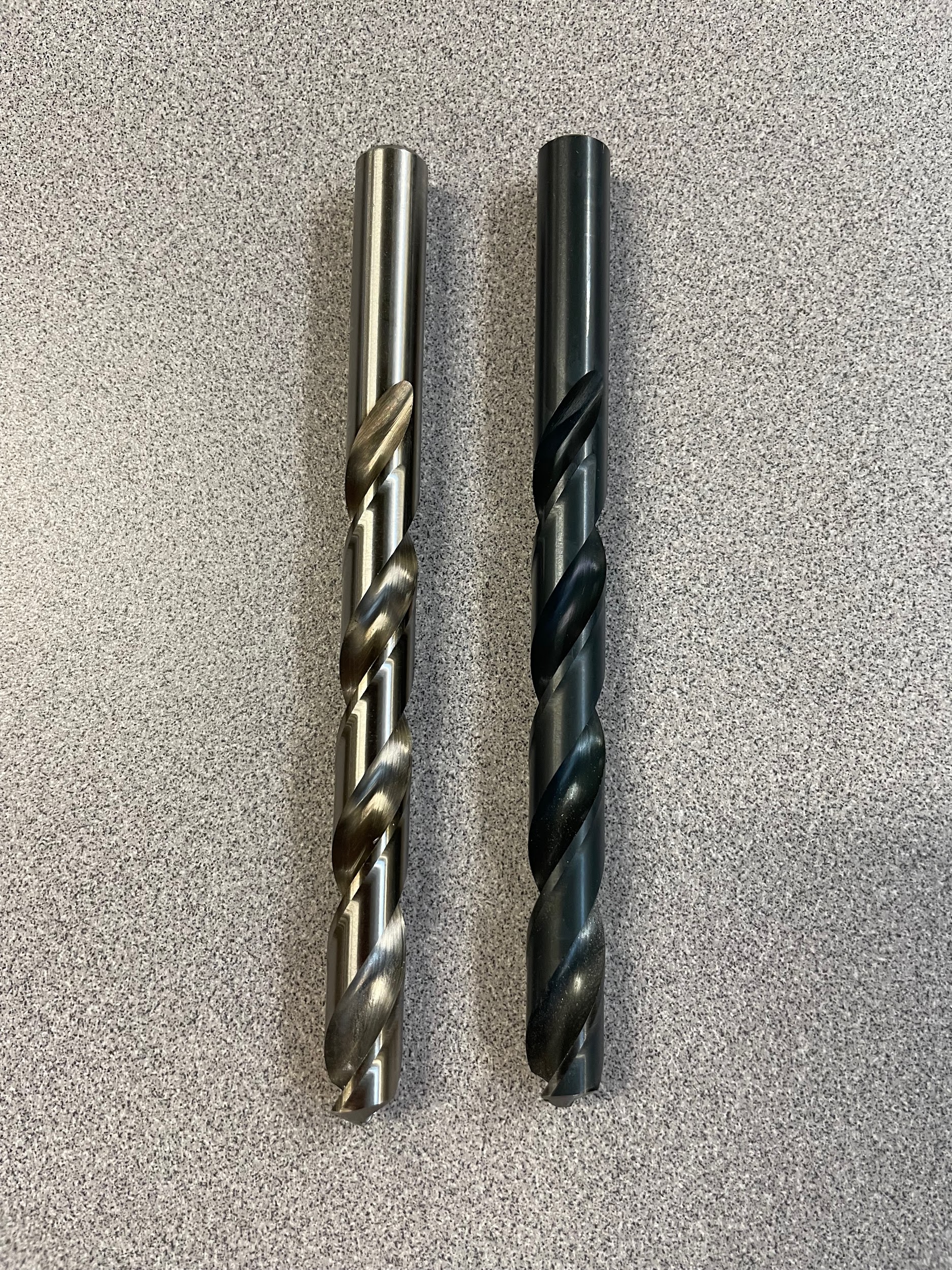
Coatings on a twist drill aid in friction reduction inside the flutes where the chips ride. This friction creates heat and can break down the cutting edge of the drill. Coatings are often work material specific, meaning that they are designed for use with specific materials. Non-ferrous materials like aluminum have a tendency to stick to black oxide and titanium nitride coatings.
A twist drill consists of three sections, the shank, the body, and the tip. Each of these sections contains different features of the twist drill. When all of these features are accurate and working together, a good hole is produced. If one or more features are damaged, worn, or out of tolerance, an inferior hole is created.
Author’s Tip
About coatings… for the average person buying twist drills, they are a gimmick. They aren’t going to help you out much if you are a hobbyist using a hand drill at home. Coatings and different materials don’t offer any protection from misuse which is common among home users and beginners. Some twist drills will allow you to cut harder work materials or cut at faster spindle speeds. Coatings allow you to spin the tool a little faster and offer longer tool life in optimal conditions. Faster spindle speeds mean nothing without an increase in feed rate. Beginners generally don’t have the experience necessary to feed twist drills at the proper rate. For these reasons, I recommend home drillers stick to uncoated high speed steel tools for cutting nonferrous materials, and black oxide coated high speed steel tools for cutting steel. The black oxide twist drills are the same price as the uncoated bits and do help with friction in steels.
Twist Drill Components
The twist drill is one of the simplest tools in the industry as well as one of the most efficient. A machinist should know the twist drill nomenclature and understand the function of its various parts in order to effectively communicate with coworkers. The names of the components of a drill are often used on other tools with similar features, making the twist drill a good tool to examine.
Shank
The shank of the bit is the area that is held in a tool holding device. The shank needs to be free of oil, chips, burrs, and other surface contaminants that might not allow for proper tool holding. A few common types of twist drill shanks are straight, taper, and reduced shank.
Straight Shank
A straight shank on a twist drill is the most common. The shank is the same diameter as the advertised twist drill size. twist drills that come in standard indexes are under ½” in size and are of the straight shank variety. Twist drills that are under ½” in size can be adequately gripped by a drill chuck without spinning or slipping.
Taper shank
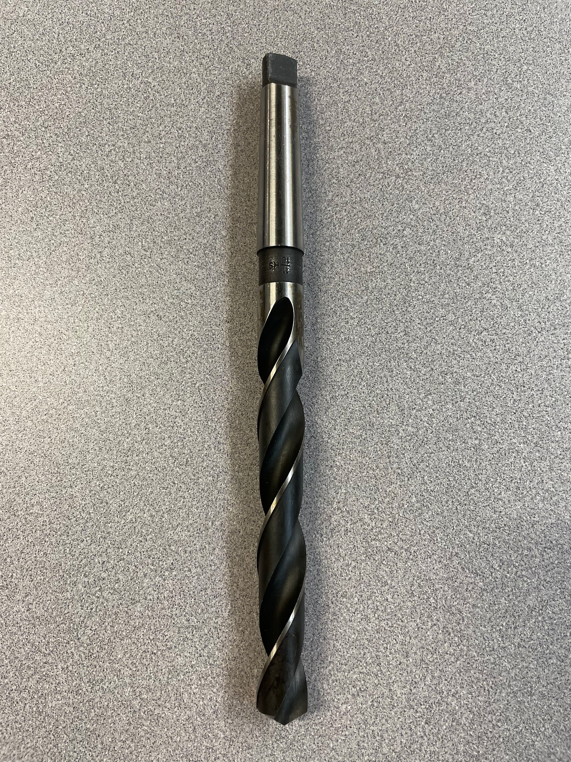
Some twist drills have a Morse taper shank. This type of shank accommodates a wedging action that holds the bit more securely than a straight shank and a drill chuck. This stronger hold on the bit can be used for any size twist drill but is often reserved for larger twist drills that would have a tendency to slip in a drill chuck or would have a shank that is out of the drill chuck’s capacity. Twist drills that are over ½” are well suited for taper shanks.
Reduced shank
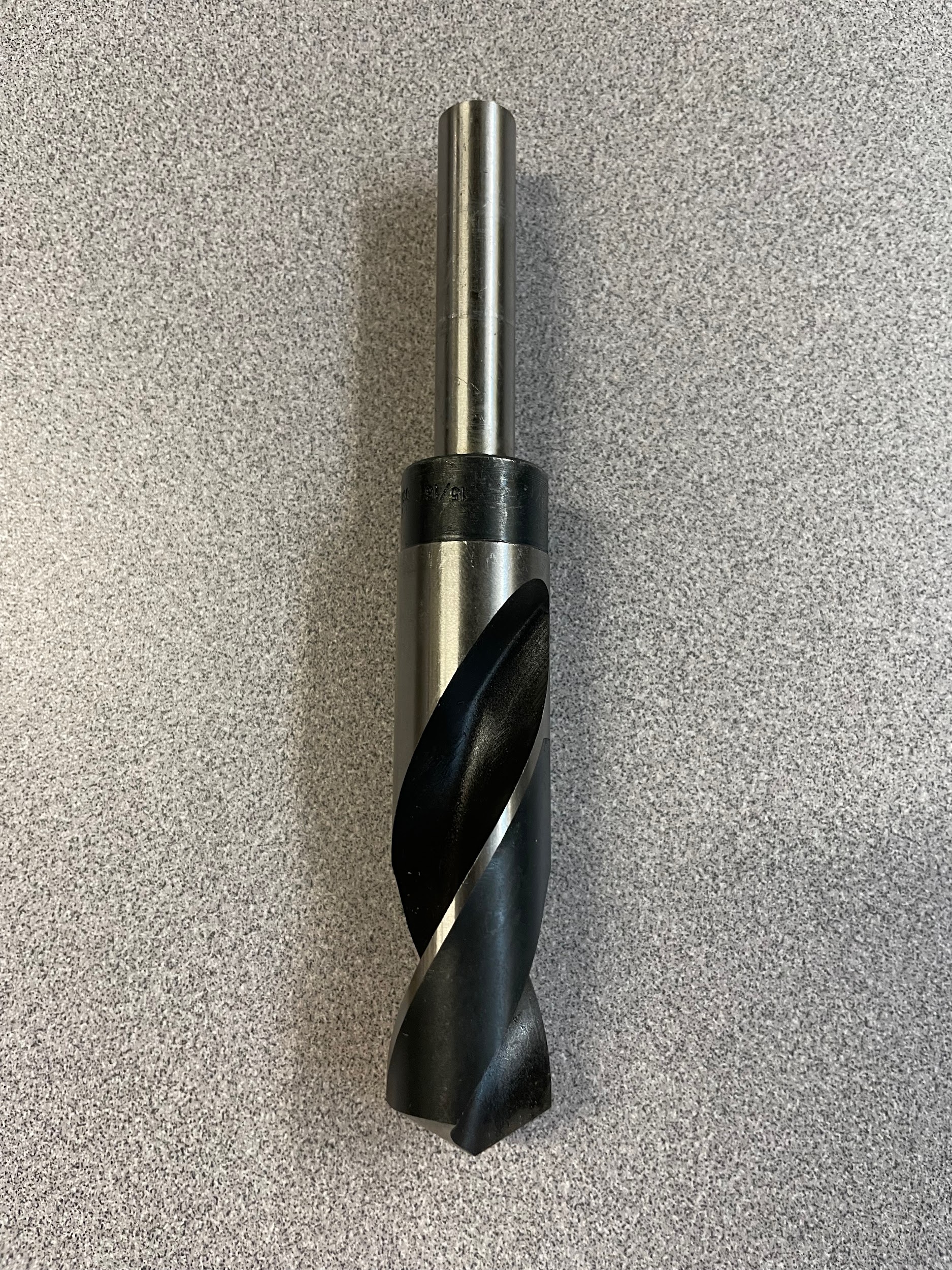
Reduced shank twist drills are made for the occasion when a twist drill is needed that exceeds the size the drill chuck can accept and/or the machine being used won’t accept Morse tapers. These special bits have a ½” shank that can easily be gripped in a drill chuck or collet. Reduced twist drill sets generally come in fractional sizes from ½” to 1″ in 1/64″, 1/32″, 1/16″ or ⅛” increments.
Author’s Tip
When I find myself in a position where I need to use a reduced shank drill, I consider the limitations of my work holding options. Quality ½” drill chucks are barely adequate to hold back the torque produced by a ½ twist drill. A 1″ reduced shank twist drill has twice the cutting edge length of a ½” bit, but the same contact area on the ½” shank. This inequality often results in twist drills spinning in the chuck or chattering while hole cutting because of reduced feed to keep the bit from spinning in the chuck. Chatter is an inconsistency in chip formation caused by the tool’s inability to adequately penetrate the work during the cutting process. The best option for a lathe or a drill press would be to get a quality taper shank bit that can be held securely and fed properly. If using a milling machine, I opt to put reduced shank twist drills into a ½” collet. This gives secure tool holding to at least be able to keep the bit from chattering, but you should resist the urge to push the twist drill to its optimal cutting condition. These bits must be used with caution because the ½” shank is much weaker than a traditional straight shank or a taper shank, and can be twisted off during medium to heavy use.
Body
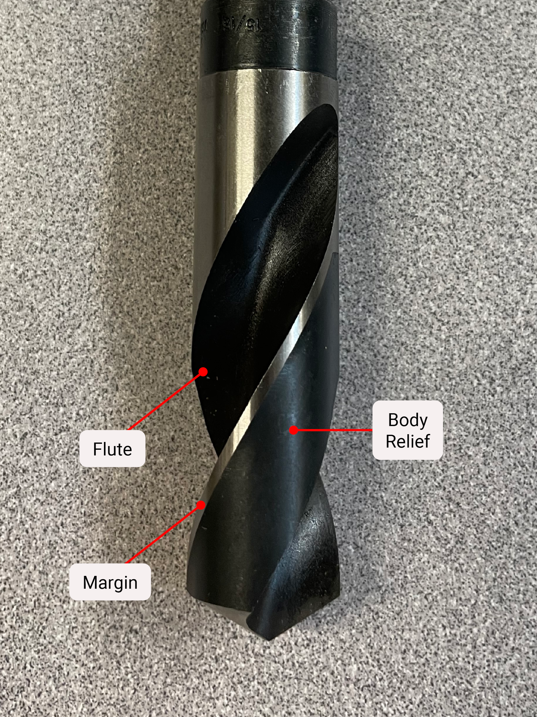
The body of the twist drill is the large center section that is recognizable by its helix. The body consists of the flutes, the body clearance, the margins, and the web.
Flute
The flute is the helical recessed area of the twist drill, angled at approximately 30 degrees to the center axis. The flutes are where the chips flow out of the hole during the cutting process. For this reason, the flutes of the drill are specifically designed in a helix, similar to an Archimedes screw. The helix of the flute can vary based on the material the twist drill is intended to cut because the helix angle also produces the rake of the cutting edge. Softer materials may be able to take advantage of a higher helix and quicker chip evacuation, while harder materials may cut better with a straighter helix.
Margin
The margin is the thin helical band around the outside of the twist drill. The margins are the furthest outside diameter of the twist drill and give the bit stability while in the cut. The margins are often mistaken for cutting edges by people outside the industry. Margin wear is often the most overlooked when drill inspection is being performed. When margins wear, the operator will experience loud screeching without much of a hole being cut. That is because the margin at the end is worn into a taper instead of being straight. That worn margin makes the tip cut a smaller diameter that the body of the twist drill can’t fit into. Essentially, it’s like trying to pound a tapered plug into a round hole.
Body clearance
The body clearance is the area right behind the margin. This area gives clearance so there isn’t a large amount of friction built up by too much of the twist drill rubbing inside a hole. The body clearance needs to be substantial to give the bit strength and stability. Low quality twist drills often have very little material in this area and are prone to drilling crooked holes because of the flex of these lightweight twist drills.
Web
The web is a small, thin amount of material that connects one half of the body to the other. The web thickness is measured from the bottom of one flute to the bottom of the other flute. Generally, the web is thicker near the base and thinner by the tip. Similar to a pyramid, it needs more support at the bottom and less at the top. The web culminates at the end of the twist drill with a feature called the chisel point.
Tip
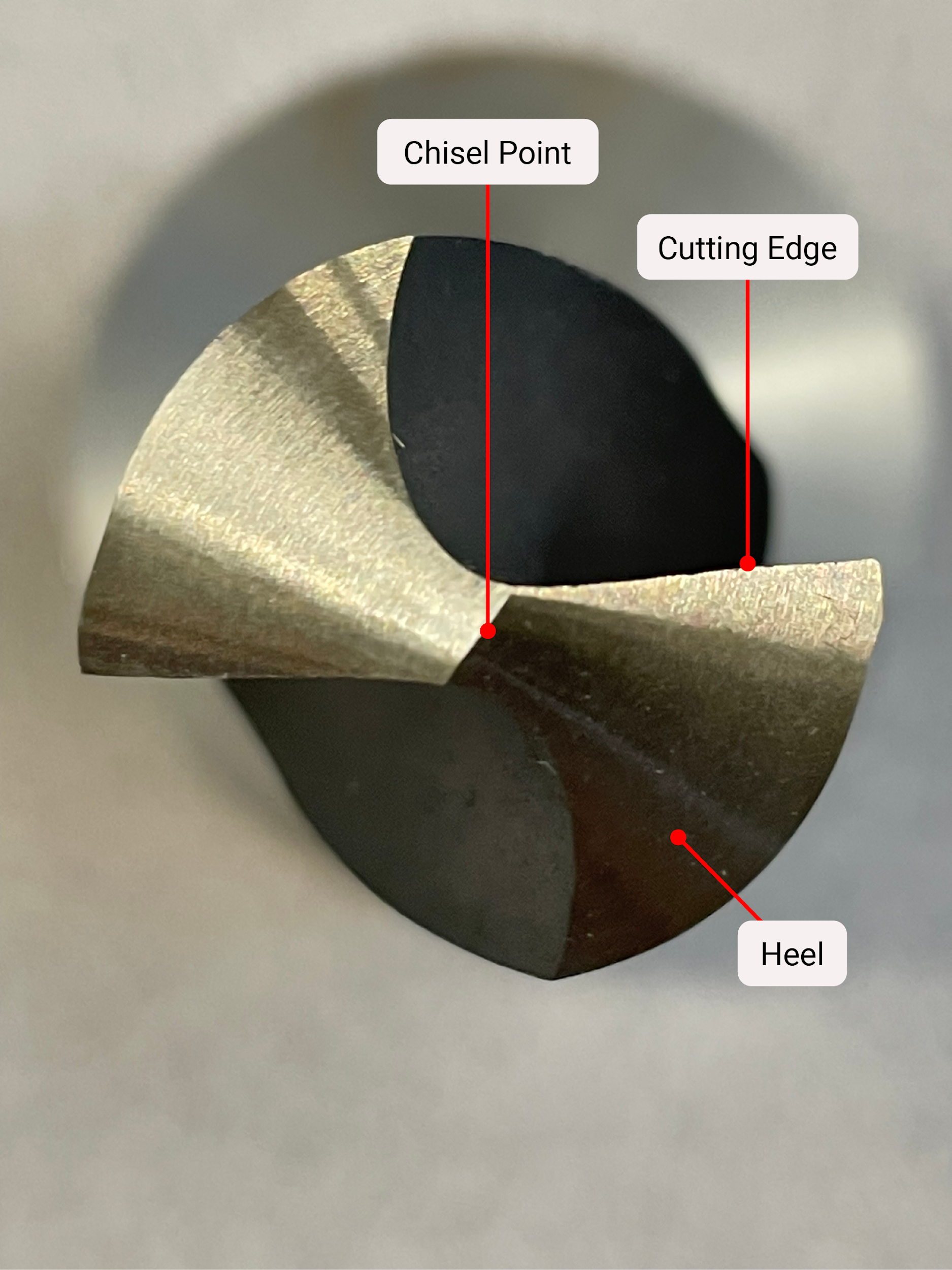
The tip of a twist drill is the business end. The point where the cutting happens. The tip consists of the chisel point, the cutting edges and the heel.
Chisel point
The chisel point is formed by the web meeting the tip of the twist drill. The chisel point helps to keep the twist drill centered as the drill enters the cut. It pushes material outward to be cut by the cutting edges. It is important to note that the chisel point doesn’t really cut any material, it just displaces material. On a correctly ground twist drill the chisel point is a nice straight line at about a 135 degree angle to the cutting edge. On some drills, such as screw machine drills, the chisel point is split to give an almost nonexistent chisel point. The effect of splitting the point is to help the bit start into the material by eliminating the chisel point. Often if twist drills get over-sharpened and become too short, the chisel point will make up too much of the drill tip and the cutting will become inefficient. Not only will the twist drill be inefficient, but it will usually cut oversized and produce more heat than usual.
Cutting edge
The cutting edge runs from the end of the chisel point to the margins. The two cutting edges form the twist drill tip angle. For standard jobber drills, this is 118 degrees. For screw machine drills, this will be 135 degrees. In general terms, the smaller the tip angle, the softer the material needs to be. Harder material will be better cut with a wider angle. This is because the tip of the smaller angle is more easily compromised by hard material. The cutting edge is where the chip is formed that flows up the helix of the flute. The angle of the helix defines the amount of positive rake the cutting edge will have. The area of the flute right after the cutting edge is where the chip rides after being cut from the workpiece and is the point of most friction and heat production. On a properly sharpened twist drill, the cutting edges will be equal to one another, both in the angle from the center axis of the twist drill and in length. The length of the cutting edge can be measured accurately from the intersection of the cutting edge and the margin to the intersection of the chisel point and the flute. Even a few thousandths can make the twist drill imbalanced and make it cut to a larger size than desired.
Heel
The heel is the area directly behind the cutting edge and continues to a point at the edge of the opposing flute. The heel creates the adequate relief clearance required for the cutting edges to engage in the work. In general terms, the relief can be greater when preparing drills for cutting softer materials, allowing them more clearance for aggressive cutting and avoiding sticking and galling. For harder materials the relief should be less so as to provide as much strength and mass for heat distribution. Also, cutting harder materials will not be as aggressive, so maximum clearance isn’t necessary. For general purpose jobber twist drills, the relief is about 10 degrees.
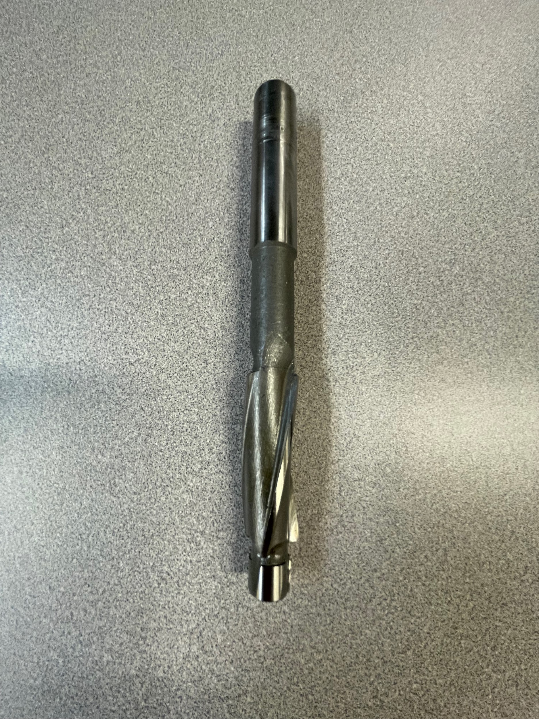
Reamer
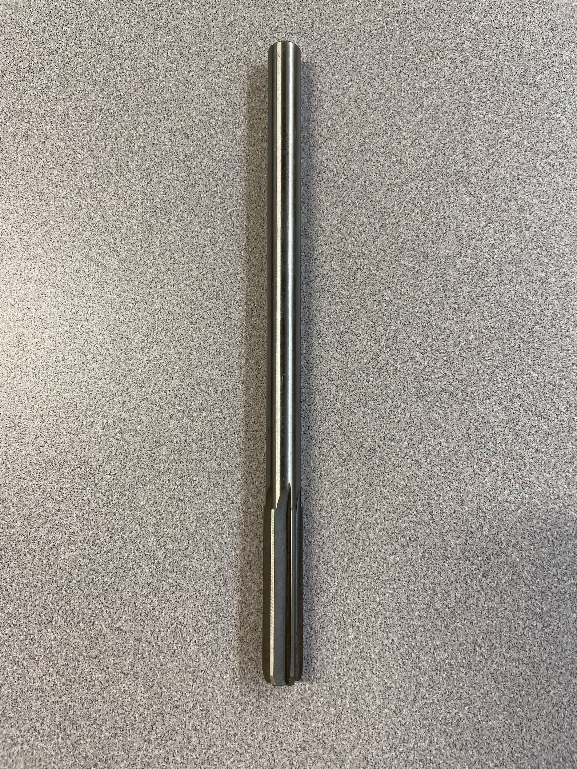
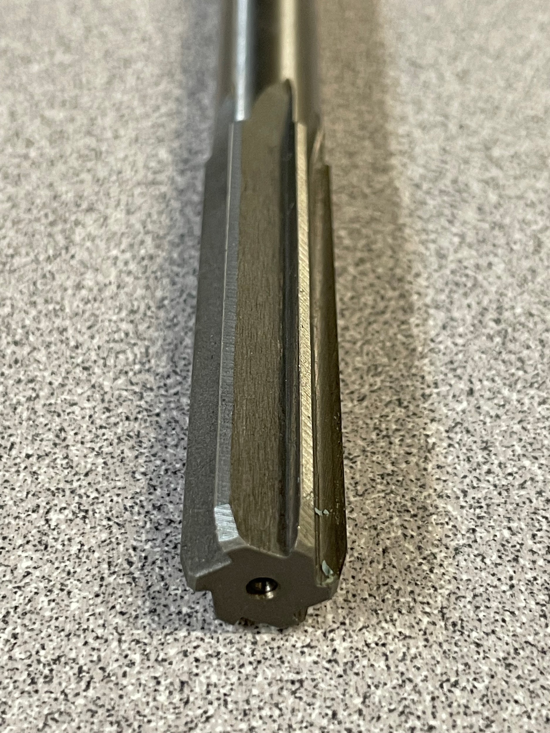
A reamer is similar to a twist drill in that they are used to create a hole; however, the hole created with a reamer is of much tighter tolerance and surface finish. A reamer is also a secondary hole process, meaning there needs to be a hole in place first before the reamer can be used to slightly enlarge its size. Reamers generally have much longer shanks than twist drills. This lengthened shank increases the reamer’s flexibility and aids it in aligning with the initial hole. The body of a reamer has many more flutes than a twist drill. The flutes are often straight but can also be set to a helix. The point of the reamer has chamfered edges that are used to cut and create the size of the reamed hole. Some reamers, such as a tapered reamer, cut on the body of the tool rather than the tip.
Tap
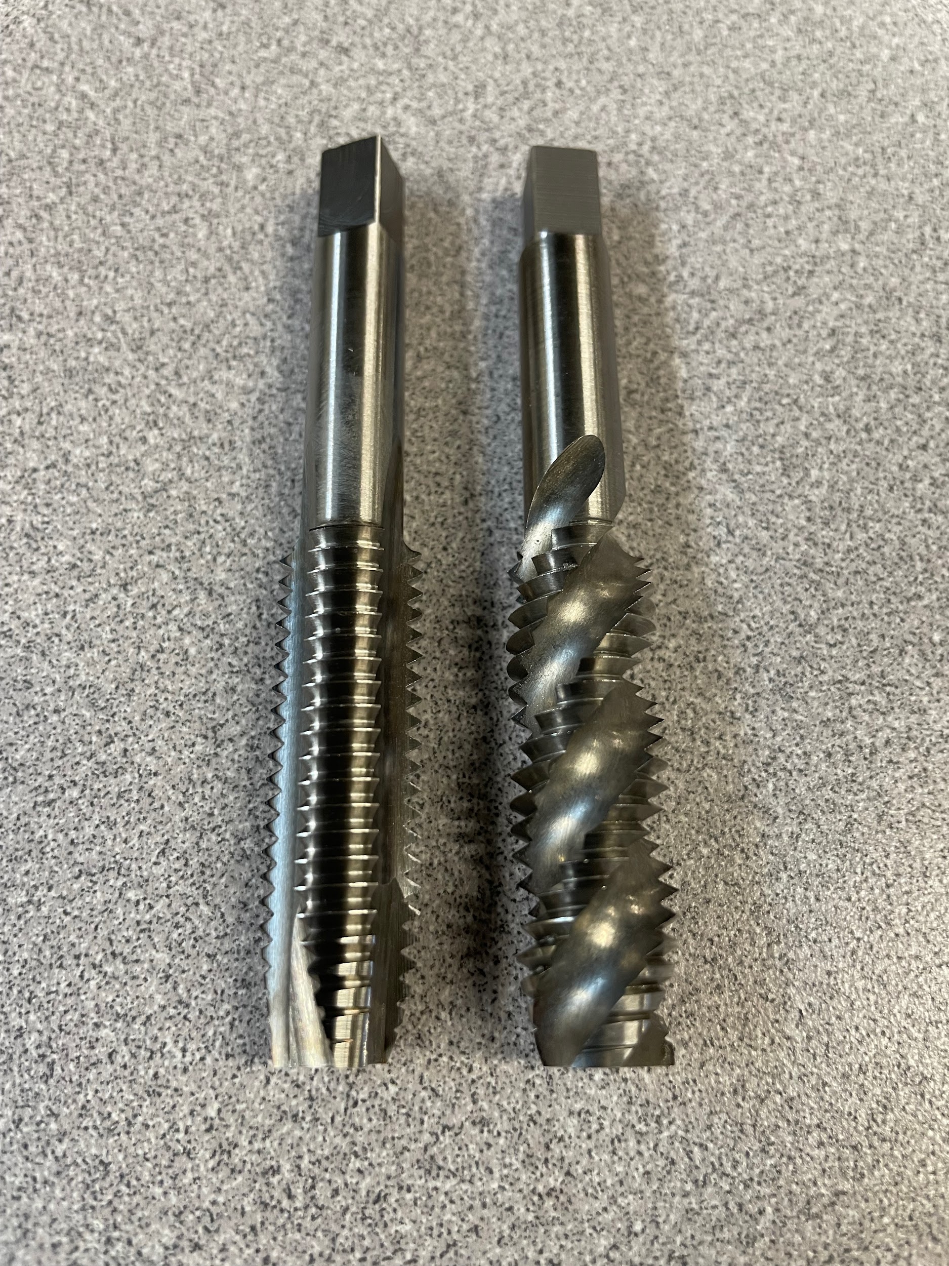
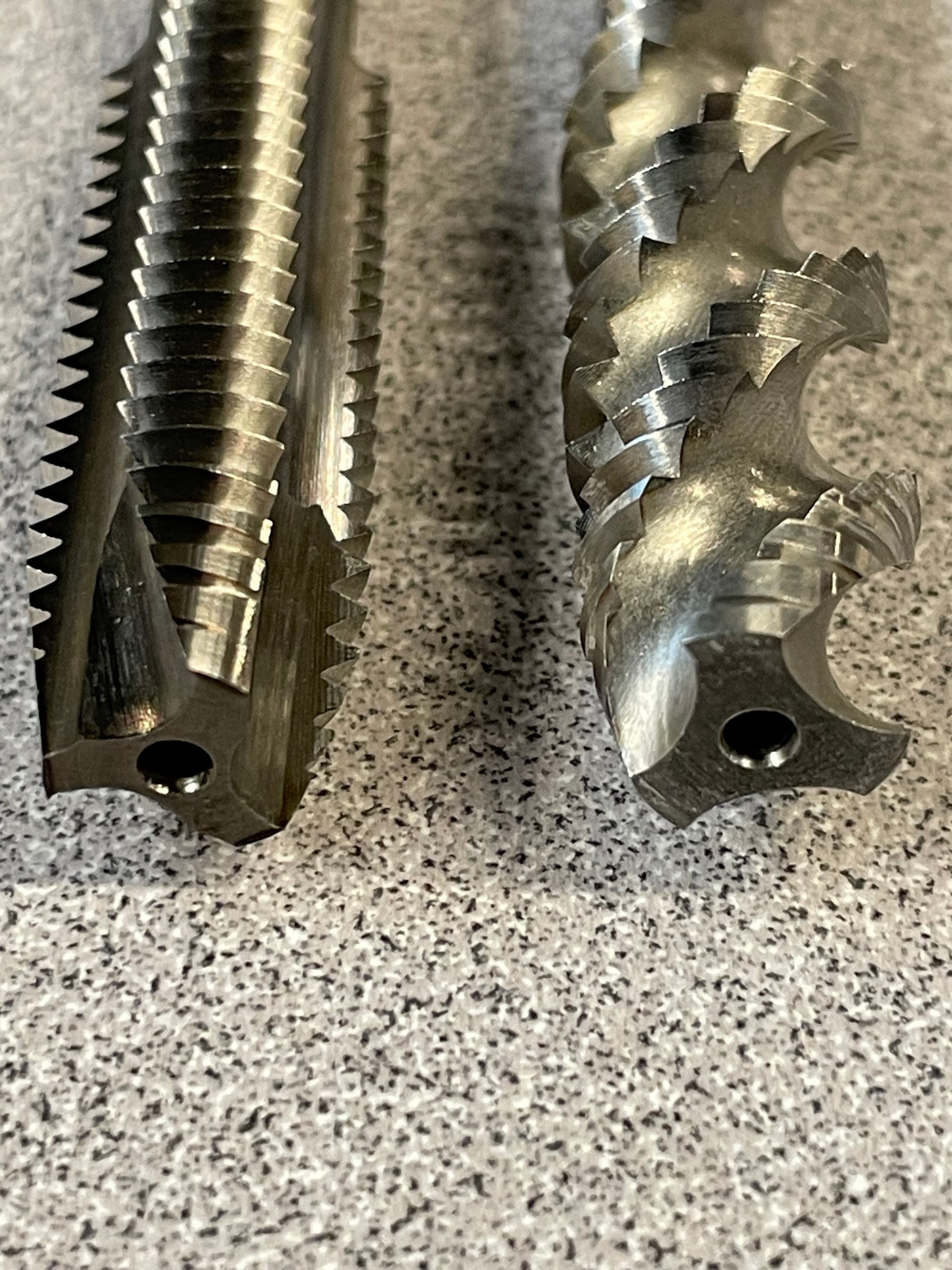

A tap is a cutting tool used to create internal threads inside a hole. This is another secondary tool that requires a hole to be in position before the tapping process can take place. Taps are designated by size and pitch, meaning the outside diameter, and the number of threads in an inch (TPI). There are many different types of taps that can be used in machines including spiral point, spiral flute, plug, and bottoming to name a few. What these taps all have in common is their general construction. Taps have a short straight shank that commonly has a square on top. This square on the shank is used to drive the tap. The body of the tap looks much like a bolt, although with flutes to clear the chips created by the cutting edges. The cutting edges of the tap are only located at the tip of the tap. These cutting edges can be recognized by a tapered section at the point. The cutting edges may also have another ground portion inside the flute. This is the only portion of the tap that cuts metal. The rest of the threads on the tap are used to keep the tap straight and in time with the pitch of the tap.
Countersink
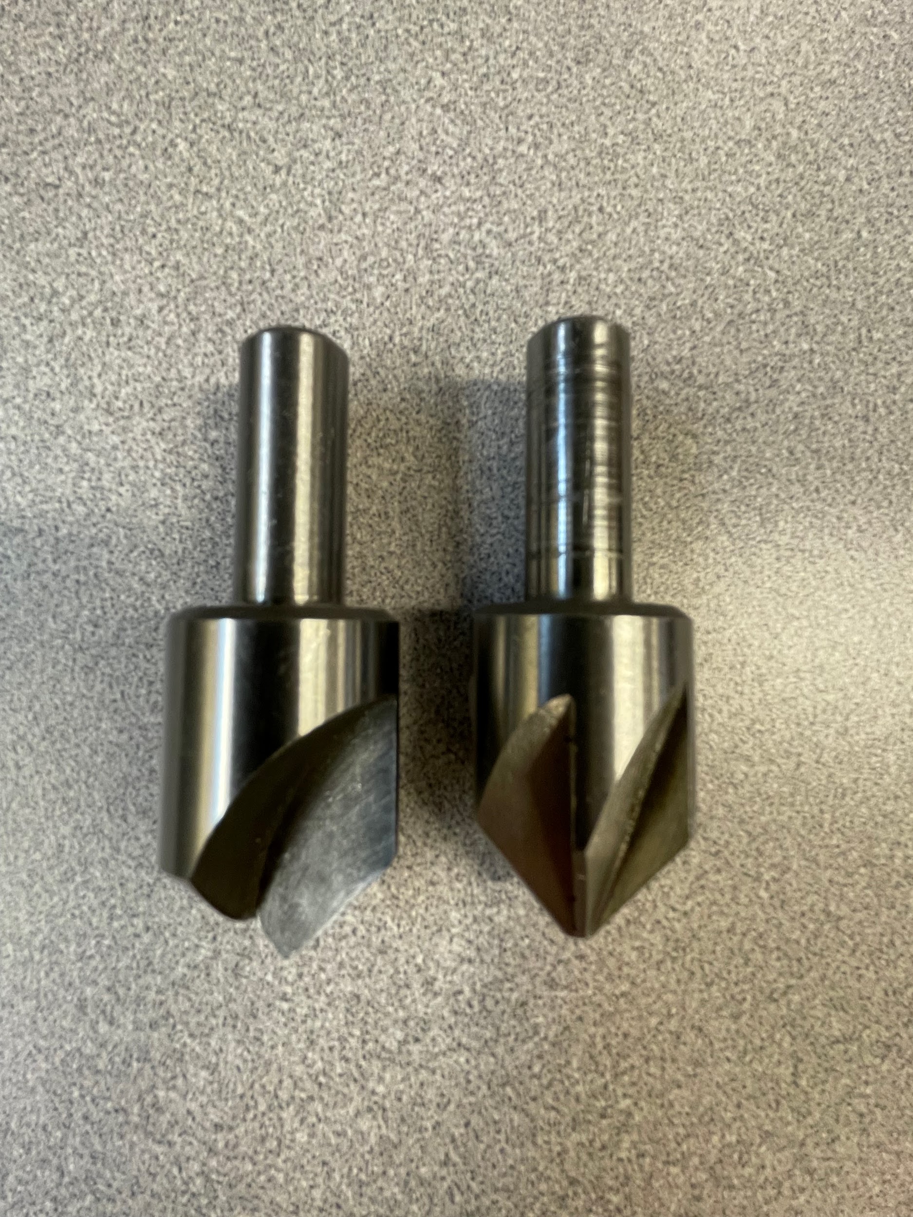
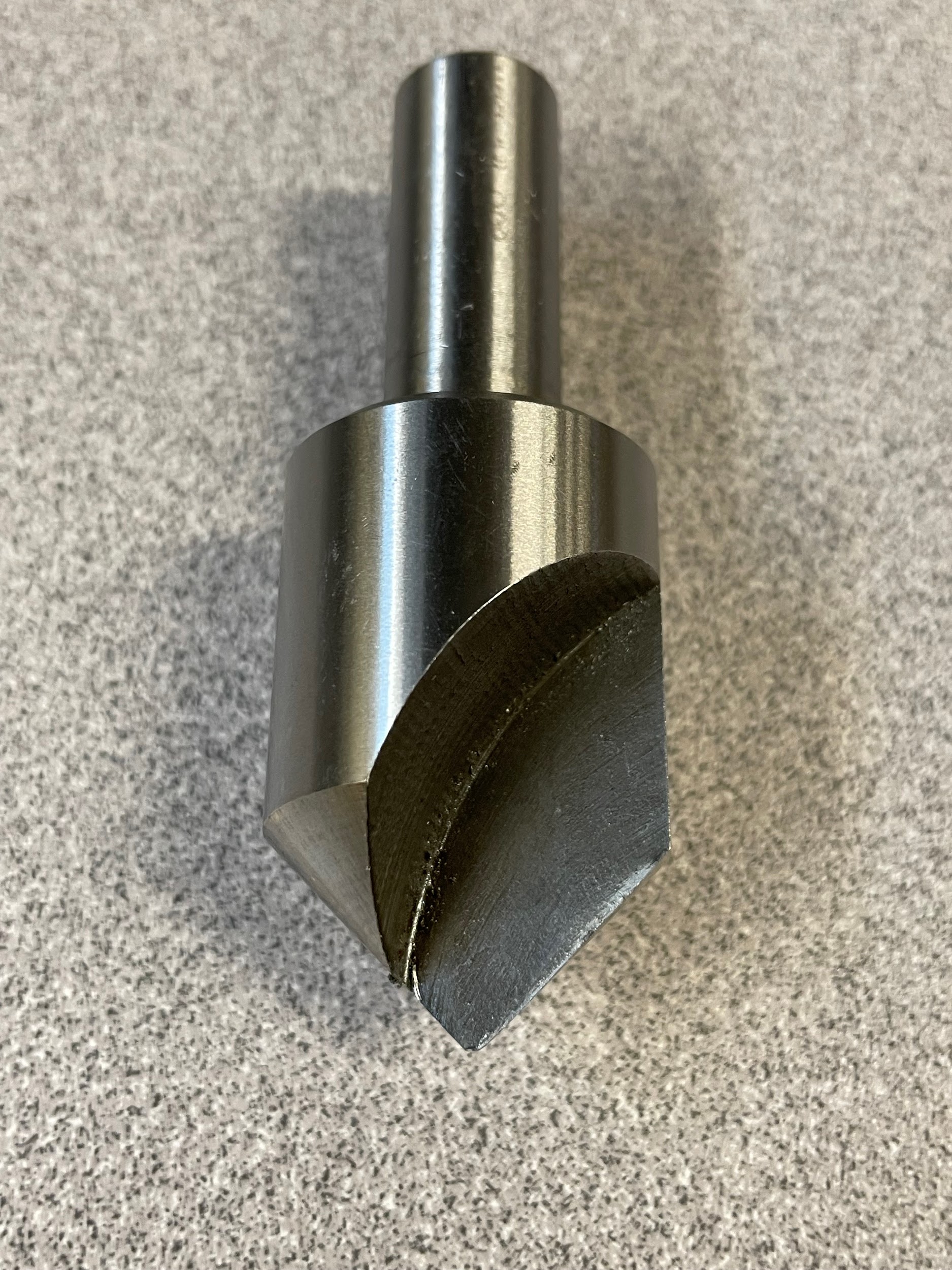
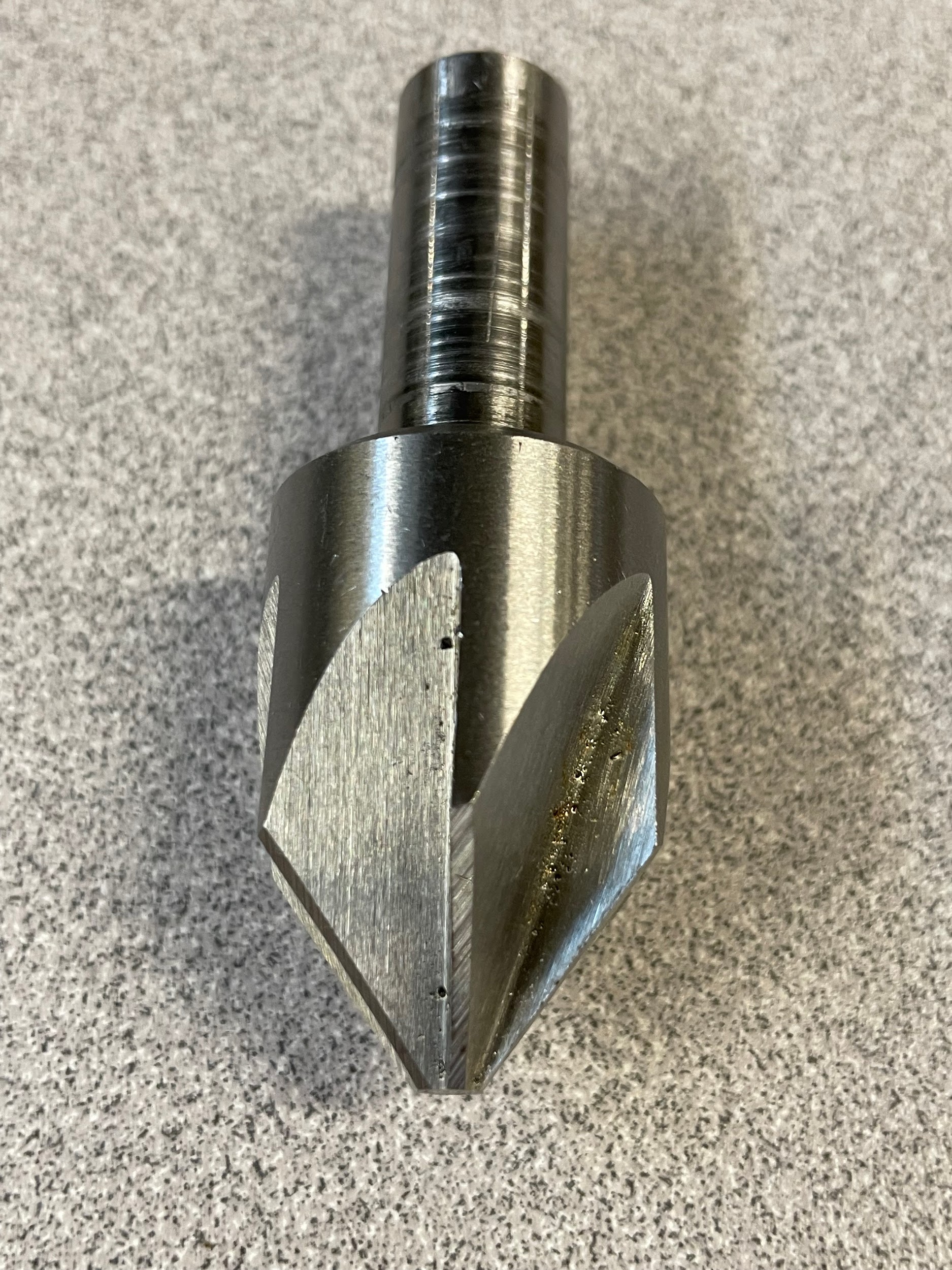
A countersink is used to create a conical cut at the top of a hole. This conical cut is used to recess flat headed fasteners or chamfer holes at various angles. Countersinks can be of many different designs, zero flute, single flute and multi- flute are just a few. They also come in many different angles. Most common are 82-degree, 90-degree and 60-degree. The tool often has a shank smaller than the cutting head and comes in sizes based on the largest diameter countersink that can be created. The cutting action happens only on the angled tip of the tool.
Counterbore
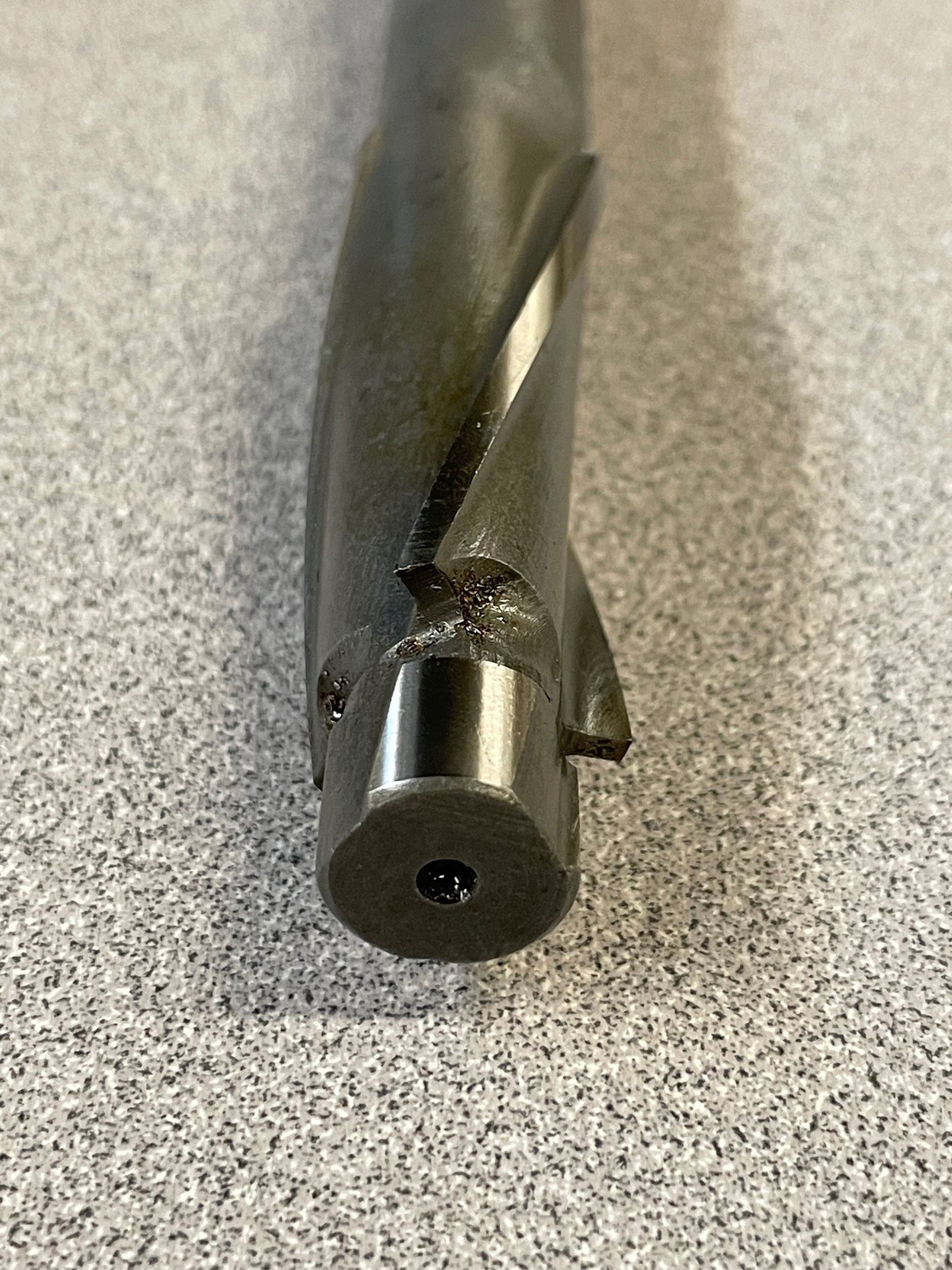
A counterbore is used to create a cylindrical cut at the top of a hole. This cylindrical cut is generally to recess cap screw fasteners. This tool has a long shank attached to the body of the counterbore. The body has multiple helical flutes that transport chips away from the cutting zone. The tip of the tool features the cutting edges that match the size of the counterbore, as well as the pilot. The pilot is a cylindrical button on the tip of the cutting tool that closely fits inside the hole being counterbored. Because the cutting edges of this tool are flat, it needs help to stay centered. The pilot provides the stability the counterbore needs.
Attributions
- Figure 8.46: Center finder kit by Micky R. Jennings, courtesy of Wenatchee Valley College, for WA Open ProfTech, © SBCTC, CC BY 4.0
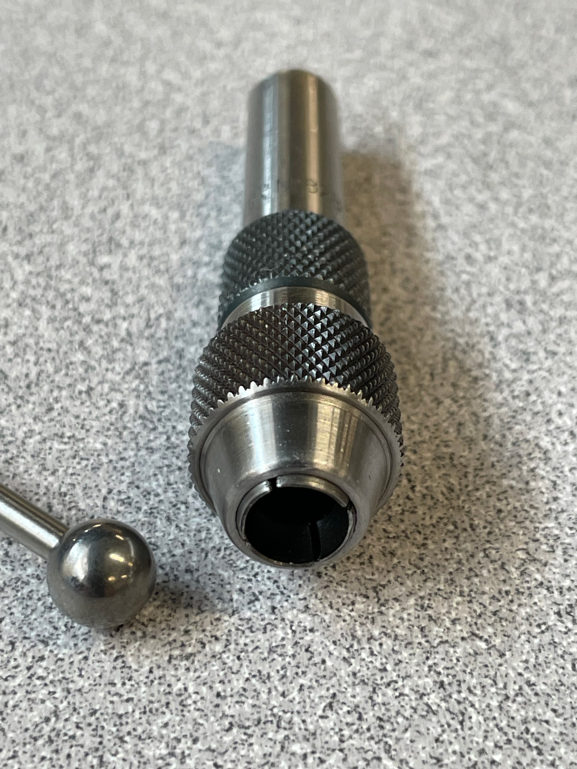
- Figure 8.47: Center finder socket view by Micky R. Jennings, courtesy of Wenatchee Valley College, for WA Open ProfTech, © SBCTC, CC BY 4.0
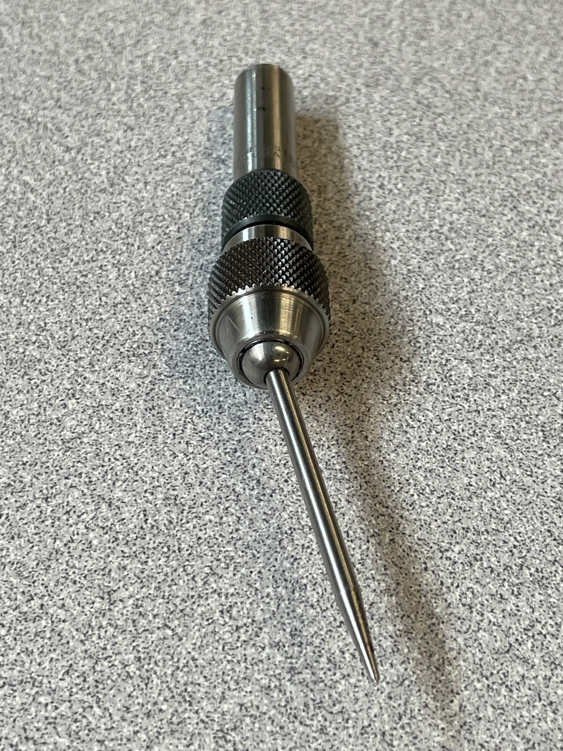
- Figure 8.48: Pointer attachment in center finder by Micky R. Jennings, courtesy of Wenatchee Valley College, for WA Open ProfTech, © SBCTC, CC BY 4.0
- Figure 8.49: Center drills by Micky R. Jennings, courtesy of Wenatchee Valley College, for WA Open ProfTech, © SBCTC, CC BY 4.0
- Figure 8.50: Closeup of center drill tip by Micky R. Jennings, courtesy of Wenatchee Valley College, for WA Open ProfTech, © SBCTC, CC BY 4.0
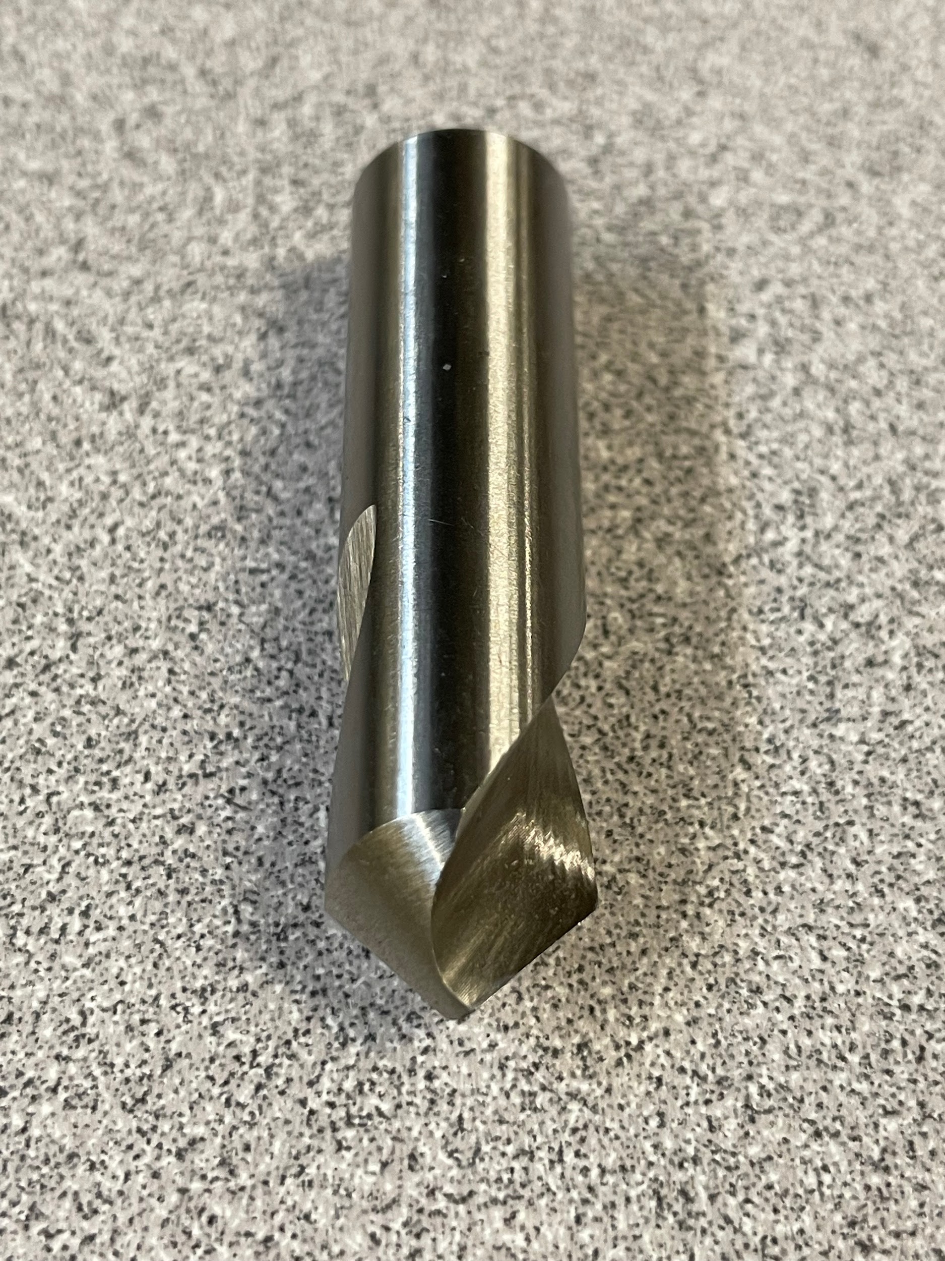
- Figure 8.51: 90-degree spot drill by Micky R. Jennings, courtesy of Wenatchee Valley College, for WA Open ProfTech, © SBCTC, CC BY 4.0
- Figure 8.52: Spot diameter – drill press by Micky R. Jennings, courtesy of Wenatchee Valley College, for WA Open ProfTech, © SBCTC, CC BY 4.0
- Figure 8.53: Spot diameter with chisel point – drill press by Micky R. Jennings, courtesy of Wenatchee Valley College, for WA Open ProfTech, © SBCTC, CC BY 4.0
- Figure 8.54: An array of twist drills. by Micky R. Jennings, courtesy of Wenatchee Valley College, for WA Open ProfTech, © SBCTC, CC BY 4.0
- Figure 8.55: Two jobber twist drills by Micky R. Jennings, courtesy of Wenatchee Valley College, for WA Open ProfTech, © SBCTC, CC BY 4.0
- Figure 8.56: Morse taper shank twist drill by Micky R. Jennings, courtesy of Wenatchee Valley College, for WA Open ProfTech, © SBCTC, CC BY 4.0
- Figure 8.57: Reduced shank twist drill by Micky R. Jennings, courtesy of Wenatchee Valley College, for WA Open ProfTech, © SBCTC, CC BY 4.0
- Figure 8.58: Body of a twist drill labeled by Micky R. Jennings, courtesy of Wenatchee Valley College, for WA Open ProfTech, © SBCTC, CC BY 4.0
- Figure 8.59: Tip of a twist drill labeled by Micky R. Jennings, courtesy of Wenatchee Valley College, for WA Open ProfTech, © SBCTC, CC BY 4.0
- Figure 8.60: Chucking reamer by Micky R. Jennings, courtesy of Wenatchee Valley College, for WA Open ProfTech, © SBCTC, CC BY 4.0
- Figure 8.61: Closeup of reamer tip by Micky R. Jennings, courtesy of Wenatchee Valley College, for WA Open ProfTech, © SBCTC, CC BY 4.0
- Figure 8.62: Spiral point and spiral flute taps by Micky R. Jennings, courtesy of Wenatchee Valley College, for WA Open ProfTech, © SBCTC, CC BY 4.0
- Figure 8.63: Close-up of spiral point, and spiral flute taps by Micky R. Jennings, courtesy of Wenatchee Valley College, for WA Open ProfTech, © SBCTC, CC BY 4.0
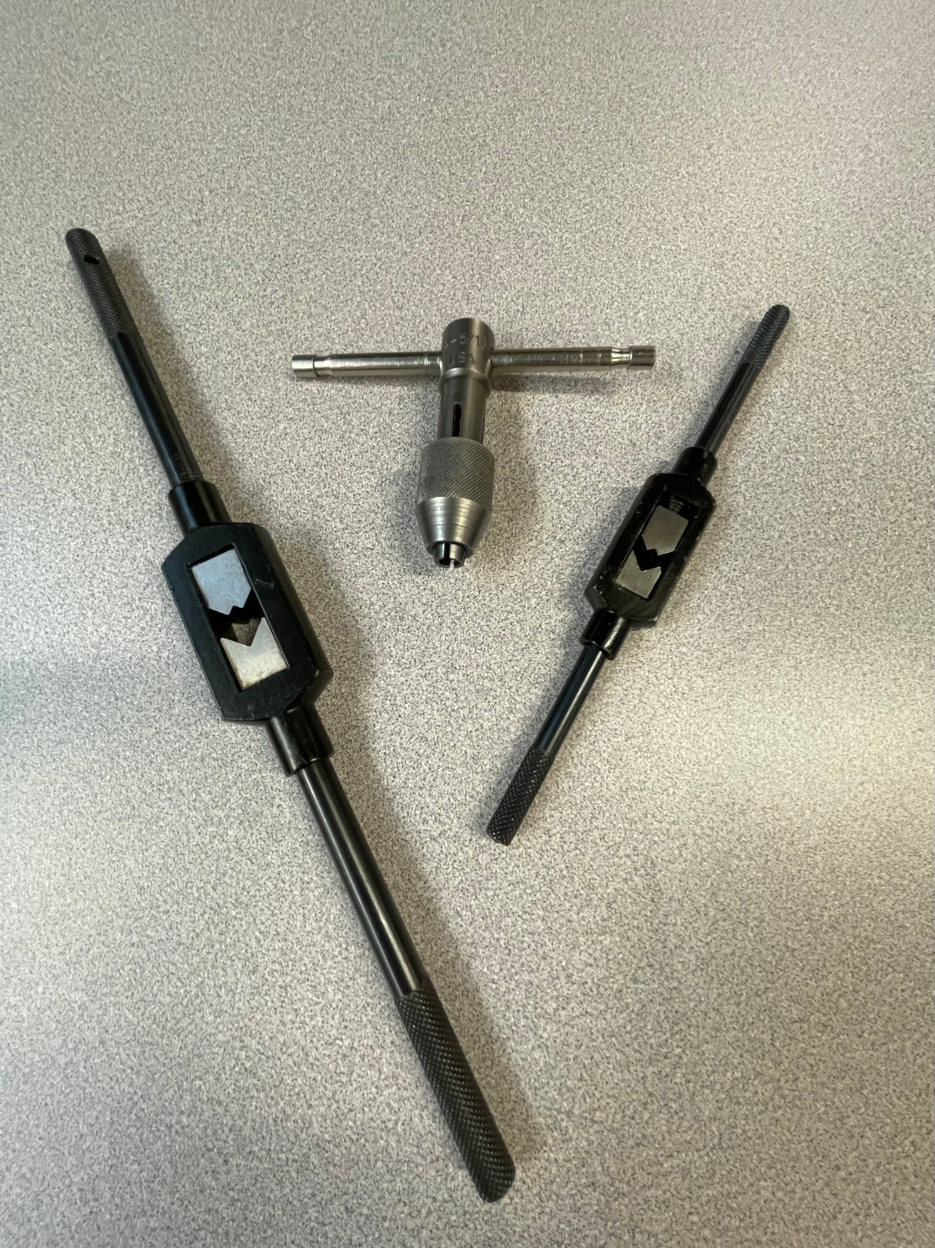
- Figure 8.64: Tap wrenches by Micky R. Jennings, courtesy of Wenatchee Valley College, for WA Open ProfTech, © SBCTC, CC BY 4.0
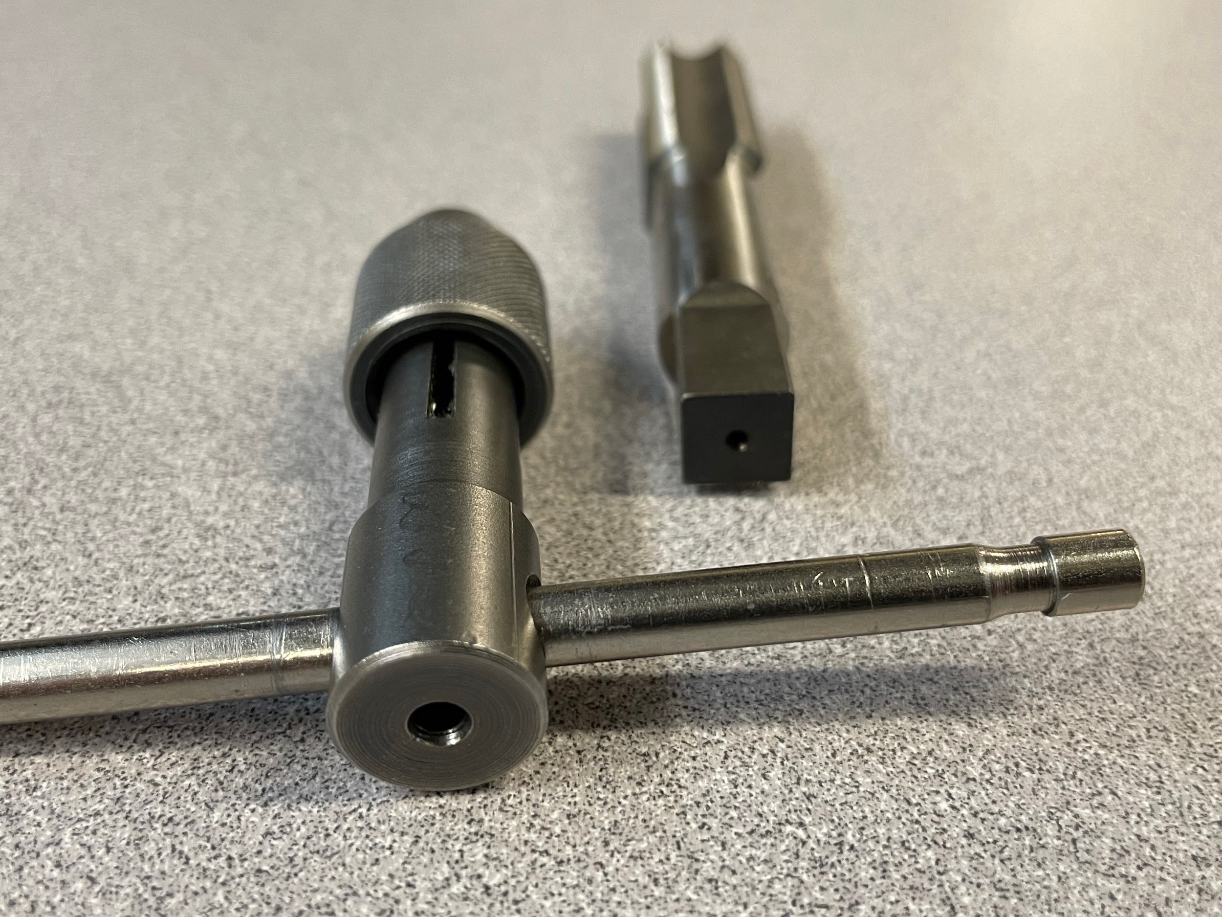
- Figure 8.65: Center in the end of tap and tee handle by Micky R. Jennings, courtesy of Wenatchee Valley College, for WA Open ProfTech, © SBCTC, CC BY 4.0
- Figure 8.66: Tap guide, tee handle, and smaller tap setup by Micky R. Jennings, courtesy of Wenatchee Valley College, for WA Open ProfTech, © SBCTC, CC BY 4.0
- Figure 8.67: Countersinks by Micky R. Jennings, courtesy of Wenatchee Valley College, for WA Open ProfTech, © SBCTC, CC BY 4.0
- Figure 8.68: Single flute countersink by Micky R. Jennings, courtesy of Wenatchee Valley College, for WA Open ProfTech, © SBCTC, CC BY 4.0
- Figure 8.69: Multi flute countersink by Micky R. Jennings, courtesy of Wenatchee Valley College, for WA Open ProfTech, © SBCTC, CC BY 4.0
- Figure 8.70: Counterbore by Micky R. Jennings, courtesy of Wenatchee Valley College, for WA Open ProfTech, © SBCTC, CC BY 4.0
- Figure 8.71: Close-up of counterbore tip by Micky R. Jennings, courtesy of Wenatchee Valley College, for WA Open ProfTech, © SBCTC, CC BY 4.0
A device used to locate the position of features on a workpiece.
A tool used to create a countersunk seat for a support center on the tailstock.
A tool used to create an initial divot for hole making procedures.
A tool used to create a hole.
The section of a tool that is gripped by tool holding devices.
A shank that is of constant uniform diameter.
A shank that has a specific precision diameter deviation.
A shank that has a diameter smaller than the tool, allowing a large tool to be held in devices that traditionally wouldn't have capacity.
A vibration in the machining process caused by a lack of rigidity, incorrect spindle speed, or incorrect feed rate.
The section of a rotational cutting tool located between the shank and the tip.
The relieved portion of the body that keeps the tool from rubbing during the machining process.
The portion of the body that allows the chips to flow away from the cut.
The small raised section of the drill body that creates the diameter and stabilizes the tool in the cut.
The material that exists from the flute on one side of a tool to the flute on the other.
The line at the center of the drill tip that connects one cutting edge to the other.
The edge at the end of a flute that creates the chip during the cutting process.
The relief on the tip of a rotational tool directly behind the cutting edge.
A tool that creates a hole of increased diametral tolerance to that of twist drills.
A tool that creates internal threads.
A conical feature at the top of a hole used to recess the head of a fastener so that it does not sit above the face of the part.
A circular, blind hole with a flat bottom. Sometimes used to recess the head of a fastener so that it does not sit above the face of the part.
