8.10 Drilling
Micky R. Jennings
Drilling is the primary machining process of creating a hole by using a twist drill. The twist drill can be turned by many different machines to create holes. The drill press is a basic machine used in a machine shop to create semi precision hole positions that are square to a surface. The main design feature of the drill press is to spin tools and apply pressure perpendicular to a workpiece; these features are essential for an accurately drilled hole.
Step by step process for drilling:
- Lay out holes to be drilled on material.
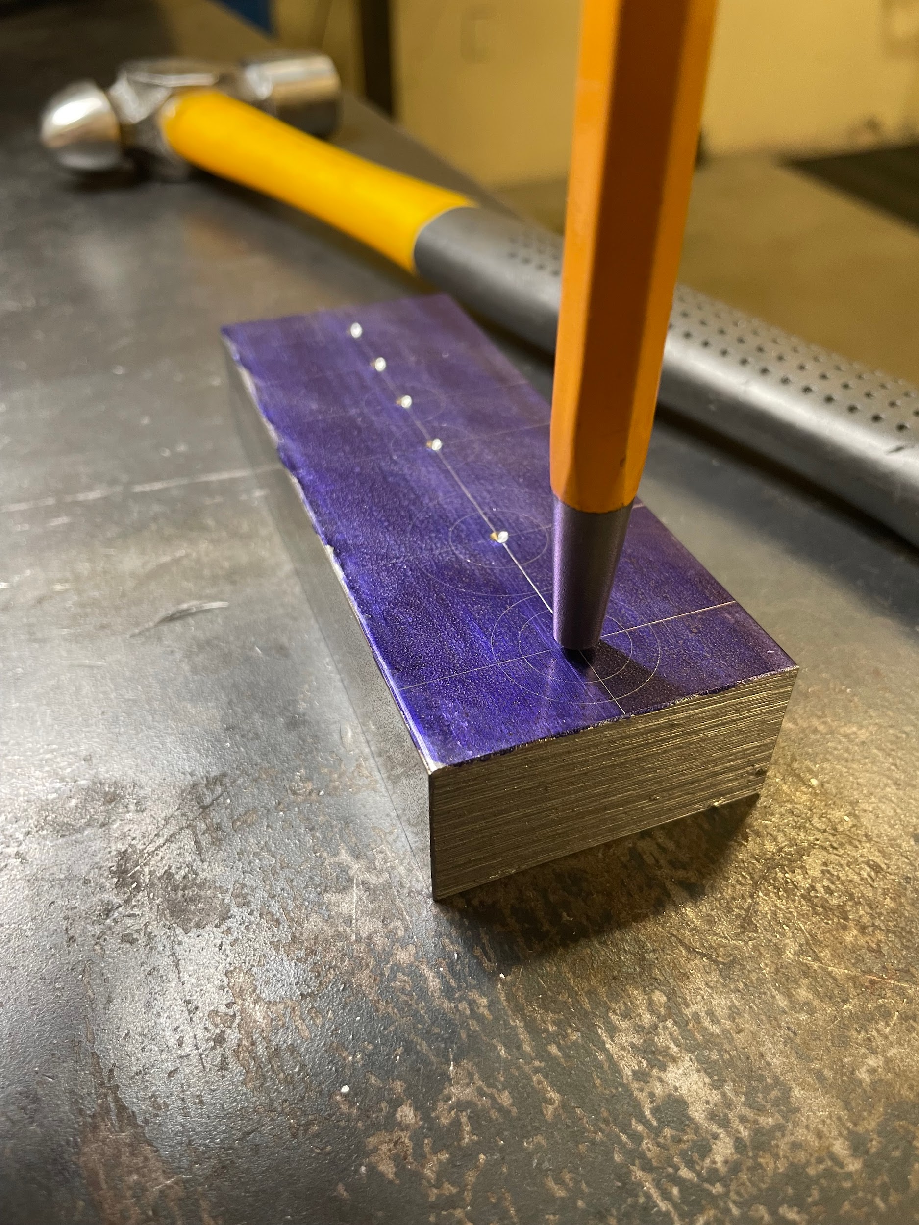
- Center punch hole locations.
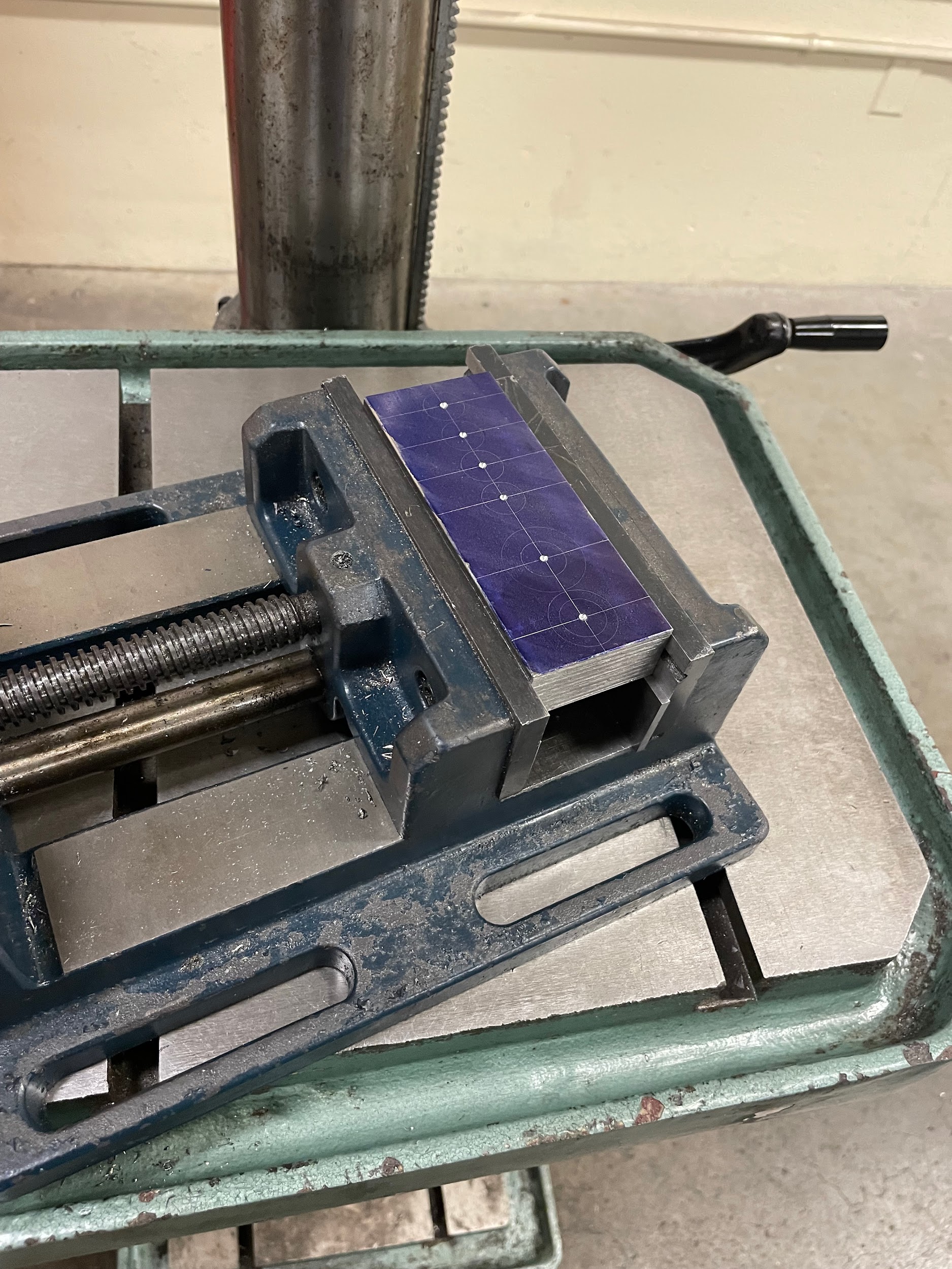
- Clamp part securely in drill vise.
- Do not clamp the vise to the table.
- Select a center drill with a pilot slightly larger than the chisel point, or a spot drill with the body larger than the chisel point.
- Mount the tool in a drill chuck.
- Adjust the table height or position.
- Calculate and select the spindle speed for the tool that will be used to spot the hole. The spindle speed is based on the largest diameter where the tool and the workpiece meet.
- Apply a drop of oil to the center punch mark.
- Gently bring the spotting tool down to the center punched mark on the part with the right hand, while precisely positioning the vise with the left hand. Leaving the vise unclamped will allow the vise to float on the table and more precisely align with the center punch mark.
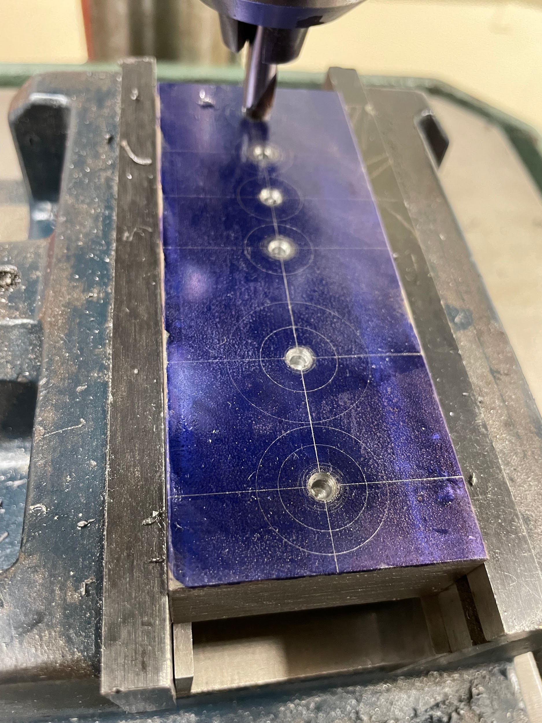
- If using a center drill, drill down to where the countersink just starts to enter the work. Be careful with the pilot; it is somewhat delicate and can be easily broken off in the part. If using a spot drill, drill down to where the diameter the tip of the spot drill makes is slightly larger than the chisel point of the drill.
- A general rule for drill press operations is to clamp work to the table or use a vise rotation stop if the cutting tool is over 1/2 inch. Above 1/2 inch, the tool’s grip on the part can become stronger than the operator’s grip on the vise. Use the spotting tool to align the vise and part during the clamping process if necessary.
- Calculate the spindle speed for the drilled hole required for the part.
- Mount the appropriate twist drill in the drill chuck.
- Add a drop of oil to the marked spot.
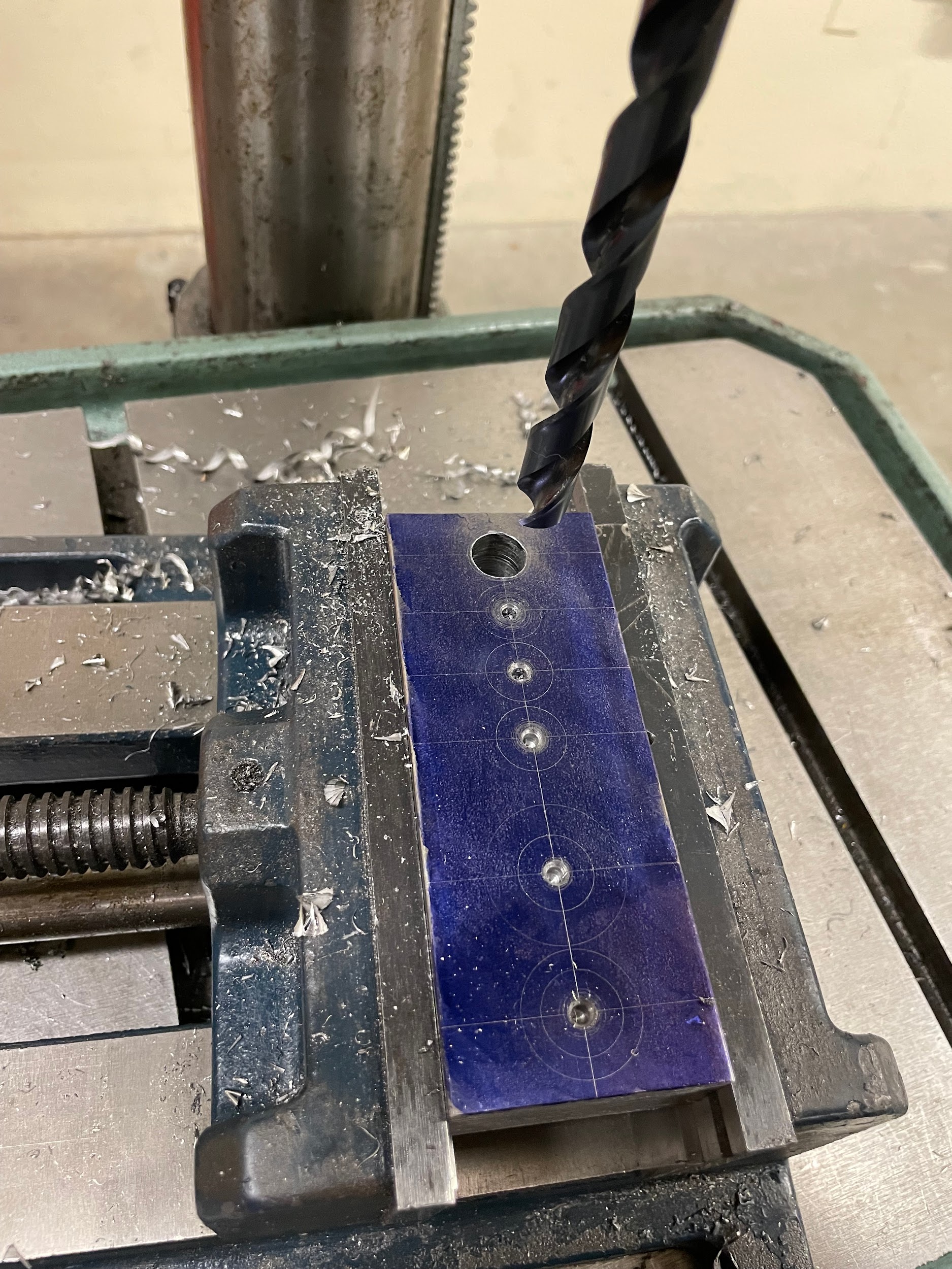
- Turn on the spindle and advance the twist drill into the marked spot.
- Push with light force to initiate the cut. Increase the force until a curling chip is formed by the cutting edge.
- Chattering may occur until the entire tool tip is in the formed hole and the bit becomes stabilized by the margins.
- Continue cutting with moderate pressure.
- Occasionally break the chips by backing the drill quickly out of the hole as they reach 3-6 inches in length, or if the chips quit coming out of the flutes.
- Ease up on the pressure as the tool begins to break through the backside of the part.
- Examine the drilled hole.
Step 1: Lay out holes to be drilled on material.
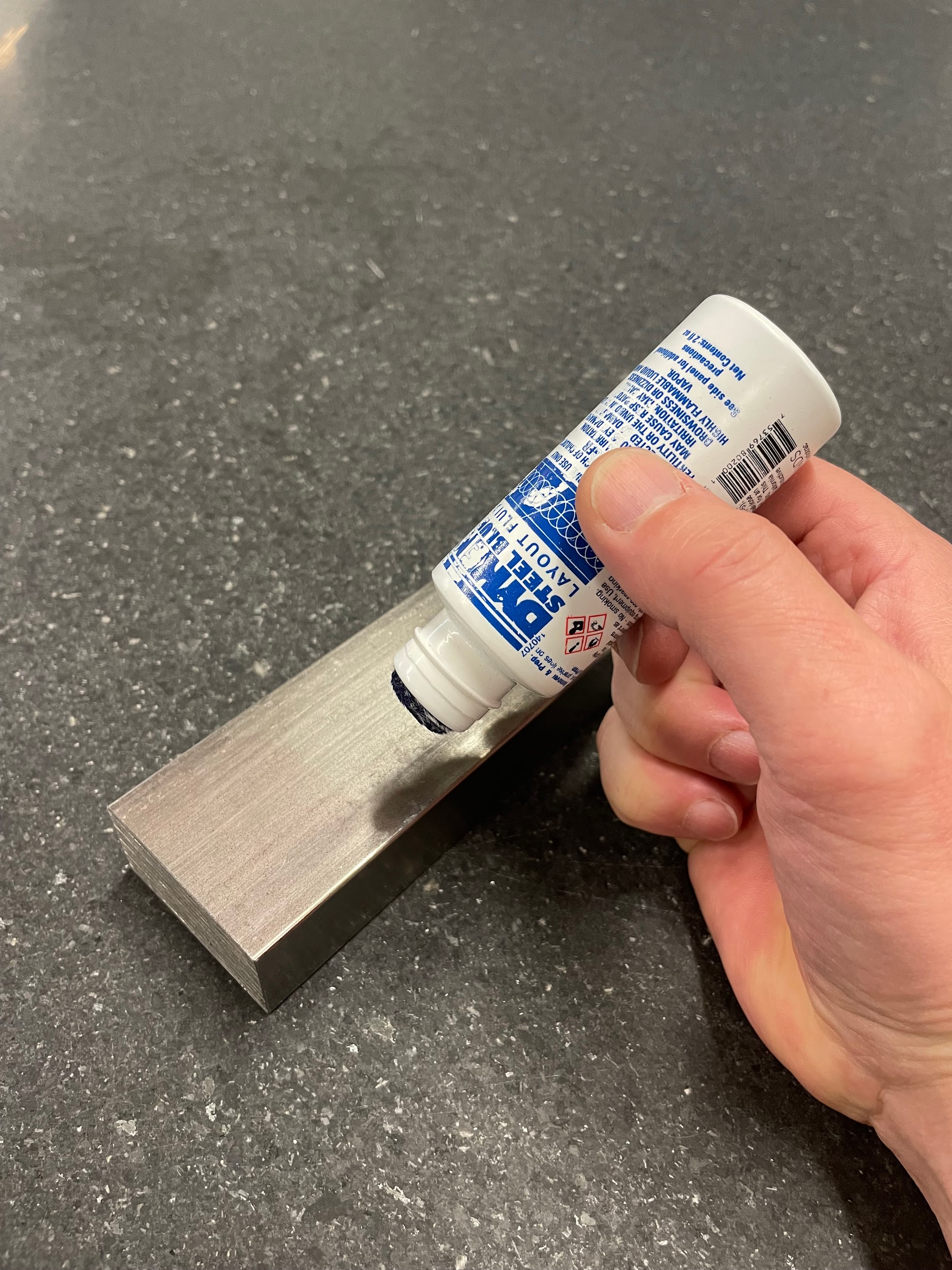
Step 1: Lay out holes to be drilled on material.

Step 1: Lay out holes to be drilled on material.
Step 1: Layout holes to be drilled on material.

Step 1: Lay out holes to be drilled on material.
“Step 1: Layout holes to be drilled on material.”

“Step 1: Layout holes to be drilled on material.”
Step 1: Layout holes to be drilled on material.

Step 2: Center punch hole locations.
Step 3: Clamp part securely in drill vise.
Step 3: Clamp part securely in drill vise.

Step 6: Mount the tool in a drill chuck.

Step 7: Adjust the table height or position.

Step 9: Apply a drop of oil to the center punch mark.

Step 11: If using a center drill, drill down to where the countersink just starts to enter the work. Be careful of the pilot; it is somewhat delicate and can easily be broken off in the part. If using a spot drill, drill down to where the diameter of the tip of the spot drill is slightly larger than the chisel point of the drill.”
Step 11: If using a center drill, drill down to where the countersink just starts to enter the work. Be careful of the pilot; it is somewhat delicate and can easily be broken off in the part. If using a spot drill, drill down to where the diameter of the tip of the spot drill is slightly larger than the chisel point of the drill.”

Step 14: Mount the appropriate twist drill in the drill chuck.

Step 17: Push with light force to initiate the cut. Increase the force until a curling chip is formed by the cutting edge.

Step 22: Examine the drilled hole.
Tolerances
Drilled holes may need to adhere to a specific tolerance callout on the print. Regardless of this tolerance, a quality twist drill should be held to cutting no larger than .005 over the size of the bit itself. If a bit is cutting larger than .005 there are other issues at play and should be investigated further.
Drilling Large Holes and Pilot Drilling
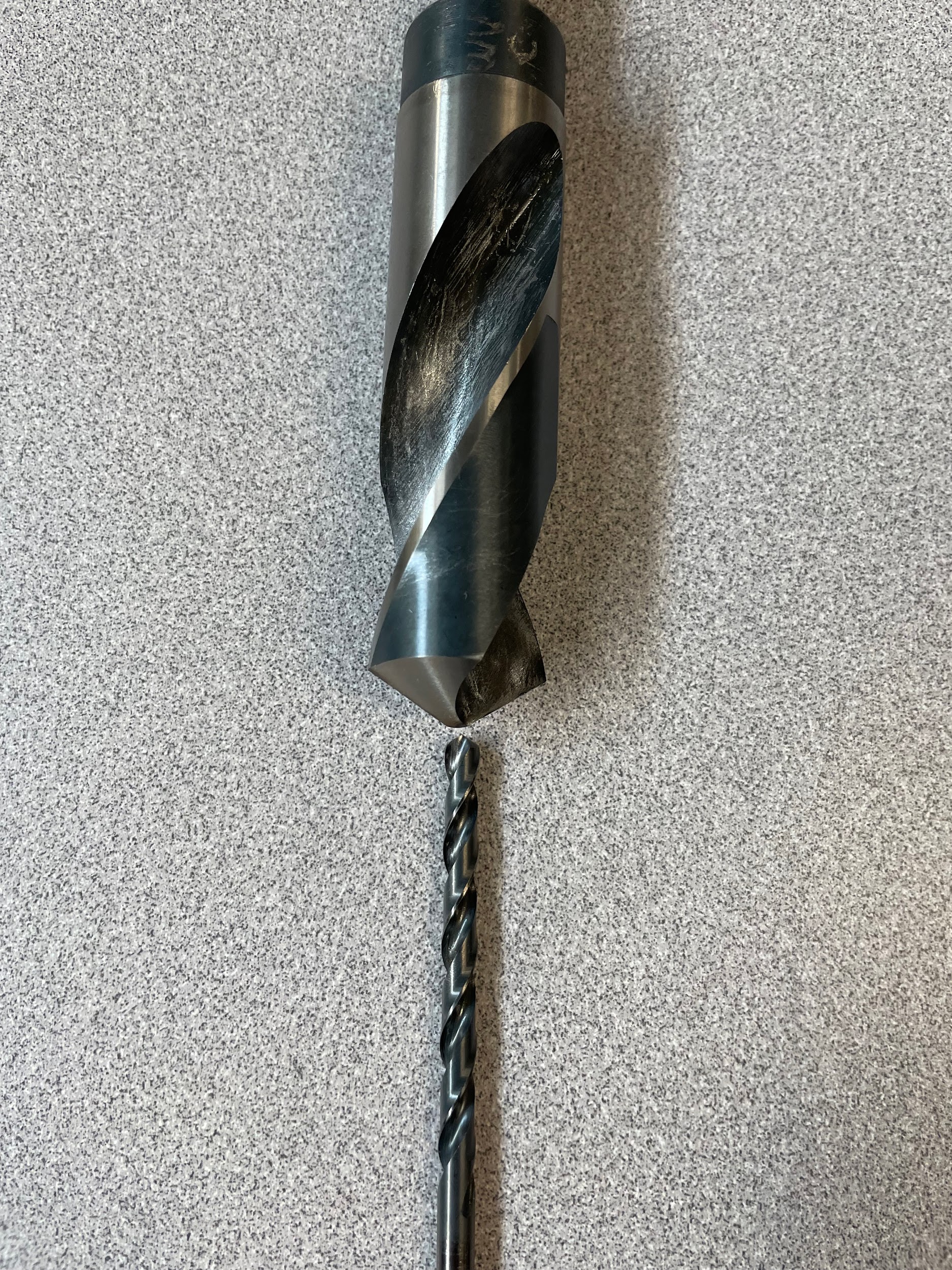
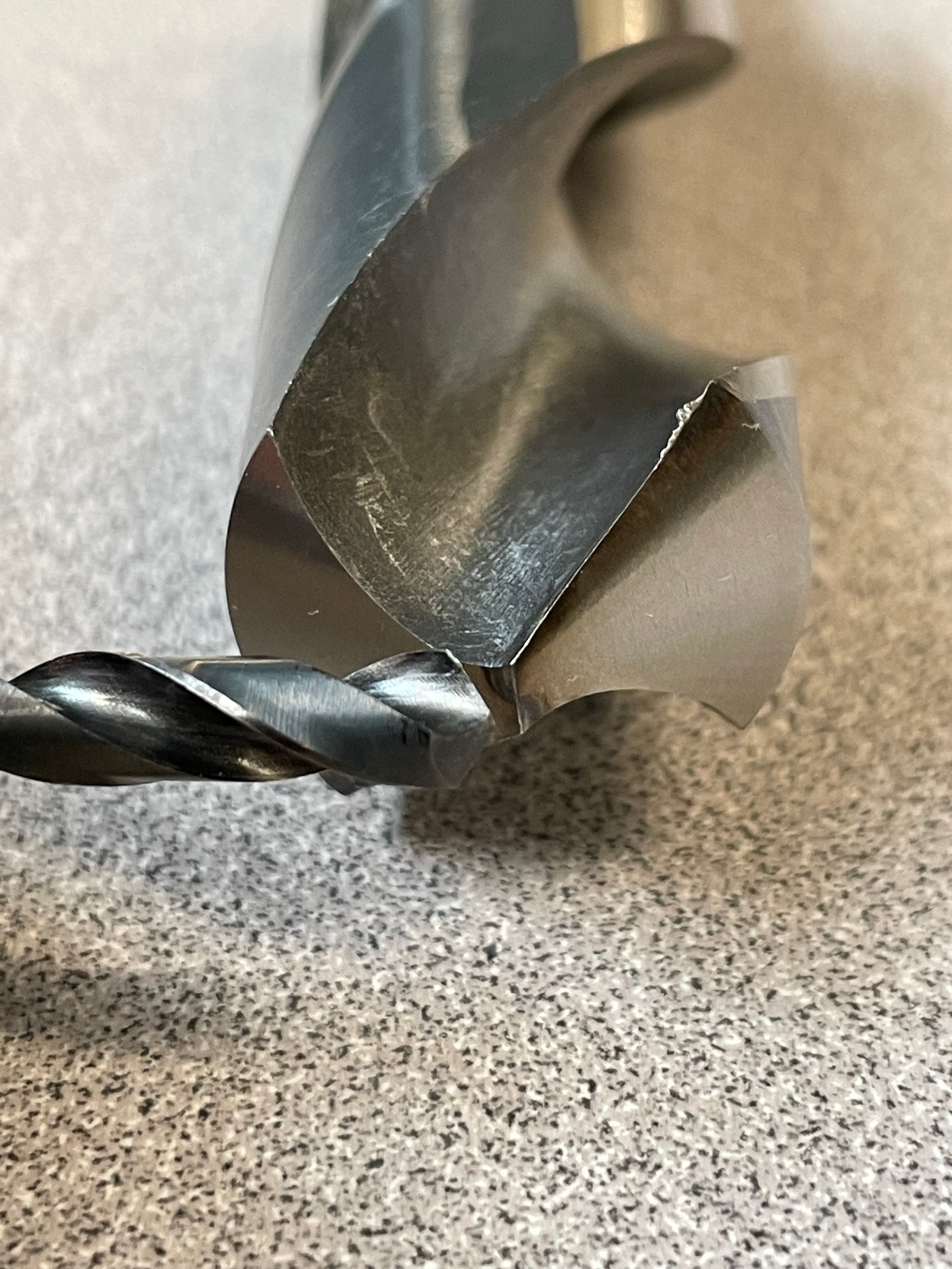
When large holes need to be drilled over ½”, it is sometimes necessary to drill a pilot hole for the larger drill to follow. One reason to use a pilot hole is that the chisel point on large drills can become too long and may produce unwanted heat, friction, and lengthy cut times. Another reason to pilot drill is because the machine used may lack the horsepower required to plunge the entire large bit in one pass. Generally speaking, whenever pilot holes are drilled, they should be only slightly larger than the chisel point of the larger twist drill. If too large of a pilot bit is used, the drill may cut too freely causing chatter because of the lack of tool pressure. Another precaution is stepping up twist drill sizes in small increments. At first, this may seem like the perfect answer. These cuts, however, will put all the work on the very end of the cutting edges, at the margins, overheating or damaging them. If multiple bits are to be used because of horsepower restrictions, it is best to determine the largest bit diameter that a particular machine can handle and use that for calculating the successive bits. This will keep the optimal cutting edge engaged in the work at each step. Below is an example of choosing multiple bit sizes. In this example, the operator needs to drill a 1″ hole, but the drill press at hand only has enough power to drill a 7/16″ hole.
1″ / .4375″ = 2.285
3 drills are needed of equal size.
1″ / 3 drills = .333
The first drill should be somewhere around .333, maybe a fractional size or two larger because the smallest twist drill will be the easiest to turn.
The second drill should be somewhere around .666, again maybe the closest available fractional bit size larger.
The third bit at 1″ will take the most power and should have the least size jump.
In theory, this formula should get an operator close to where each bit is cutting an efficient amount while still allowing a little extra torque at each successive step.
Attributions
- Figure 8.80: Applying layout dye by Micky R. Jennings, courtesy of Wenatchee Valley College, for WA Open ProfTech, © SBCTC, CC BY 4.0
- Video 8.11: Micky R. Jennings, courtesy of Wenatchee Valley College, for WA Open ProfTech, © SBCTC, CC BY 4.0
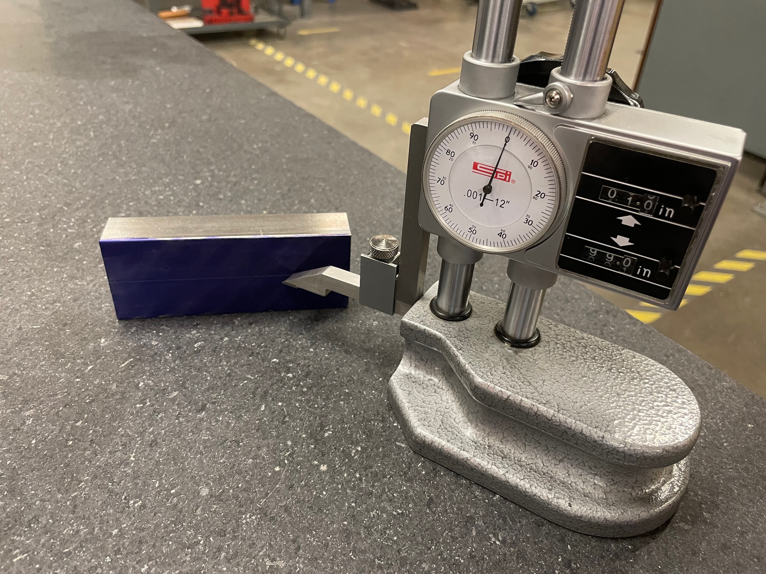
- Figure 8.81: Scribing layout lines with height gage by Micky R. Jennings, courtesy of Wenatchee Valley College, for WA Open ProfTech, © SBCTC, CC BY 4.0
- Video 8.12: Micky R. Jennings, courtesy of Wenatchee Valley College, for WA Open ProfTech, © SBCTC, CC BY 4.0
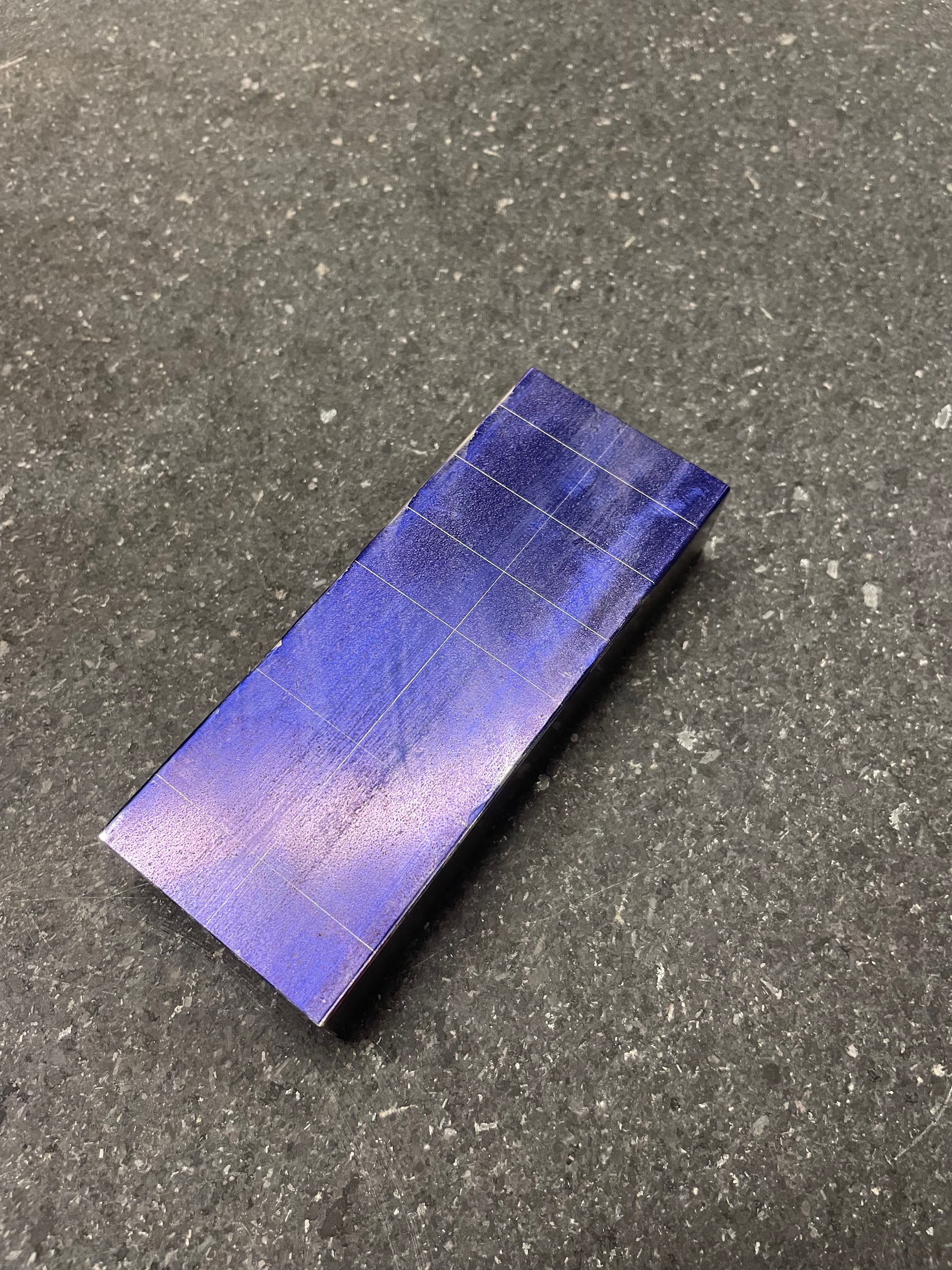
- Figure 8.82: Finished layout lines by Micky R. Jennings, courtesy of Wenatchee Valley College, for WA Open ProfTech, © SBCTC, CC BY 4.0
- Figure 8.83: Prick punching layout intersections by Micky R. Jennings, courtesy of Wenatchee Valley College, for WA Open ProfTech, © SBCTC, CC BY 4.0
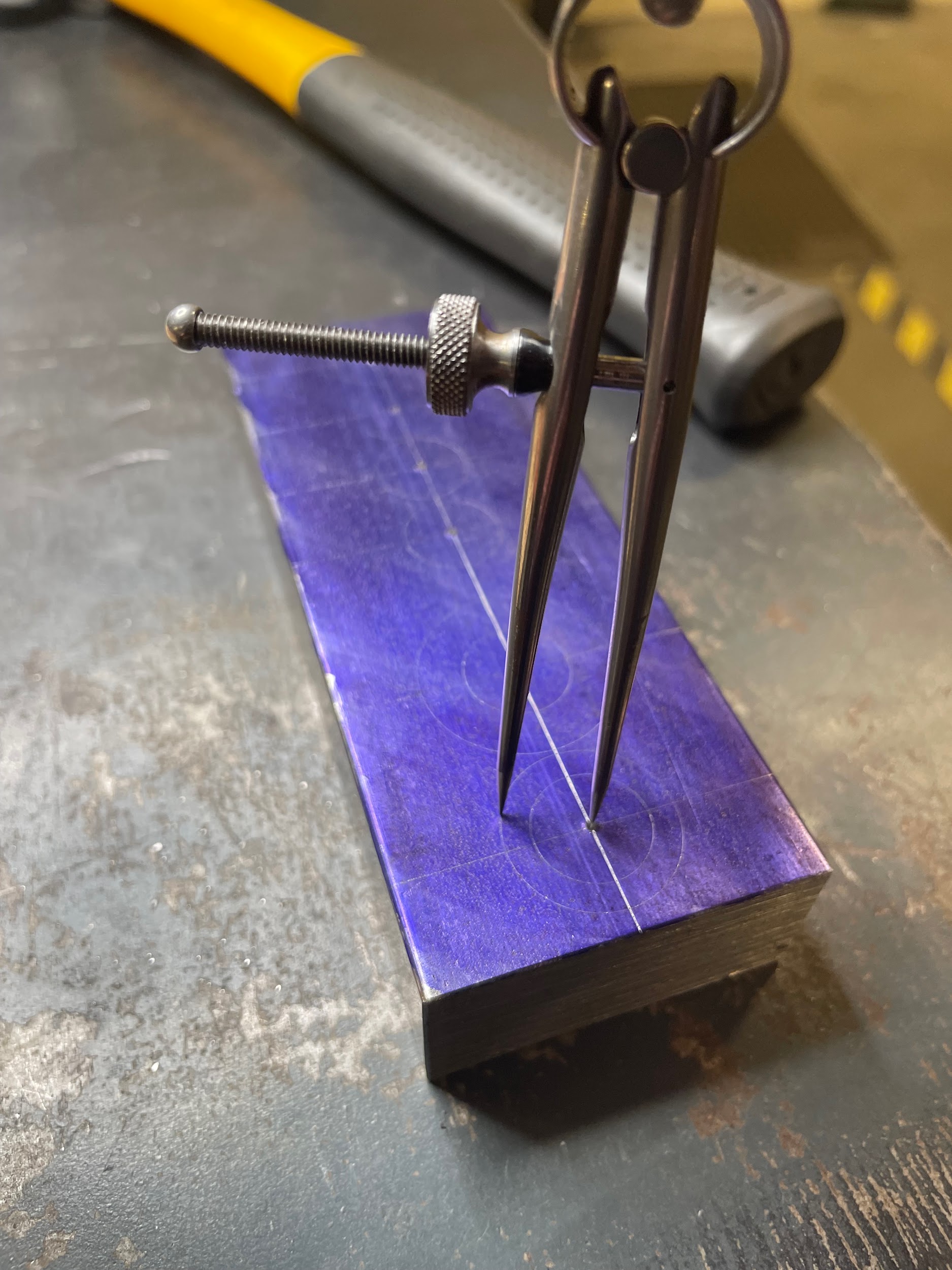
- Figure 8.84: Scribing circles by Micky R. Jennings, courtesy of Wenatchee Valley College, for WA Open ProfTech, © SBCTC, CC BY 4.0
- Video 8.13: Micky R. Jennings, courtesy of Wenatchee Valley College, for WA Open ProfTech, © SBCTC, CC BY 4.0
- Figure 8.85: Center punching holes by Micky R. Jennings, courtesy of Wenatchee Valley College, for WA Open ProfTech, © SBCTC, CC BY 4.0
- Figure 8.86: Part mounted in drill press vise by Micky R. Jennings, courtesy of Wenatchee Valley College, for WA Open ProfTech, © SBCTC, CC BY 4.0
- Video 8.14: Micky R. Jennings, courtesy of Wenatchee Valley College, for WA Open ProfTech, © SBCTC, CC BY 4.0
- Video 8.15: Micky R. Jennings, courtesy of Wenatchee Valley College, for WA Open ProfTech, © SBCTC, CC BY 4.0
- Video 8.16: Micky R. Jennings, courtesy of Wenatchee Valley College, for WA Open ProfTech, © SBCTC, CC BY 4.0
- Video 8.17: Micky R. Jennings, courtesy of Wenatchee Valley College, for WA Open ProfTech, © SBCTC, CC BY 4.0
- Figure 8.87: Spotting holes by Micky R. Jennings, courtesy of Wenatchee Valley College, for WA Open ProfTech, © SBCTC, CC BY 4.0
- Video 8.18: Micky R. Jennings, courtesy of Wenatchee Valley College, for WA Open ProfTech, © SBCTC, CC BY 4.0
- Video 8.19: Micky R. Jennings, courtesy of Wenatchee Valley College, for WA Open ProfTech, © SBCTC, CC BY 4.0
- Video 8.20: Micky R. Jennings, courtesy of Wenatchee Valley College, for WA Open ProfTech, © SBCTC, CC BY 4.0
- Figure 8.88: Hole drilled by Micky R. Jennings, courtesy of Wenatchee Valley College, for WA Open ProfTech, © SBCTC, CC BY 4.0
- Figure 8.89: Pilot drill vs chisel point by Micky R. Jennings, courtesy of Wenatchee Valley College, for WA Open ProfTech, © SBCTC, CC BY 4.0
- Figure 8.90: Pilot drill vs chisel point 2 by Micky R. Jennings, courtesy of Wenatchee Valley College, for WA Open ProfTech, © SBCTC, CC BY 4.0
The process of using a twist drill to create a hole.
