8.14 Counterboring
Micky R. Jennings
Counterboring is the secondary machining process of creating a cylindrical shape at the top of a hole using a counterbore. Counterbored holes are often used to recess socket head cap screws below the surface of a part.
Prior allowances
Before counterboring on a drill press, a hole is required. The size of that hole is often given on a print with the allowance built in. General fastener clearance is 1/64 to 1/32 of an inch. The pilot at the end of standard counterbores is going to be 1/64 to 1/32 larger than the nominal size of the bolt for that reason.
Step by step process for counterboring:
- Drill all hole locations with appropriate sized twist drill.
- Select a counterbore and insert it into the drill chuck.
- Calculate the spindle speed of the counterbore by using the largest diameter the tool will touch the material. If the operator is unsure of this size, the top of a fastener can be measured for reference. Calculate the speed based on a twist drill of that large diameter, and then use the counterboring speed reduction, 1/4 of the speed for counterboring, to set the final speed.
- Calculate the depth of the counterbore. The print is often a good indicator of counterbore depth. If depth isn’t indicated on the print, a manufacturing reference book will have general depth information.
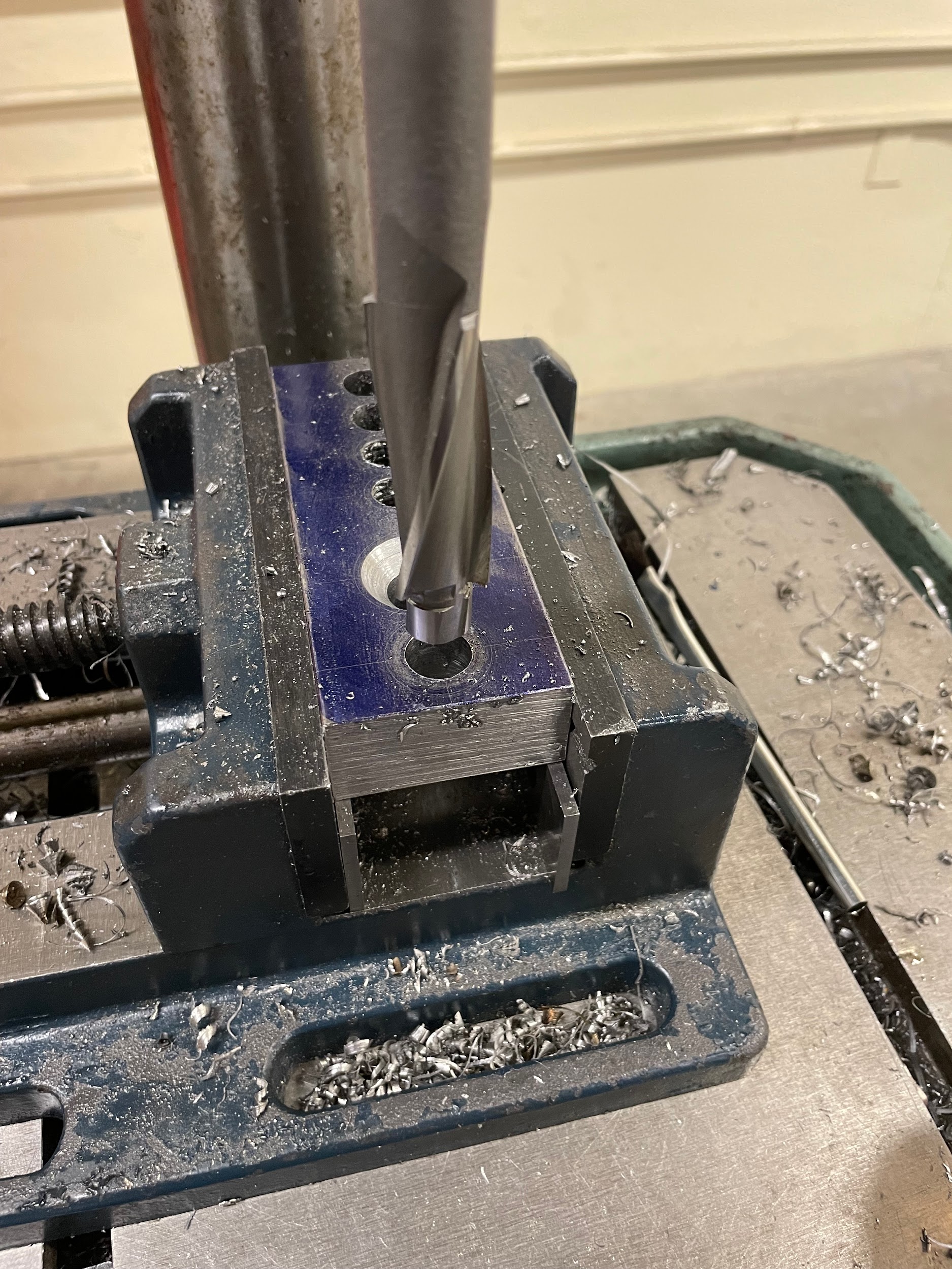
- Bring the quill down slowly, positioning the counterbore to touch fully at the top of the hole.
- Set the depth stop of the drill press quill movement.
- Raise the quill.
- Apply cutting oil to the counterbore flutes and to the top of the material, allowing them to slide down the sides of the hole.
- Start the spindle.
- Hold the drill vise firmly and pull the quill handle to enter the hole and cut the counterbore. This may require small pecking to break chips.
- Examine the counterbored hole.
Step 2: Select a counterbore and insert it into the drill chuck.
Step 8: Apply cutting oil to the counterbore flutes and to the top of the material, allowing them to slide down the sides of the hole.

Step 10: Hold the drill vise firmly and pull the quill handle to enter the hole and cut the counterbore. This may require small pecking to break chips.

Step 11: Examine the counterbored hole.

Tolerances
Counterboring tolerance for general fasteners are usually just clearance, meaning the depth and the diameter might not be critical, and can use standard tolerances found in manufacturing reference books. However, sometimes a counterbore is for more than general fastener use, and will require tighter tolerance. In these cases, the print will reflect this and give the proper tolerance.
Attributions
- Figure 8.97: Counterbore positioned above hole by Micky R. Jennings, courtesy of Wenatchee Valley College, for WA Open ProfTech, © SBCTC, CC BY 4.0
- Video 8.33: Micky R. Jennings, courtesy of Wenatchee Valley College, for WA Open ProfTech, © SBCTC, CC BY 4.0
- Video 8.34: Micky R. Jennings, courtesy of Wenatchee Valley College, for WA Open ProfTech, © SBCTC, CC BY 4.0
- Video 8.35: Micky R. Jennings, courtesy of Wenatchee Valley College, for WA Open ProfTech, © SBCTC, CC BY 4.0
The process of making a counterbore. See counterbore
