9.7 Tooling
Micky R. Jennings
Tooling is a term used to talk about the tools used on machinery to cut the parts. On milling machines, the tooling might look similar to that of a drill press; however, aside from hole making tooling, the tooling designed for a milling machine is very different. Specifically, milling machine tooling is designed to cut horizontally. Because of the capability of the milling machine to facilitate sideways cutting, the machinist can create flat, straight sides and rectangular parts. The tooling for a milling machine consists of a variety of different designs that allow the machinist to create different shapes for the features that may be required of a part.
Tooling Materials
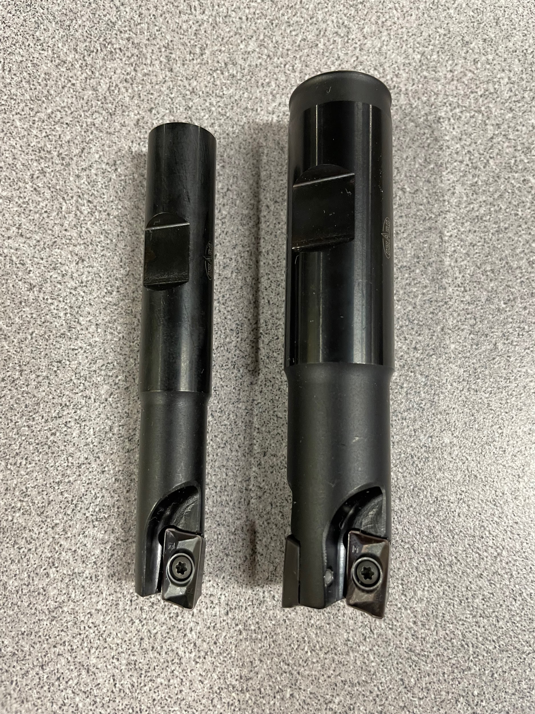
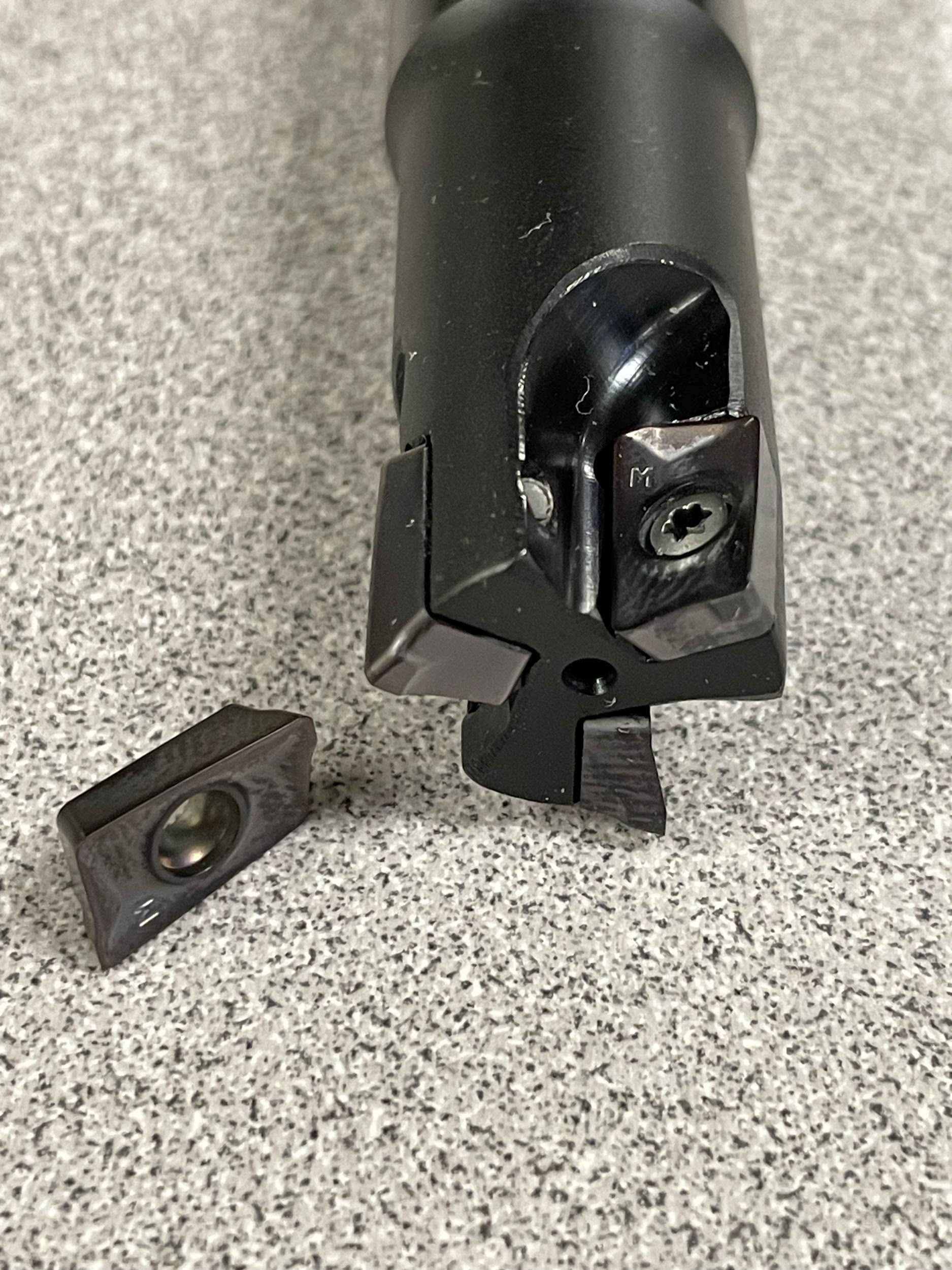
Tooling for milling machines can be made of several different materials. High speed steel (HSS) is often considered the baseline material for tooling in a machine shop and is typically used on manual milling machines because it is an economical material for end mills and other rotary tooling. Generally, machine tools for cutting metal will never be of a quality less than HSS; however, there are many materials that have properties greater than HSS that are occasionally used on manual milling machines (Beaumont, n.d.). Cobalt tooling has a higher percentage of cobalt in its alloy than regular HSS. It can be used effectively to machine harder alloy steels and stainless steel. Carbide is another very popular tool material for its additional rigidity and heat resistance. In addition to base materials, coatings on tooling are a huge part of selecting a tool. Some tools are also made with an alloy steel body and indexable insert cutting edges. This design makes these tools more economical than a solid carbide tool.
Face Mill
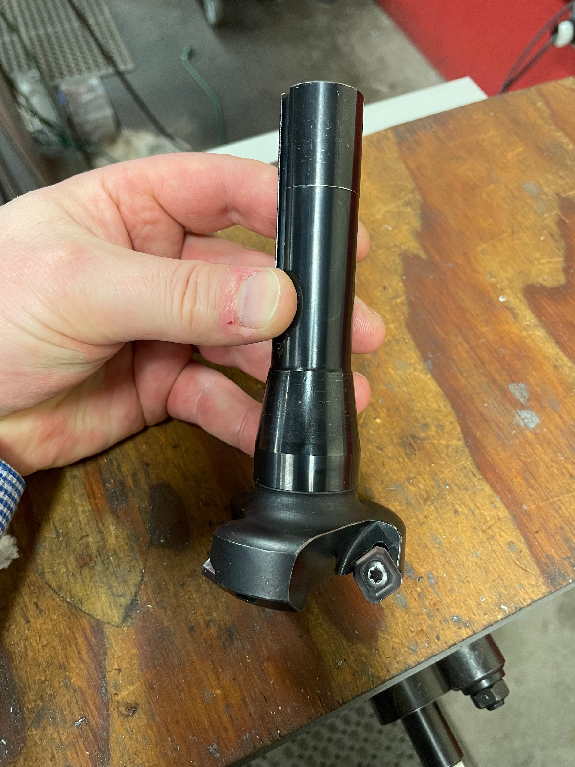
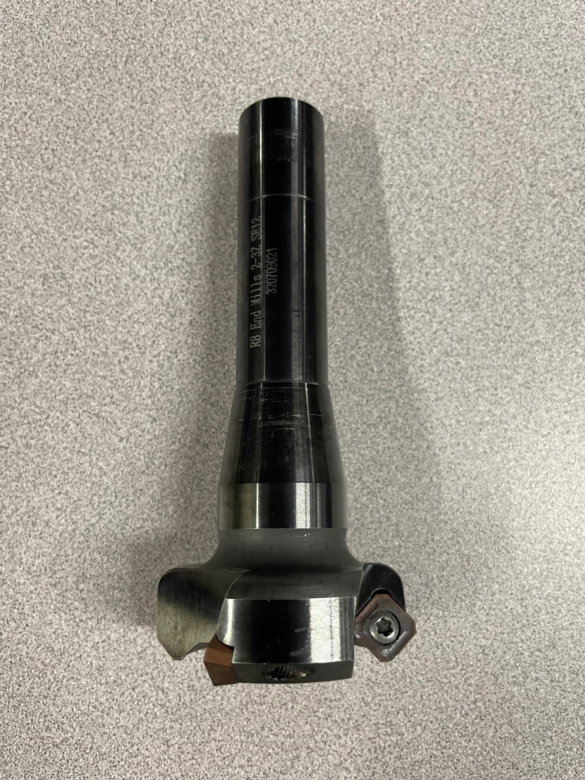
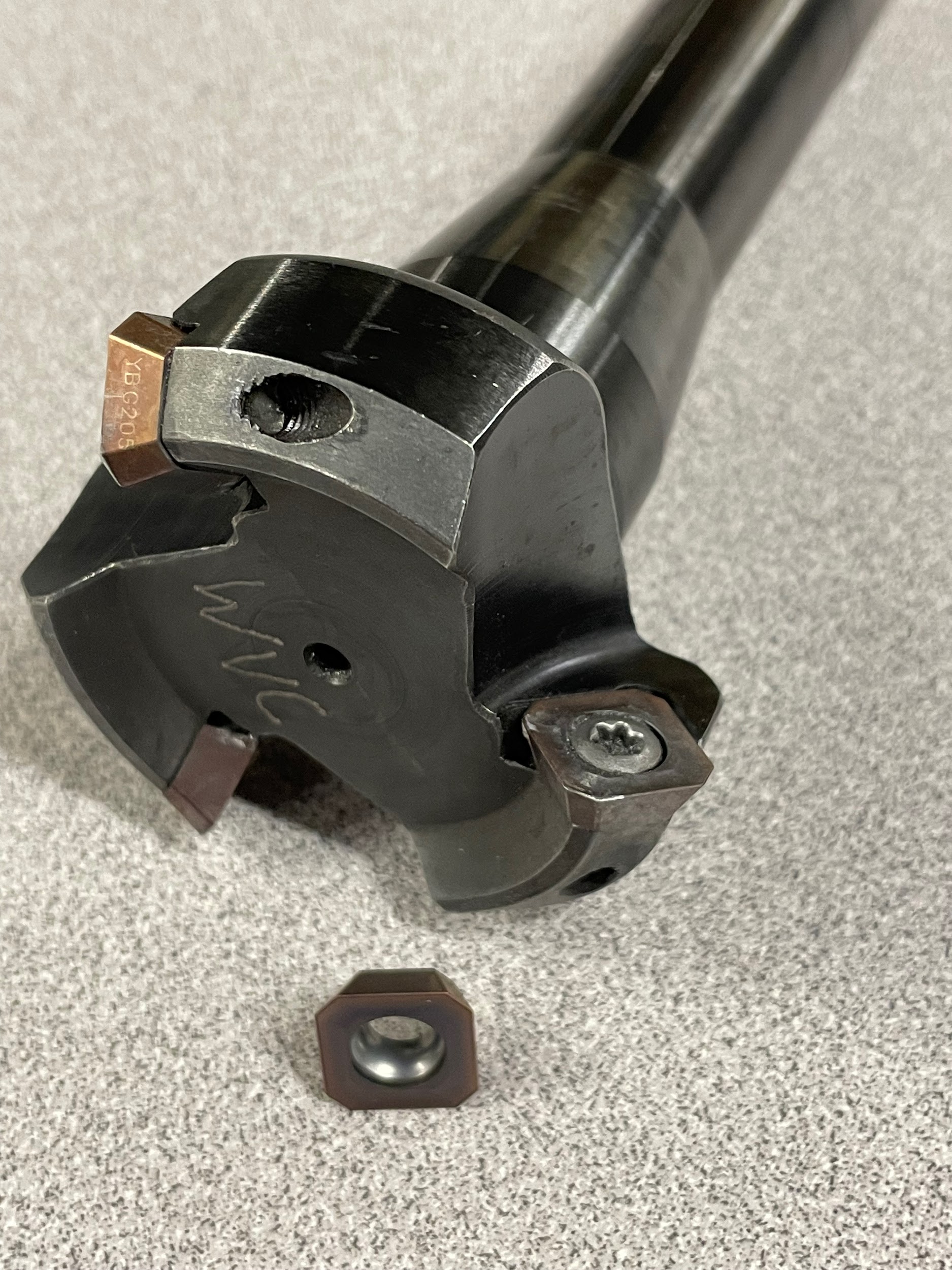
A modern day face mill has many indexable carbide inserts that are designed to cut the top of the work. This cutting action is called facing. Face mills can be as small as 1″ in diameter or as big as 10″or larger. For manual equipment, 1″- 3″ face mills will be the most common. It is advised to use face mills with a high positive rake because of the relatively low horsepower of many vertical manual milling machines. Neutral or negative rake face mills or face mills over 3″ are only recommended for use on larger, more powerful machines. For facing cuts over 3″ in diameter, a fly cutter would be a better tool than a face mill.
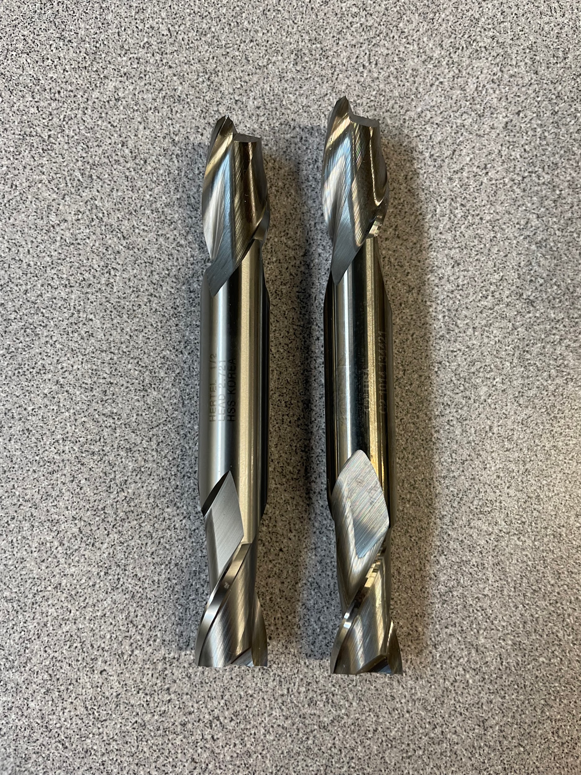
End Mill
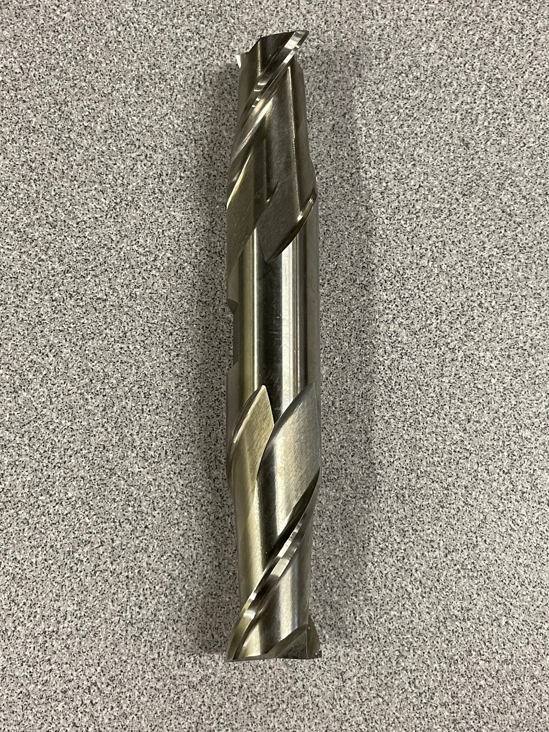
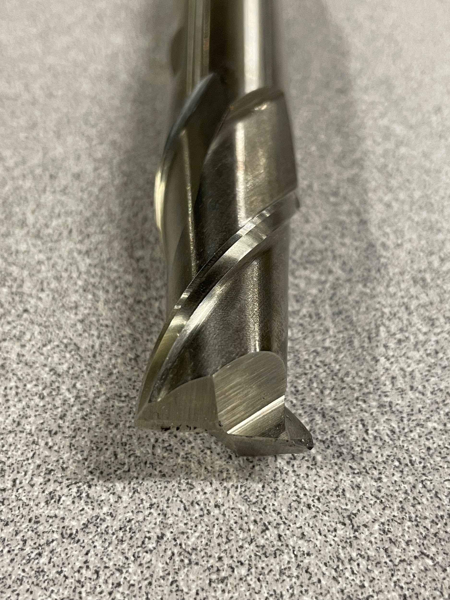
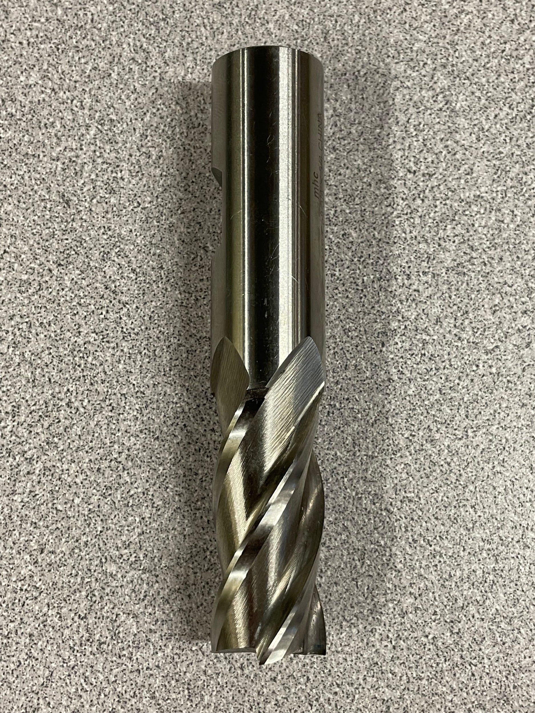
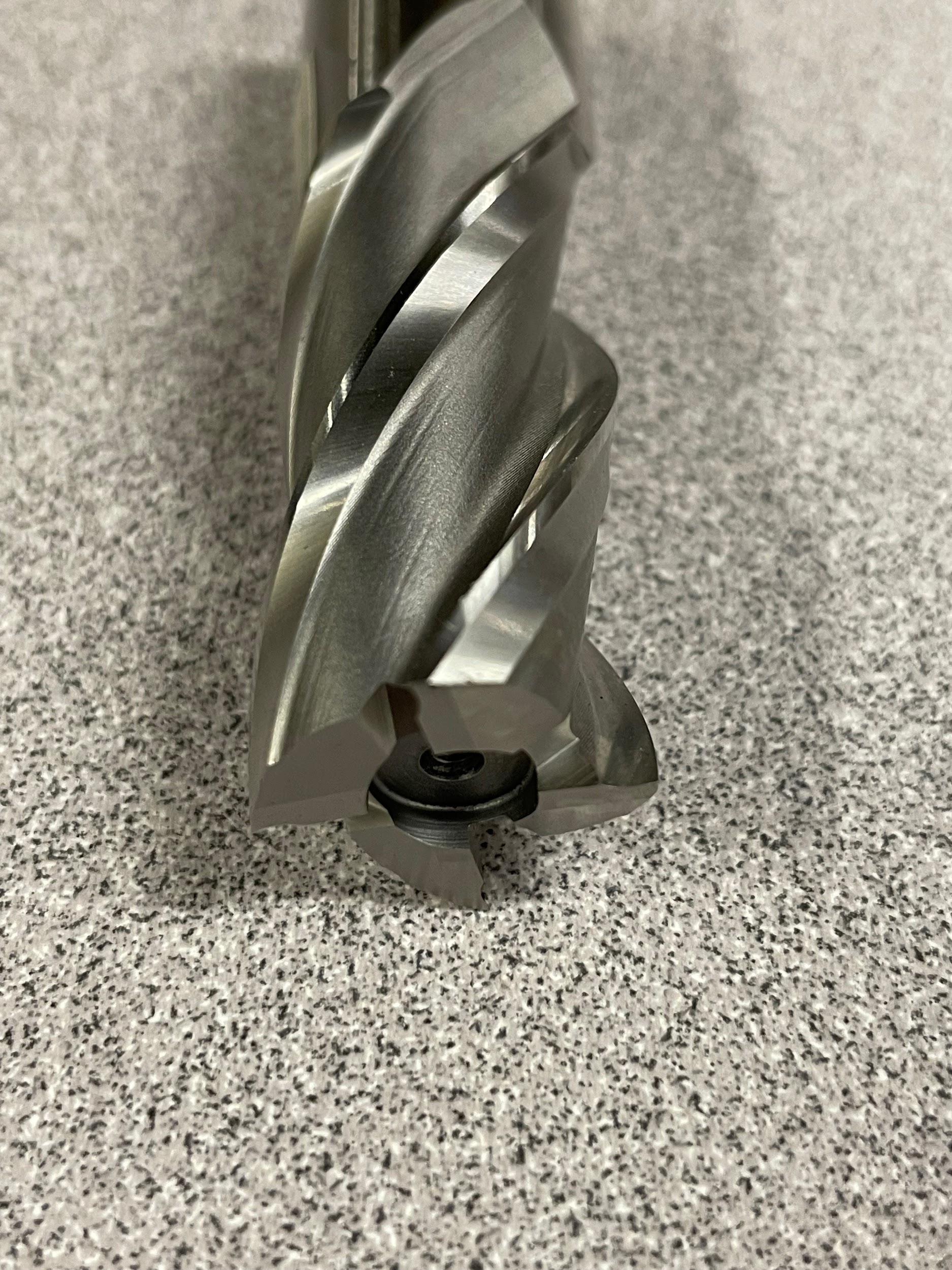
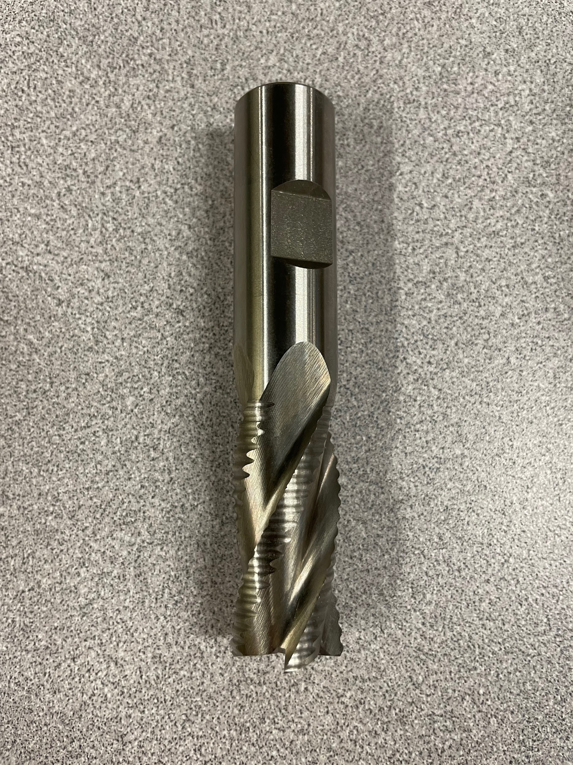
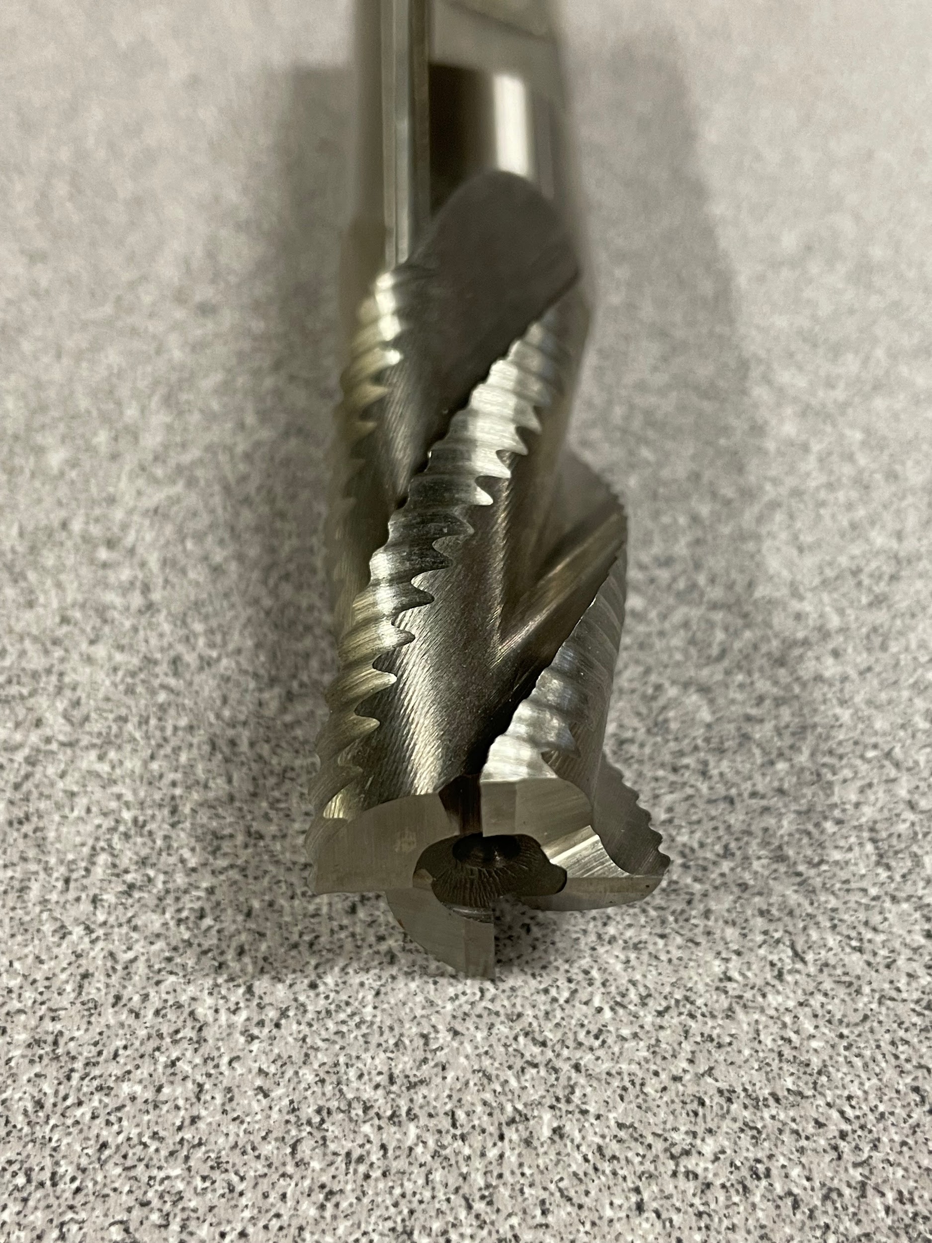
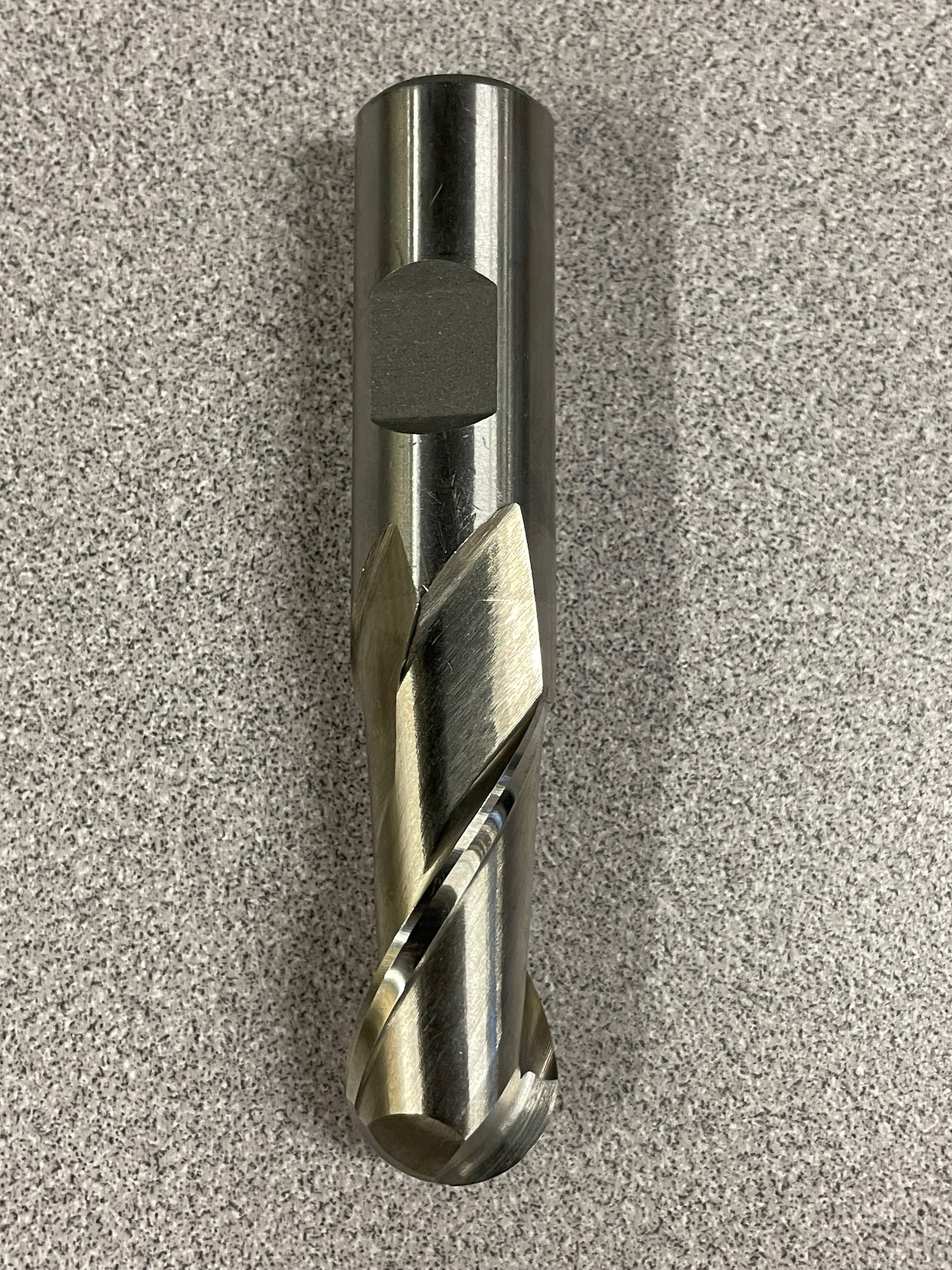
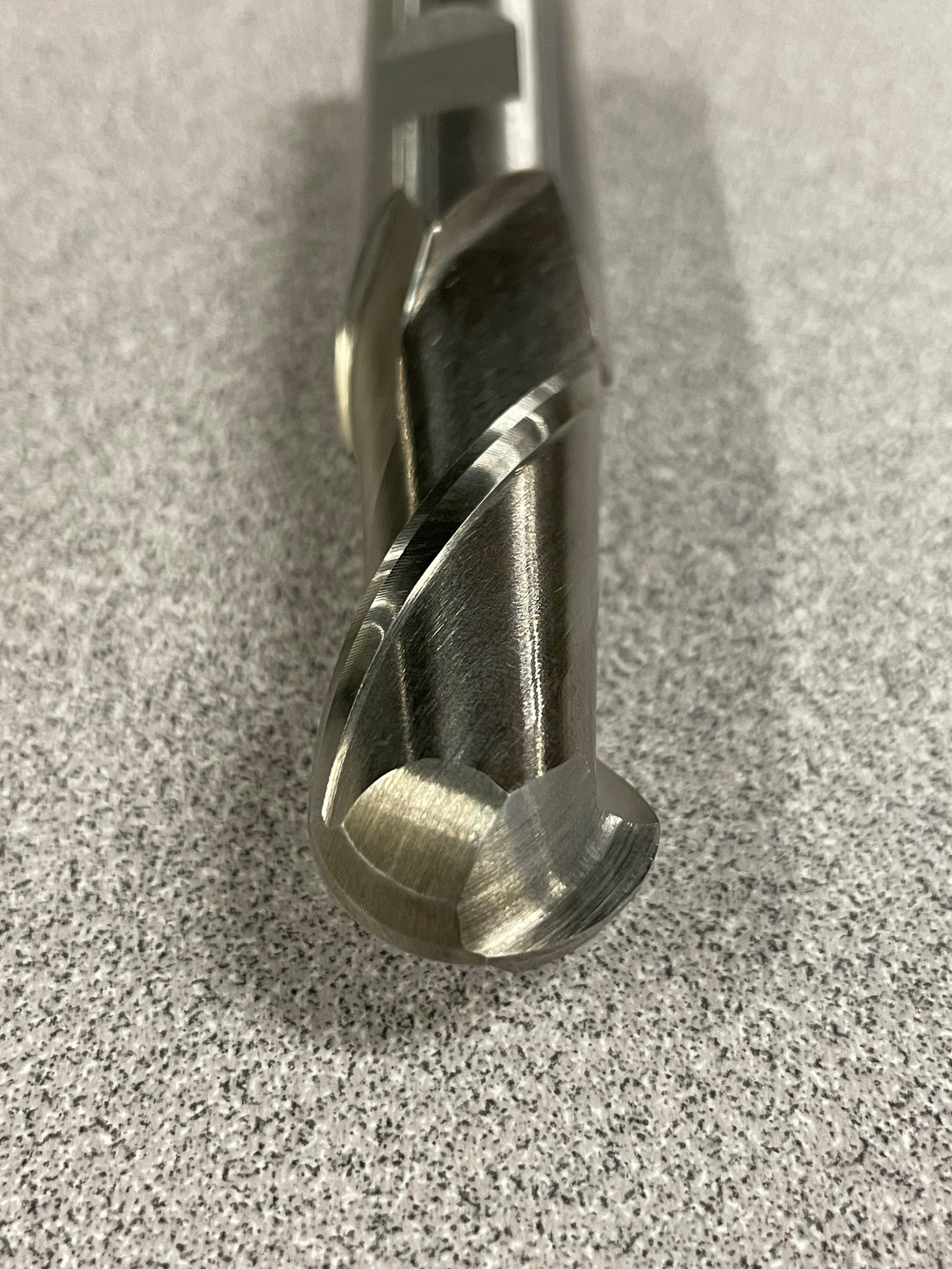
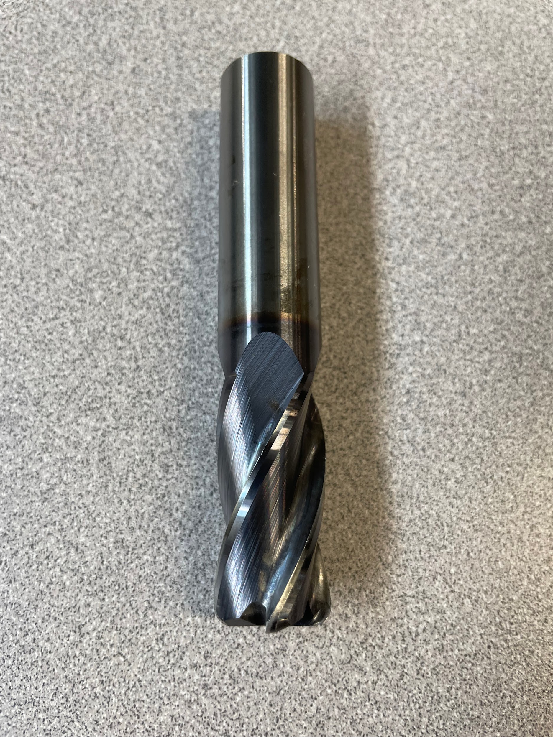
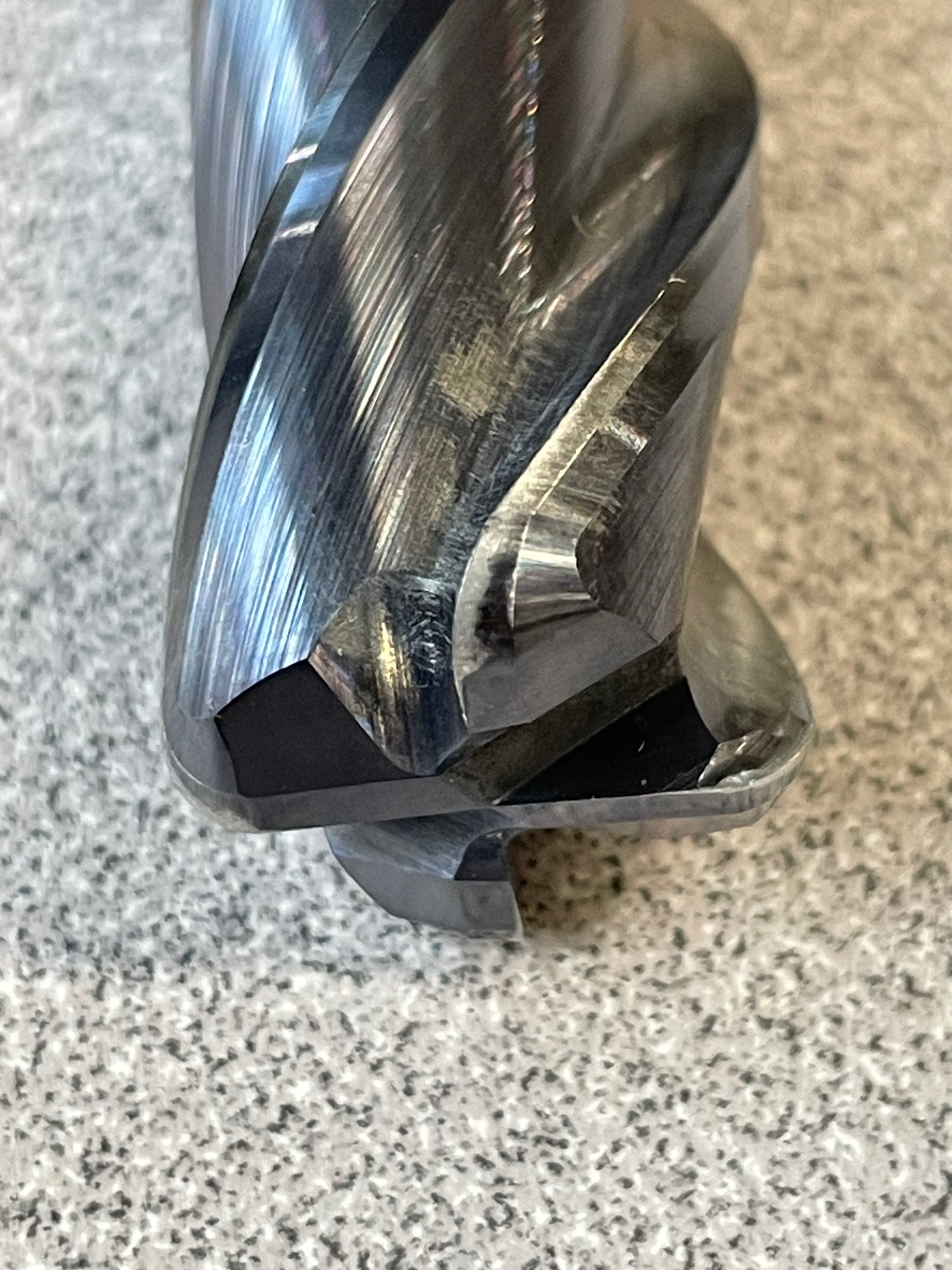
An end mill, despite its name, does a majority of the cutting on the side of the tool. At first glance, the end mill looks similar to the twist drill, but that is where the similarities end. Some end mills are referred to as “center cutting” and are capable of plunge milling with the end of the tool, but this isn’t the tool’s main function. On a milling machine, end mills do a majority of the shaping of parts. From contours and angles to slots, grooves, and bosses, end mills are a very versatile tool. End mills come in a few different styles, rougher, finishing, inserted, ball nose, bull nose, 2- flutes to 6- flutes or more. Generally speaking, for a heavier cutting operation or sticky material, an end mill with fewer flutes works best because it allows the chips to flow freely through the flutes and not build up. For a finishing operation, or in harder materials, an end mill with more flutes can be used because it will remove less material and require less chip clearance. For manual milling machines, ⅛” to ¾” end mills are common. Anything over ¾” is not recommended because it often requires more power and rigidity.
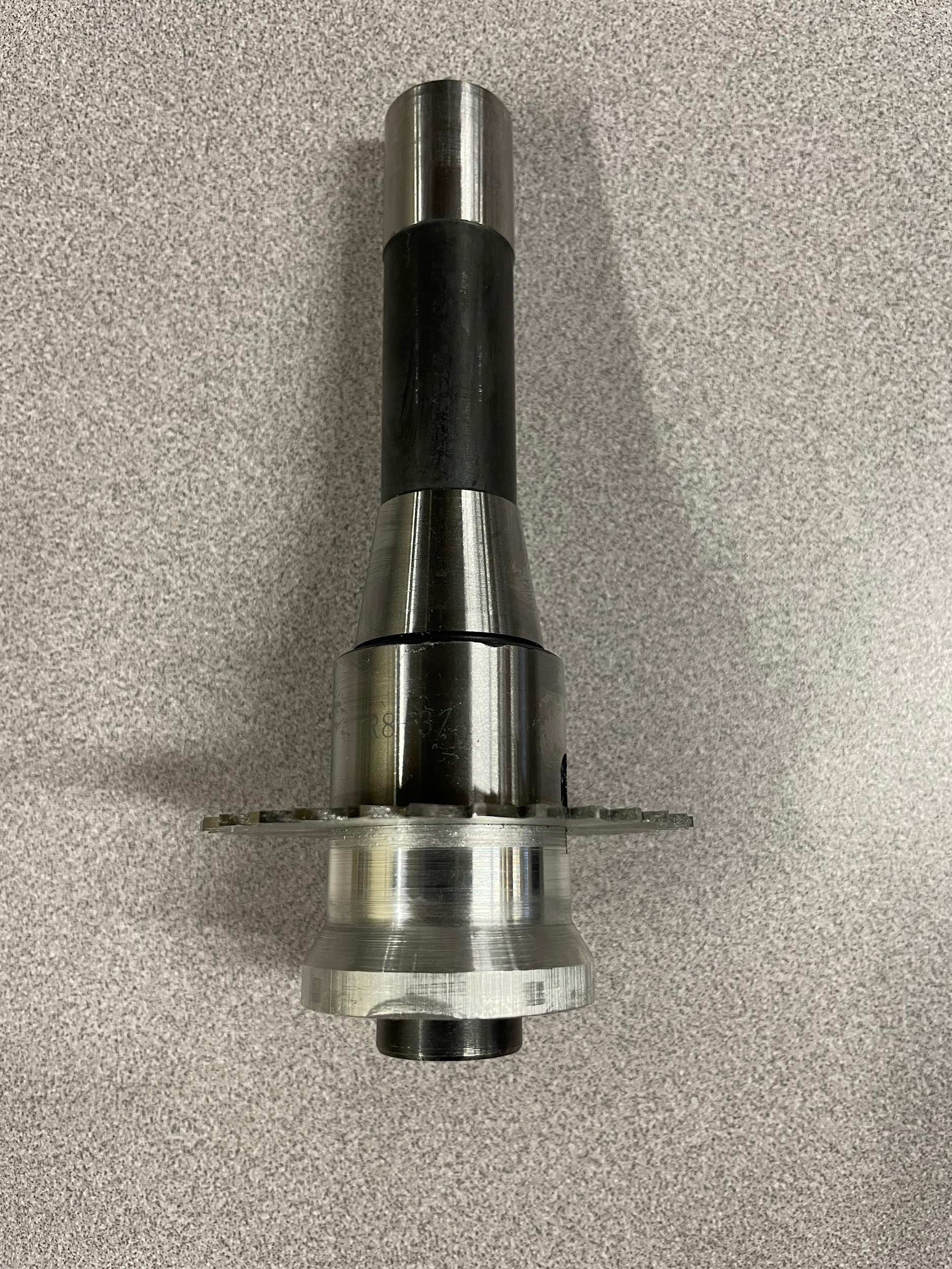
Boring Head
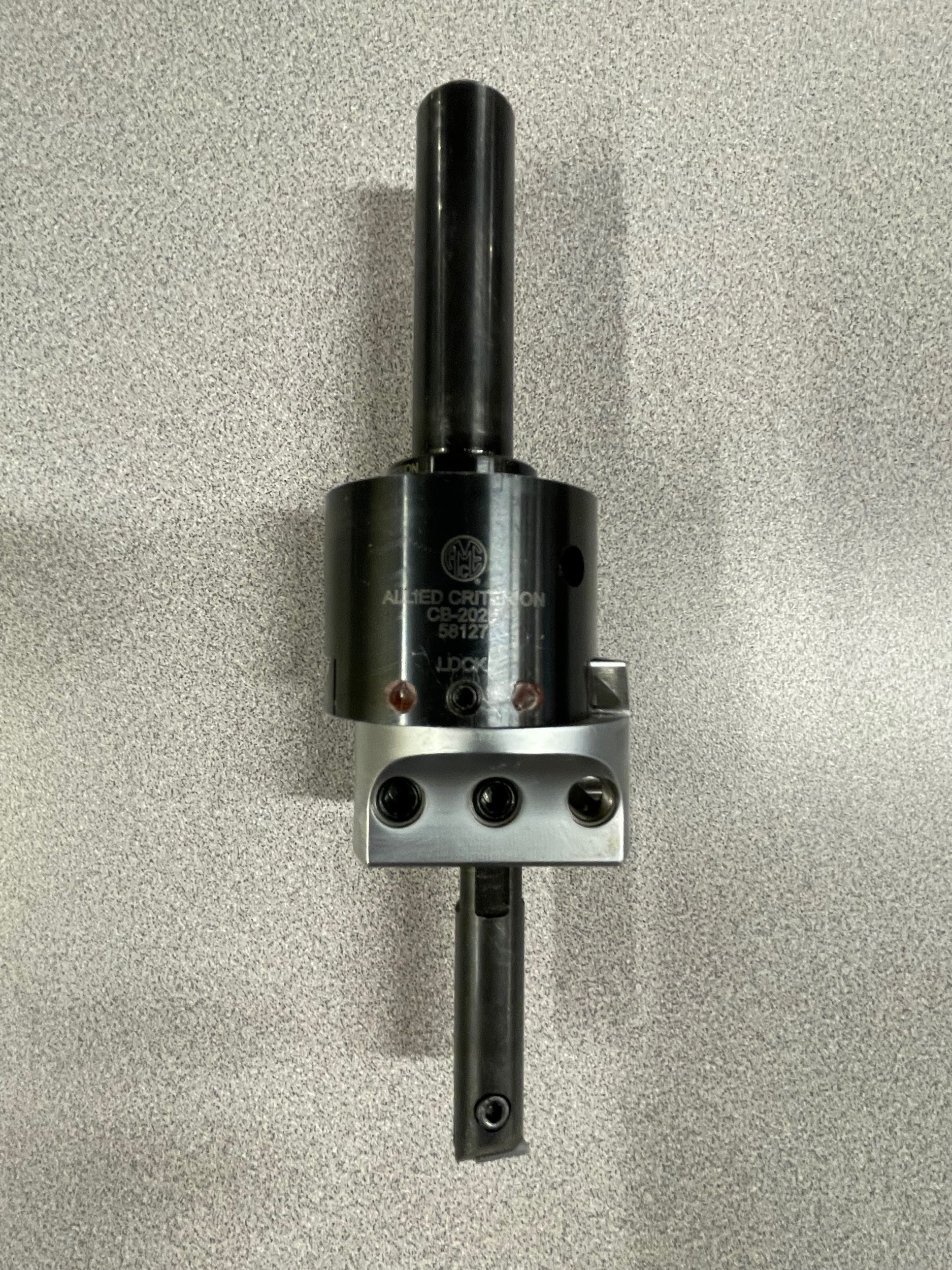
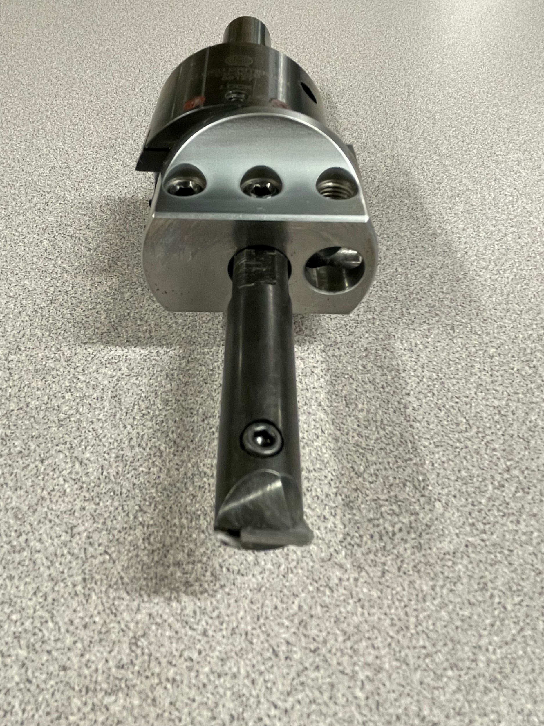
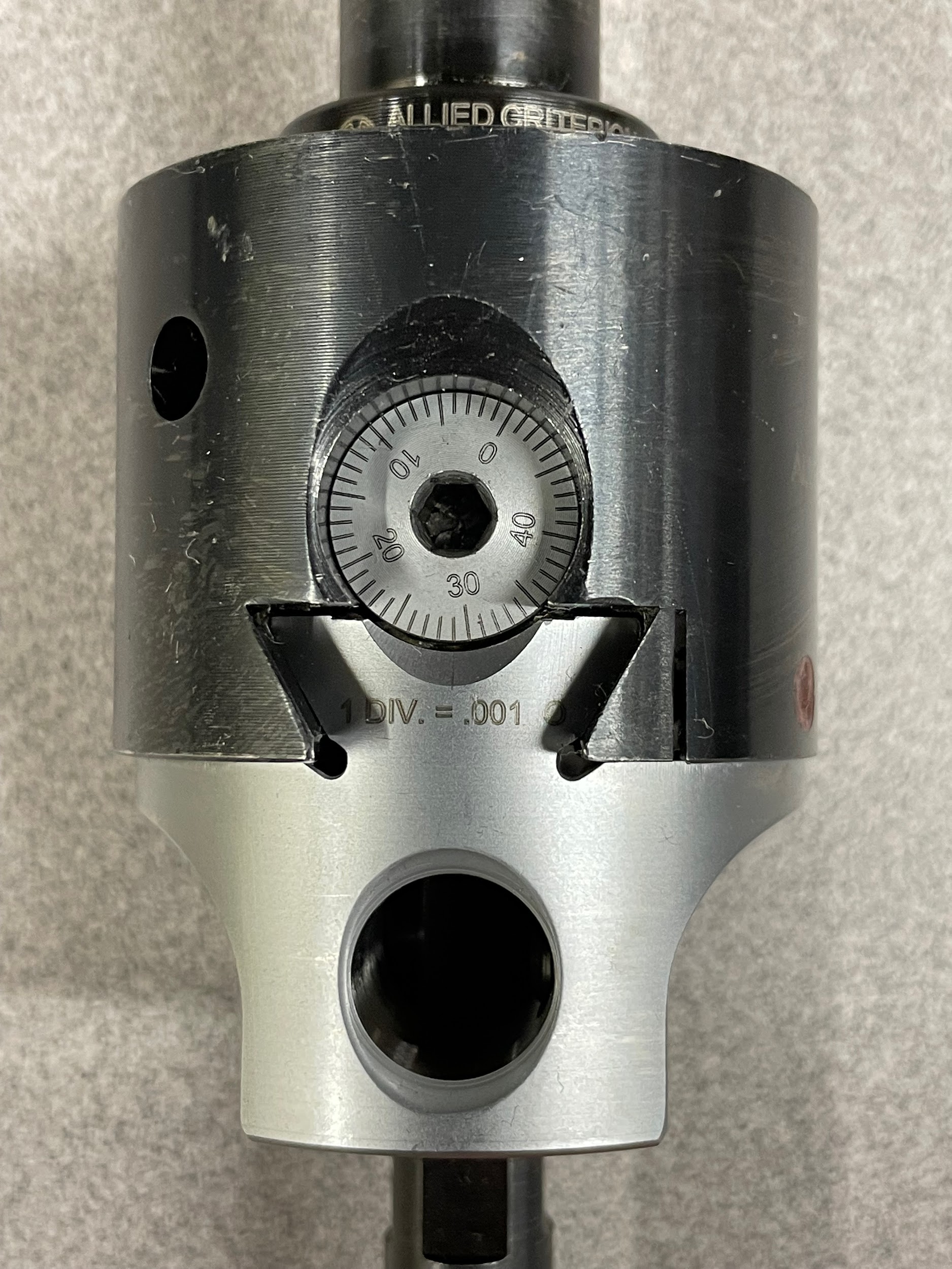
A boring head is a tool used on a milling machine for the purpose of boring holes to size with an attached boring bar. The boring head operates by spinning the offset boring bar in a circle around the center of the spindle. The bottom half of the boring head can accommodate the boring bar in three different positions, two facing down and one facing out. From these three different positions, the boring head is capable of boring a wide range of sizes. The boring head is adjusted by a screw mechanism in the main body, and the lower half moves on a dovetail. This screw mechanism has graduations of .001″. Boring heads come in many different sizes, with, 2″ being a common size for a manual milling machine.
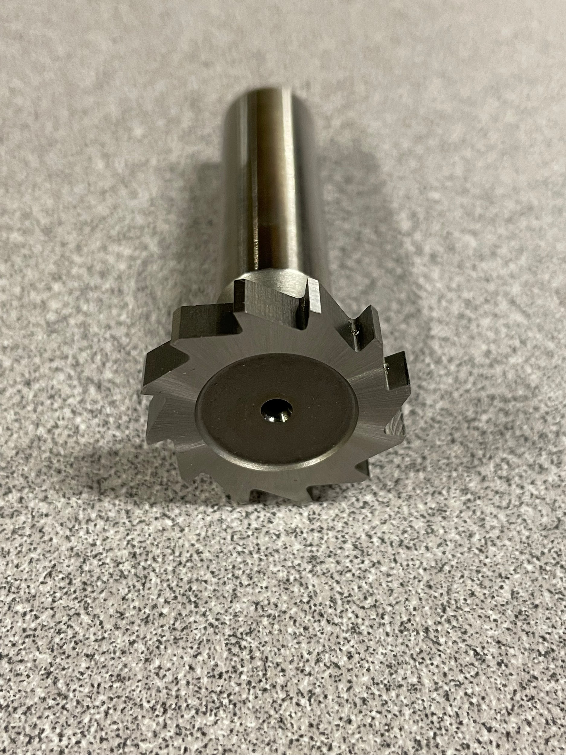
Slitting Saw
A slitting saw is a tool that is used to cut thin sections of material from a part using a horizontally rotating saw blade. The blade is held on an arbor and is secured by a key and a compression cap. Smaller saws may just utilize the clamping force of the cap to hold the saw in place. Slitting saw blades can be HSS, carbide, or carbide inserted to another material. On manual equipment, generally HSS saws under 6″ in diameter are used.
Form Tool
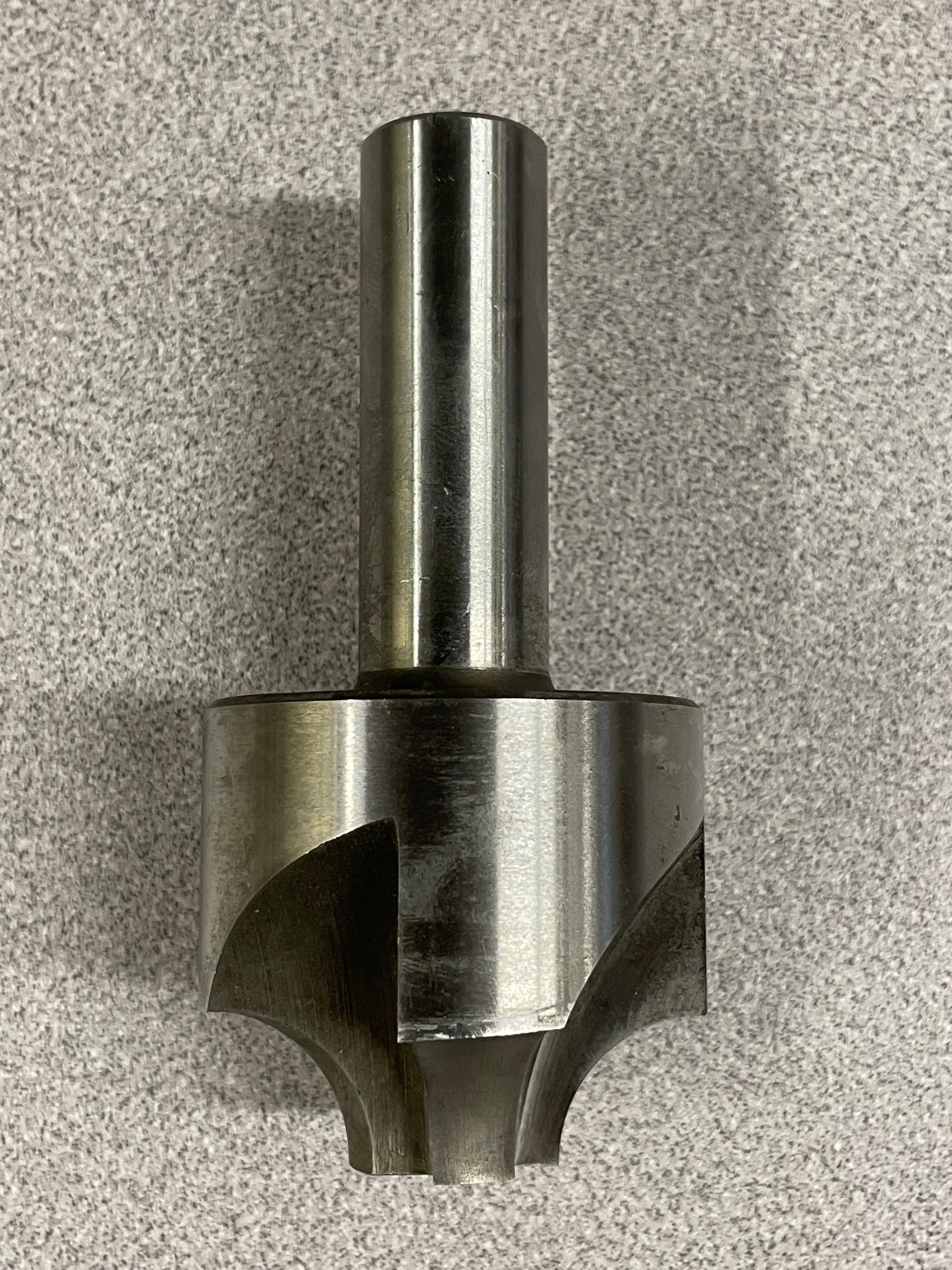
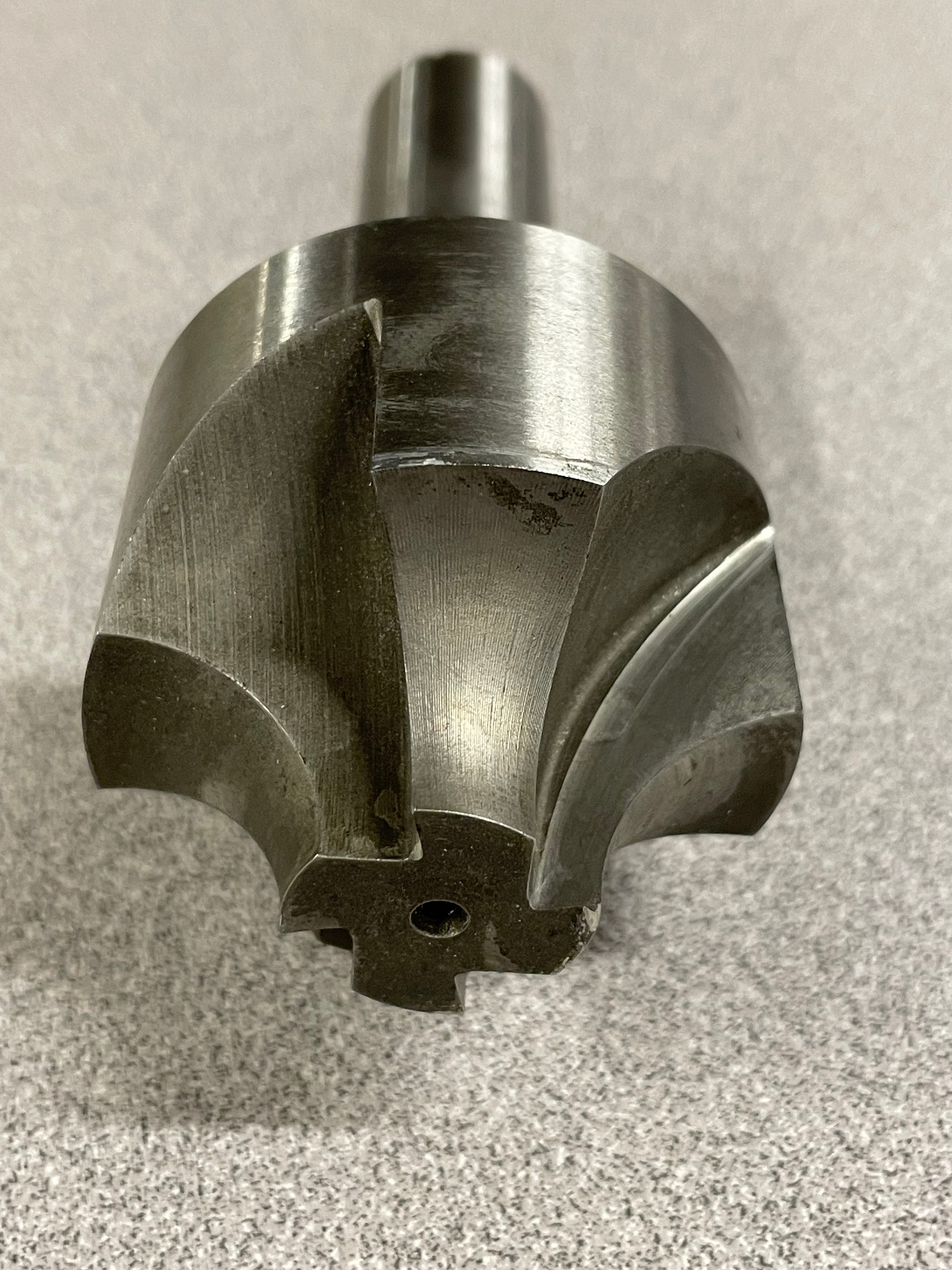
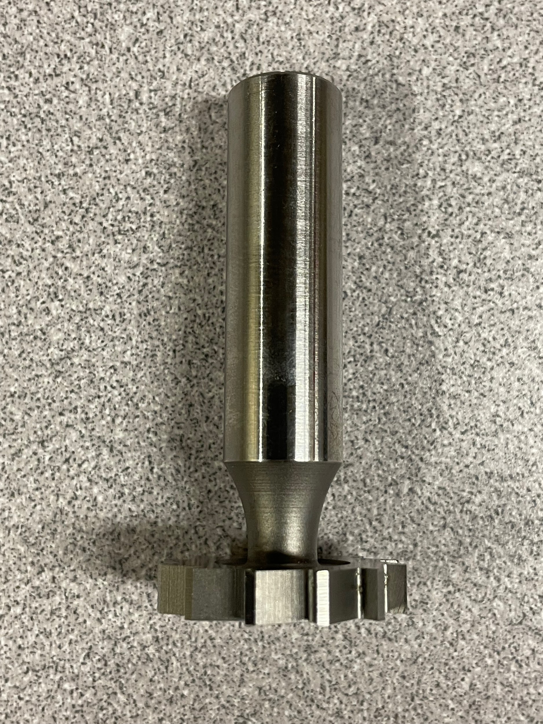
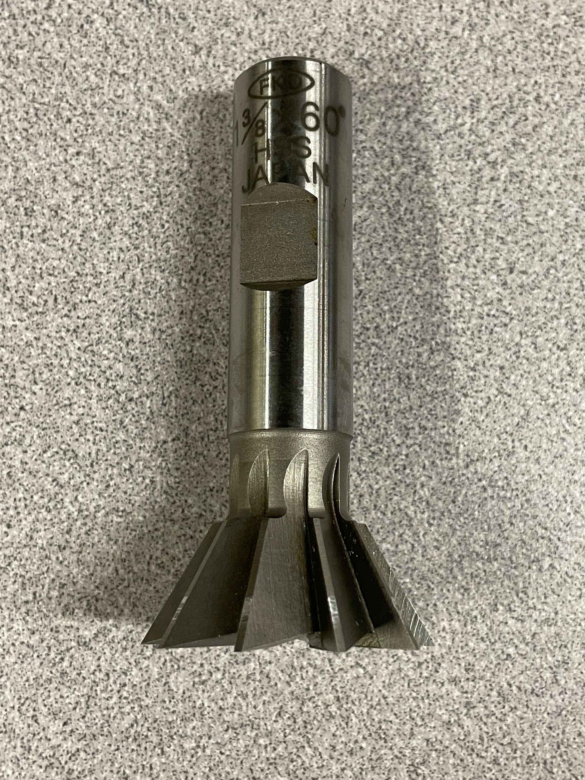
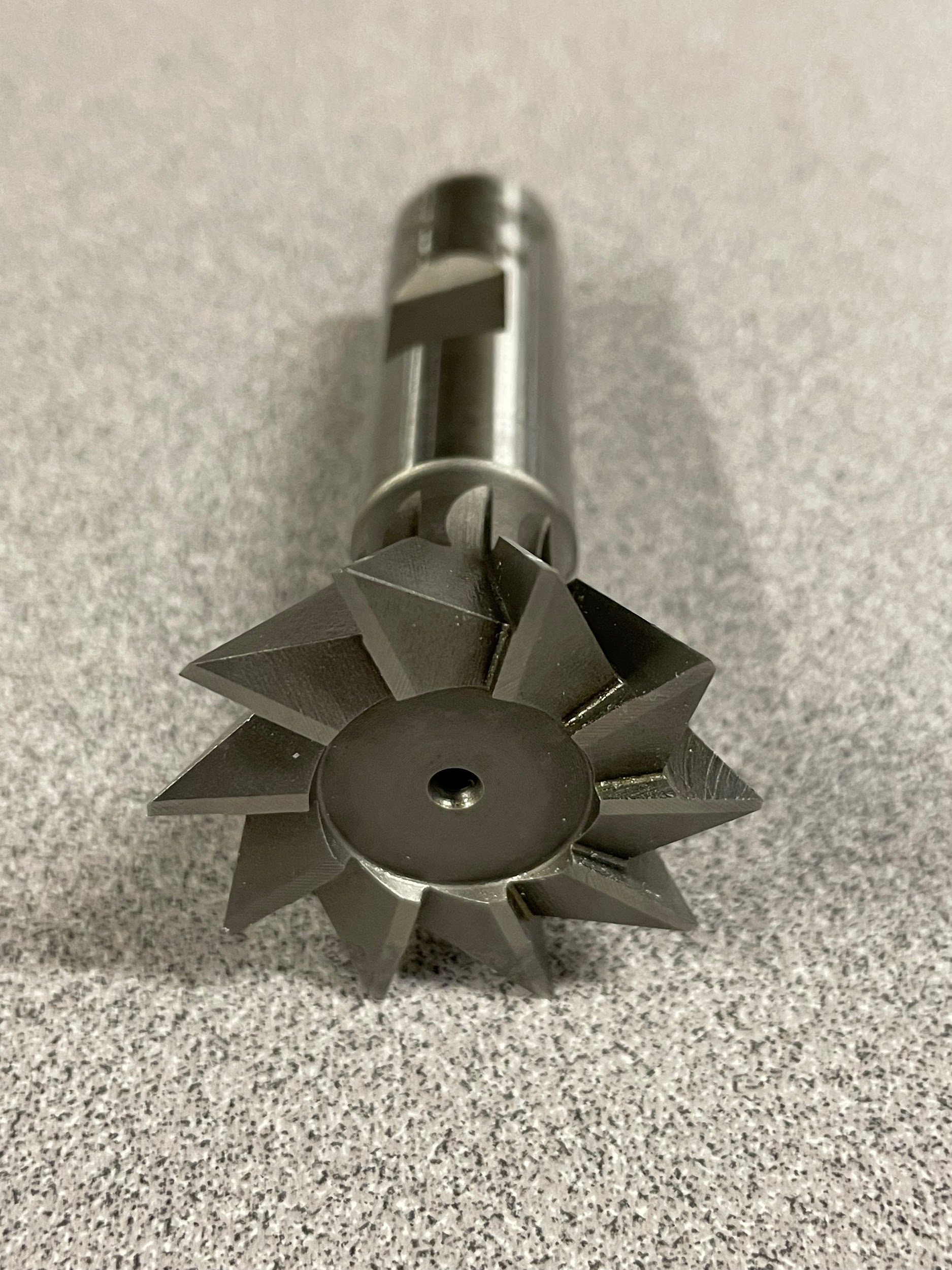
A form tool is a specialty tool that has the exact shape needed on the part already formed into the shape of the tool. This allows for a single pass to create critical and difficult to machine features in most instances. Some examples of standard form tools would be radius tools, woodruff key cutters, tee slot cutters, and dovetail cutters. Custom form tools can be any shape the tool maker can think of to make the production of a part easier. Think of door and window molding used in a home. Most moldings have a slightly different shape. Each different shape has a different router bit profile to create it. This same concept is used on custom form tools for milling machines.
Hole-making Tools
Hole-making tools, such as drills, reamers, taps, countersinks, and counterbores, previously discussed in the drill press chapter, are also utilized on the milling machine.
Attributions
- Figure 9.101: Two end mills, two materials by Micky R. Jennings, courtesy of Wenatchee Valley College, for WA Open ProfTech, © SBCTC, CC BY 4.0
- Figure 9.102: Face mill by Micky R. Jennings, courtesy of Wenatchee Valley College, for WA Open ProfTech, © SBCTC, CC BY 4.0
- Figure 9.103: Face mill 2 by Micky R. Jennings, courtesy of Wenatchee Valley College, for WA Open ProfTech, © SBCTC, CC BY 4.0
- Figure 9.104: Face mill 3 by Micky R. Jennings, courtesy of Wenatchee Valley College, for WA Open ProfTech, © SBCTC, CC BY 4.0
- Figure 9.105: Two flute finishing end mill by Micky R. Jennings, courtesy of Wenatchee Valley College, for WA Open ProfTech, © SBCTC, CC BY 4.0
- Figure 9.106: Two flute finishing end mill 2 by Micky R. Jennings, courtesy of Wenatchee Valley College, for WA Open ProfTech, © SBCTC, CC BY 4.0
- Figure 9.107: Four flute finishing end mill by Micky R. Jennings, courtesy of Wenatchee Valley College, for WA Open ProfTech, © SBCTC, CC BY 4.0
- Figure 9.108: Four flute finishing end mill 2 by Micky R. Jennings, courtesy of Wenatchee Valley College, for WA Open ProfTech, © SBCTC, CC BY 4.0
- Figure 9.109: Four flute roughing end mill by Micky R. Jennings, courtesy of Wenatchee Valley College, for WA Open ProfTech, © SBCTC, CC BY 4.0
- Figure 9.110: Four flute roughing end mill 2 by Micky R. Jennings, courtesy of Wenatchee Valley College, for WA Open ProfTech, © SBCTC, CC BY 4.0
- Figure 9.111: Indexable insert end mills by Micky R. Jennings, courtesy of Wenatchee Valley College, for WA Open ProfTech, © SBCTC, CC BY 4.0
- Figure 9.112: Indexable insert end mill by Micky R. Jennings, courtesy of Wenatchee Valley College, for WA Open ProfTech, © SBCTC, CC BY 4.0
- Figure 9.113: Ball end mill by Micky R. Jennings, courtesy of Wenatchee Valley College, for WA Open ProfTech, © SBCTC, CC BY 4.0
- Figure 9.114: Ball end mill 2 by Micky R. Jennings, courtesy of Wenatchee Valley College, for WA Open ProfTech, © SBCTC, CC BY 4.0
- Figure 9.115: Bull end mill by Micky R. Jennings, courtesy of Wenatchee Valley College, for WA Open ProfTech, © SBCTC, CC BY 4.0
- Figure 9.116: Bull end mill 2 by Micky R. Jennings, courtesy of Wenatchee Valley College, for WA Open ProfTech, © SBCTC, CC BY 4.0
- Figure 9.117: Boring head by Micky R. Jennings, courtesy of Wenatchee Valley College, for WA Open ProfTech, © SBCTC, CC BY 4.0
- Figure 9.118: Boring head 2 by Micky R. Jennings, courtesy of Wenatchee Valley College, for WA Open ProfTech, © SBCTC, CC BY 4.0
- Figure 9.119: Boring head 3 by Micky R. Jennings, courtesy of Wenatchee Valley College, for WA Open ProfTech, © SBCTC, CC BY 4.0
- Figure 9.120: Slitting saw by Micky R. Jennings, courtesy of Wenatchee Valley College, for WA Open ProfTech, © SBCTC, CC BY 4.0
- Figure 9.121: Corner rounding tool by Micky R. Jennings, courtesy of Wenatchee Valley College, for WA Open ProfTech, © SBCTC, CC BY 4.0
- Figure 9.122: Corner rounding tool 2 by Micky R. Jennings, courtesy of Wenatchee Valley College, for WA Open ProfTech, © SBCTC, CC BY 4.0
- Figure 9.123: Woodruff key cutter by Micky R. Jennings, courtesy of Wenatchee Valley College, for WA Open ProfTech, © SBCTC, CC BY 4.0
- Figure 9.124: Woodruff key cutter 2 by Micky R. Jennings, courtesy of Wenatchee Valley College, for WA Open ProfTech, © SBCTC, CC BY 4.0
- Figure 9.125: Dovetail cutter by Micky R. Jennings, courtesy of Wenatchee Valley College, for WA Open ProfTech, © SBCTC, CC BY 4.0
- Figure 9.126: Dovetail cutter 2 by Micky R. Jennings, courtesy of Wenatchee Valley College, for WA Open ProfTech, © SBCTC, CC BY 4.0
A milling tool used to cut large flat features perpendicular to the table.
A milling tool that performs side milling, slotting, pocketing, and various other cutts.
A tool that is used to create bored holes on machines that utilize revolving cutters.
A milling tool that is used to create thin linear cuts with circular saw blades.
A tool that is used to cut a specific shape on a part, often in a single linear cut. The tool is made to be the inverse of the shape required on the part.
