9.9 Spindle Speed, Feed Rate, Depth Of Cut And Finish Allowances
Micky R. Jennings
Spindle Speed
Milling machines have the same spindle speed calculation as the rest of the rotational tools in the shop. Based on surface feet per minute (SFPM) of a tool and the cutting conditions, the operator can calculate the appropriate RPM.
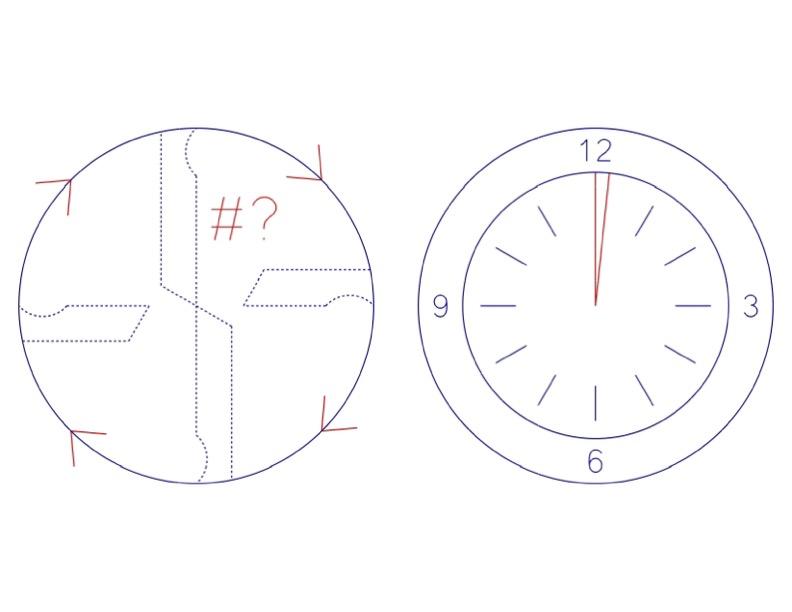
RPM = SFPM × 4 / Diameter
Milling machines are machine tools that can utilize carbide tooling. In these instances, it is always a good idea to consult the manufacturer for the correct surface feet per minute for the tool in a specific material. If there is no technical data on the tool to be used available, a conservative starting point would be 4x the SFPM of HSS.
For example, the calculation for cutting mild steel with a 1/4 carbide end mill would be:
RPM = SFPM × 4 / Diameter
RPM = 400 × 4 / .25
RPM = 1600 / .25
RPM = 6400
Another example is the calculation for cutting aluminum with a 3/4 HSS end mill.
RPM = SFPM × 4 / Diameter
RPM = 200 × 4 / .75
RPM = 800 / .75
RPM = 1066
Feed Rate
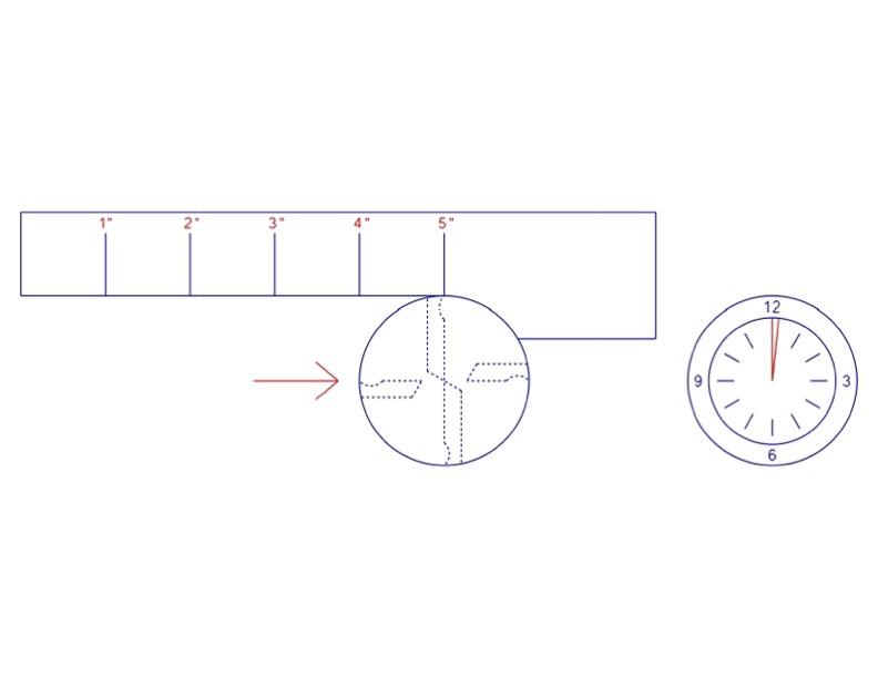
Manual milling machines have a side cutting feed rate that is expressed in Inches Per Minute (IPM). This feed rate is completely independent of the rotation of the spindle. The formula to calculate the feed rate is:
IPM = RPM × number of flutes × Chip Load Per Tooth (CPT)
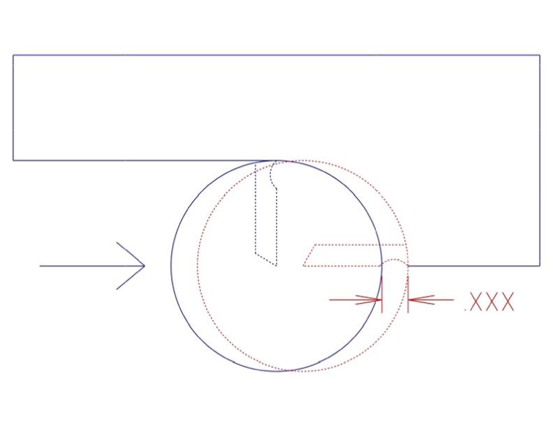
The chip load per tooth (CPT) is another area where the manufacturer will have some helpful information about their product. If that information isn’t available, the following generalized conservative estimate can be used to get the operator started.
CPT = Diameter / 1/8 × .0005 to .001
As the tool size gets larger and stronger, more CPT can be taken with the tool without damaging it.
For example, let’s calculate roughing out aluminum with a 2 flute 1/2″ carbide end mill.
First, the RPM:
RPM = SFPM × 4 / Diameter
RPM = 400 × 4 / .5
RPM = 1600 / .5
RPM = 3200
Now the CPT:
CPT = Diameter / 1/8 × .001
CPT = 1/2 / 1/8 × .001
CPT = 4 × .001
CPT = .004
Now the feed rate formula can be calculated:
IPM = RPM × FLTS × CPT
IPM = 3200 × 2 × .004
IPM = 25.6
Author’s Tip
Whenever I am calculating spindle speed in RPM or feed rate in IPM, I take my answer and round it to the nearest 50 RPMs or nearest whole IPM. This makes sense for manual equipment because the machine isn’t accurate to single RPMs or decimal points of IPM, but it will also make sense later on if you utilize a CAM system to aid you in writing technical programs for CNC machines. This rounding generally won’t hurt the tool or the part.
Depth of Cut
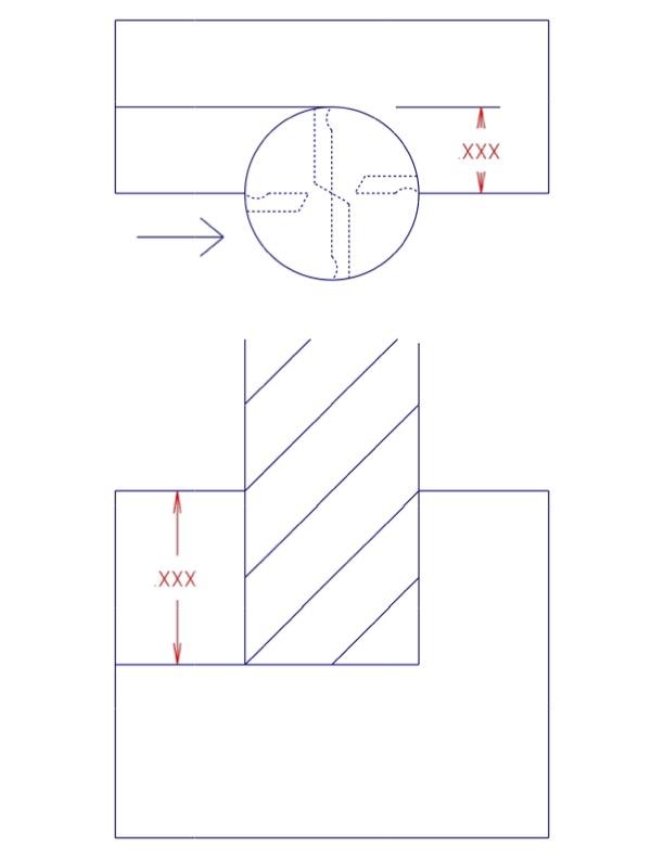
Depth of cut is the amount of the tool engaged in the work while making a cut. On a milling machine, the depth of cut can be axially or radially measured. Depth cuts axially use the tip of the tool more heavily and have a tendency to wear the tool out prematurely. Radial depth cuts use a larger portion of the cutting edges and are generally preferable as the tool will last longer.
On manual milling machines, heavy depth cuts in steel are best performed with roughing end mills. In aluminum, depth cuts can be taken with standard finishing end mills. Aluminum cuts more freely, and the machine can handle the forces of the cuts much better than large steel cuts.
Roughing cuts in steel and aluminum can be taken at 1x diameter radially and ½x diameter axially, or ½x diameter radially and 1x diameter axially. This is just a starting point. The operator can adjust to suit different machines and situations.
For example, when roughing the side of a ½” thick piece of steel with a ½” HSS roughing end mill, the operator could cut ¼” step over at the entire ½” thickness of the material.
Another example is roughing a 1″ slot, 1″ deep, in aluminum, with a ¾” end mill. In this case, the operator could cut the full width of the endmill at ⅜” depth cuts.
Finishing Allowance
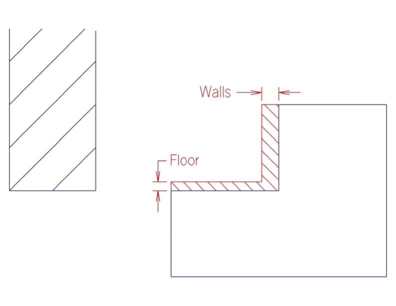
The finishing allowance is the intentional amount of material left on surfaces by the roughing tool. Leaving an allowance for finishing is essential for getting a quality final cut. If too much material is left for finishing, the surface finish and/or accuracy may suffer. If too little material is left, the finishing tool may not completely clean up what the roughing tool left behind. Following a few basic guidelines, and experimentation, the machinist will have success.
When using roughing end mills, the machinist should leave 1/32″ to 1/16″ on the walls and 1/64″ on the floor of features. This is because the rough texture left by roughing end mill leaves is deceiving and impossible to measure accurately. After the roughing end mill removes material, a finish end mill will need to be used to clean up the sides before an accurate measurement can be made and the true finish pass can be executed.
When cutting with a finish style end mill for roughing cuts, the operator should leave around 1/64″ on the wall and floor of features. Finish style end mills are much more capable of accurate cuts than roughing end mills. These values can also be used for a semi finish pass after using a roughing cutter.
In between the roughing and finishing passes, the operator should accurately measure the part to make sure they know how much material is remaining and calculate how to adjust the machine to remove the excess material.
The finish pass should take the final amount off the walls and floor simultaneously so that the tool only runs across the surfaces one time.
Conventional Milling and Climb Milling
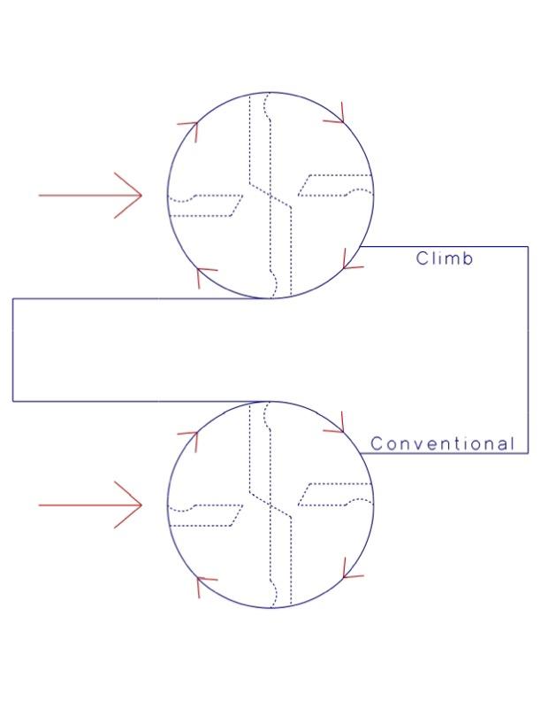
Conventional milling and climb milling are different ways to remove material when cutting with the side of a milling tool. It is important to know the difference because it can determine whether an accurate part with good surface finishes or a rough-looking scrap part and/or potential broken tooling will result.
Conventional milling happens when the base material is moving in the opposite direction as the cutting teeth. This method of cutting often leaves a poor finish. This is because any chips that may get recut and pounded into the surface will do so at a position where the cutter is entering the finished part. When chip fragments are imbedded into the surface the finished part appears cloudy or rough. The cutter enters the material at its thinnest point on the part’s surface and exits at the full chip load thickness at the point where the chip is removed. Although the finish isn’t great, this is a much safer cut on a manual milling machine. This is because the cutting action of the tool is pushing directly against the lead screw, keeping the backlash out of the equation. Conventional milling is great for all the roughing operations that need to be made on a manual mill.
Climb milling happens when the base material is moving in the same direction as the cutting teeth. This method of cutting leaves the best finish. This is because any chips that may get recut and pounded into the surface will do so in a position where the cutter is entering waste material. The cutter enters the material at the full chip load amount and exits thin at the finished part surface. Because the work is moving in the same direction as the cutting teeth, machines with backlash will have a tendency to automatically pull the material into the backlash slop. This involuntary movement prematurely increases the size of the chip load, causing a runaway chain reaction that could break the cutter and ruin the part. For this reason, climb milling on manual machines is best left for light finishing cuts of no more than 1/64″.
Traditionally, a machinist will make all the roughing cuts using conventional milling, leaving .005″ to .015″. Utilize precision measuring techniques while the part is still in the machine. Then climb mill the remaining material for a finish pass.


Attributions
- Figure 9.132: Rotation per minute – milling machine by Micky R. Jennings, courtesy of Wenatchee Valley College, for WA Open ProfTech, © SBCTC, CC BY 4.0
- Figure 9.133: Feed rate – milling machine by Micky R. Jennings, courtesy of Wenatchee Valley College, for WA Open ProfTech, © SBCTC, CC BY 4.0
- Figure 9.134: Chipload per tooth – milling machine by Micky R. Jennings, courtesy of Wenatchee Valley College, for WA Open ProfTech, © SBCTC, CC BY 4.0
- Figure 9.135: Depth of cut – milling machine by Micky R. Jennings, courtesy of Wenatchee Valley College, for WA Open ProfTech, © SBCTC, CC BY 4.0
- Figure 9.136: Finishing allowance – mill by Micky R. Jennings, courtesy of Wenatchee Valley College, for WA Open ProfTech, © SBCTC, CC BY 4.0
- Figure 9.137: Climb vs conventional illming – milling machine by Micky R. Jennings, courtesy of Wenatchee Valley College, for WA Open ProfTech, © SBCTC, CC BY 4.0
- Video 9.21: Micky R. Jennings, courtesy of Wenatchee Valley College, for WA Open ProfTech, © SBCTC, CC BY 4.0
- Video 9.22: Micky R. Jennings, courtesy of Wenatchee Valley College, for WA Open ProfTech, © SBCTC, CC BY 4.0
The rate at which a spindle is rotating. Often expressed in rotations per minute (RPM).
The rate at which a machine axis is moving. Often expressed in inches per minute (IPM).
The amount a cutting tool is engaged in the material as measured along an axis perpendicular to the cutting axes.
The amount of material that is intentionally left after roughing operations, for finishing passes.
