9.16 Radius Cutting
Micky R. Jennings

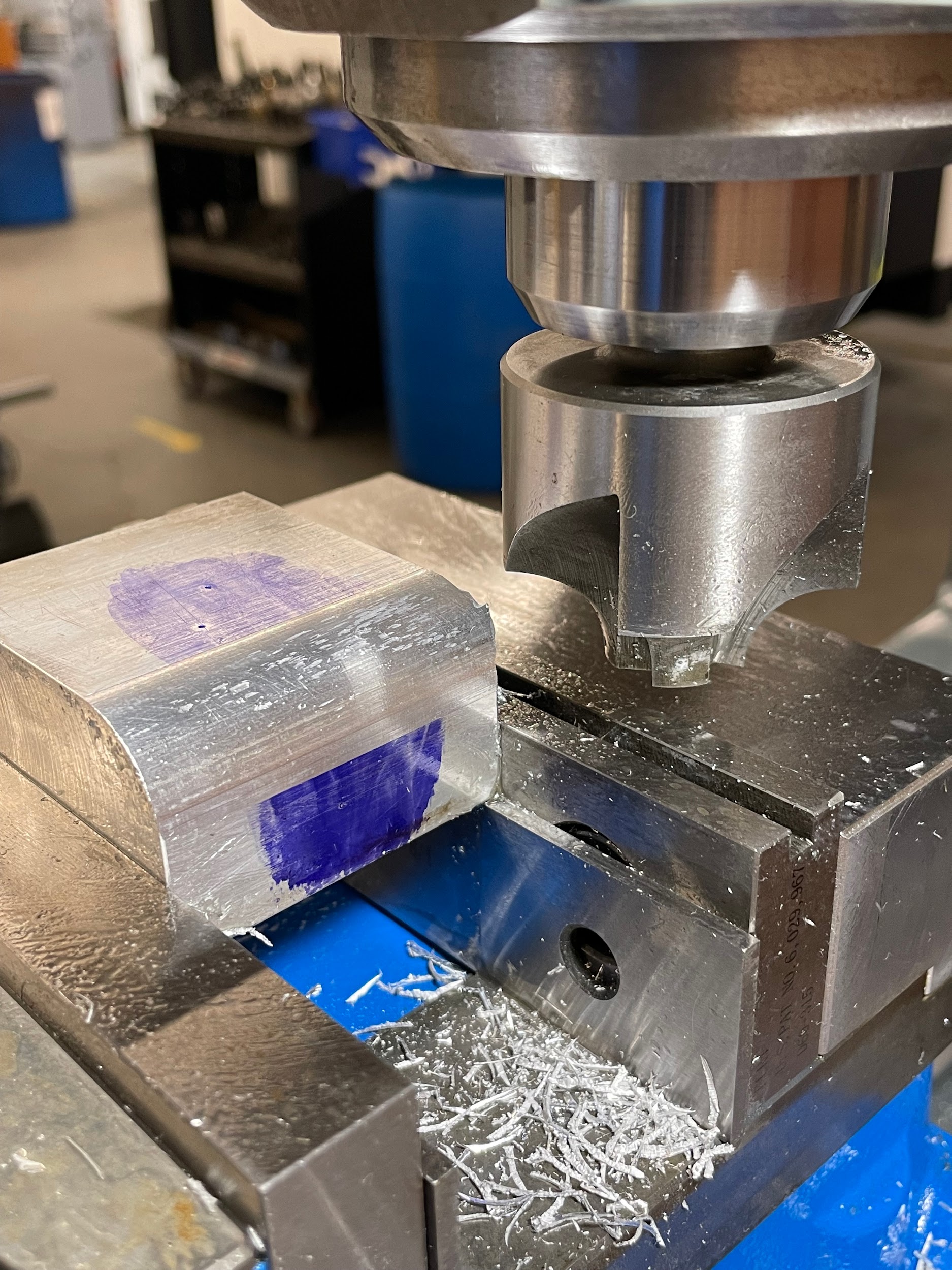
Radius cutting is the process of creating a radius on an edge with a corner rounding tool. This radius is most often created on a 90-degree corner. These cuts are used to remove corners that might be damaging to other components, as a design element, or simply for aesthetic reasons.
Step by step process for radius cutting:
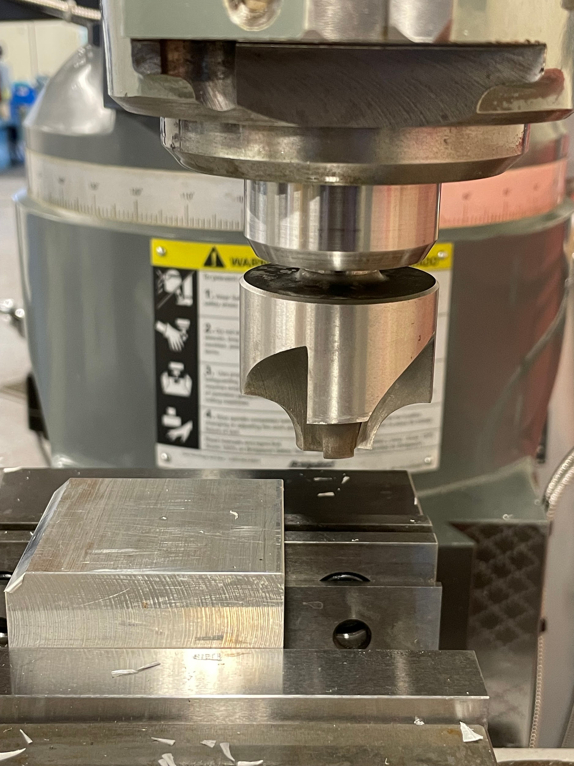
- Load a corner rounding milling tool into the milling spindle.
- Calculate the spindle speed for the maximum diameter of the work the tool will contact. The spindle speed for form milling is generally 1/4 of the speed of standard milling due to the amount of tool in contact with the work. The longer the linear length of cutting edge touching the work, the greater the chance for chatter to occur.
- Touch off the top edge of the radius tool.
-
- Feeler gage
-
-
- Touch the flat edge of the tool to the face of the work using the knee and a feeler gage.
- Set the knee hand wheel to zero.
- Back the tool off the part by moving the table.
- Raise the knee by the amount of the feeler gage and re-zero the knee.
-
-
- Layout dye
-
-
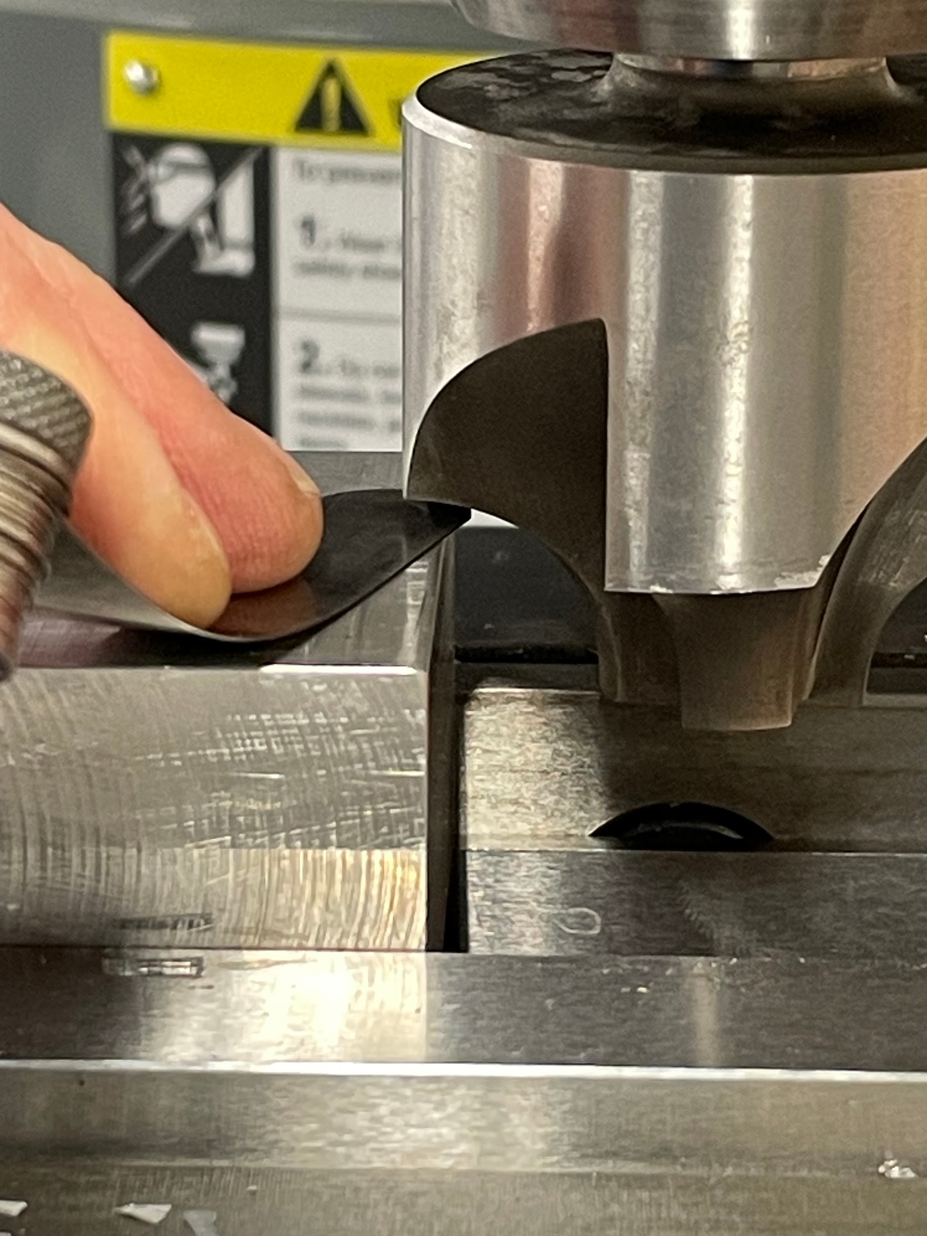
- Touch-off the tool to the top of the work to remove the dye.
- Set the knee hand wheel to zero.
-
- Touch off the center edge of the radius tool.
-
- Feeler gage
-
-
- Touch the end diameter of the tool to the side of the work using the table and a feeler gage.
- Set the table hand wheel to zero.
- Back the tool off the part by moving the knee.
- Move the table by the amount of the feeler gage and re-zero the table.
-
-
- Layout dye
-
-
- Touch-off the tool to the side of the work to remove the dye.
- Set the table hand wheel to zero.
-
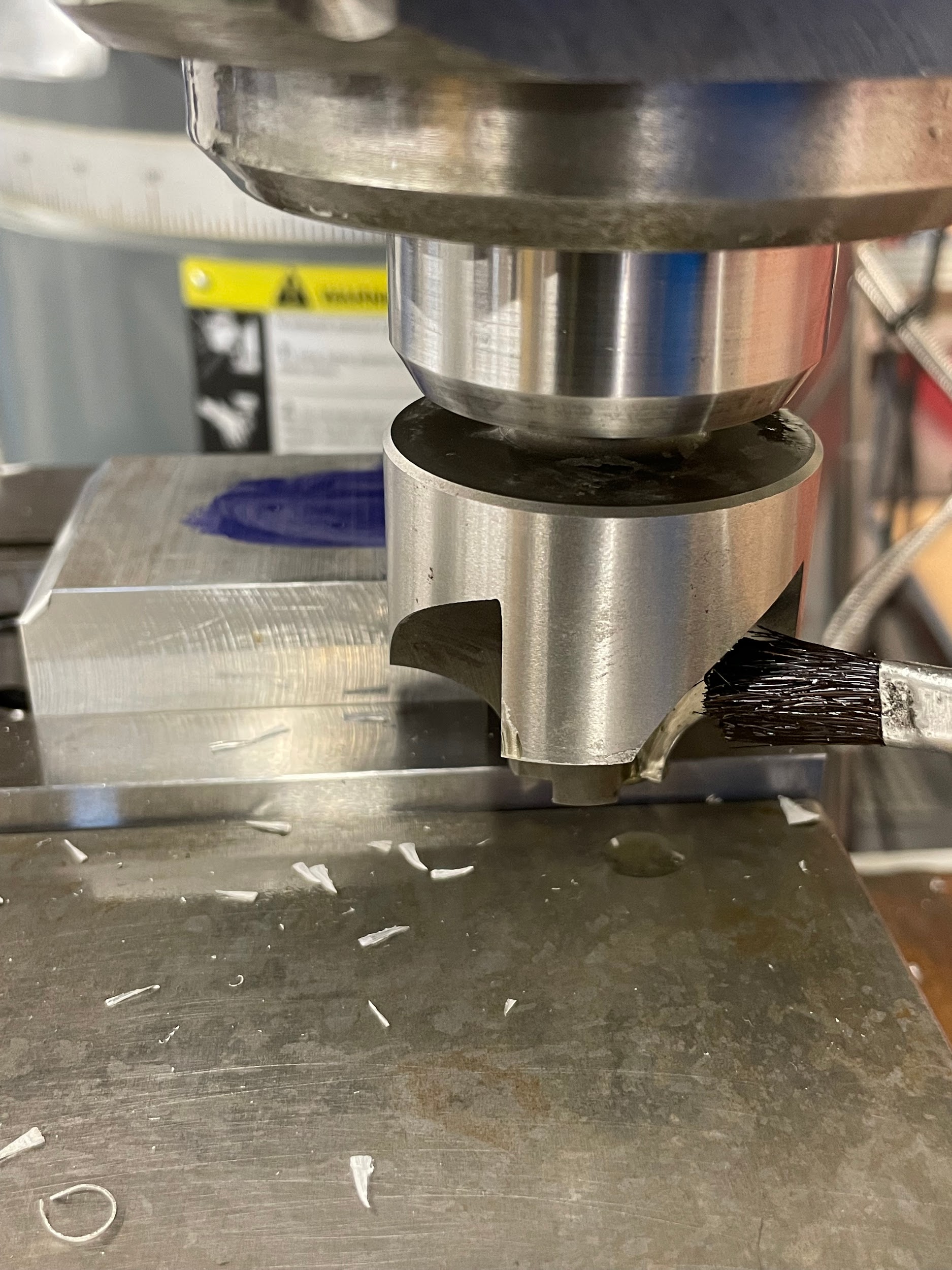
- Lube the tool.
- Start the spindle and adjust the speed.
- For a small radius, it may be created in one cut, whereas a larger radius may require multiple cuts. Adjust the cutting tool depth accordingly.
- Cut across the length of the material.
- Similarly, perform the remaining cuts while making depth changes with the handwheels toward their zero point.
- Back the tool off and measure with a radius gage.
Step 1: Load a corner rounding milling tool into the milling spindle.
Step 3-a-i: Touch the flat edge of the tool to the face of the work using the knee and a feeler gage.
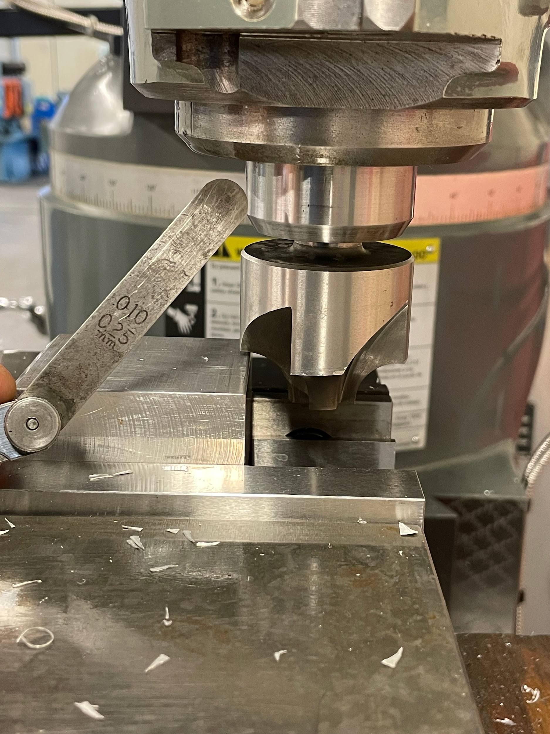
Step 3-a-i: Touch the flat edge of the tool to the face of the work using the knee and a feeler gage.
Step 3-a-i: Touch the flat edge of the tool to the face of the work using the knee and a feeler gage.”

Step 4-a-i: Touch the end diameter of the tool to the side of the work using the table and a feeler gage.

Step 3-b-i: Touch-off the tool to the top of the work to remove the dye.

Step 4-b-i: Touch-off the tool to the side of the work to remove the dye.

Step 5: Lube the tool.
Step 9: Similarly, perform the remaining cuts while making depth changes with the handwheels toward their zero point.

Step 9: Similarly, perform the remaining cuts while making depth changes with the handwheels toward their zero point.
Attributions
- Figure 9.210: Radius cut finished by Micky R. Jennings, courtesy of Wenatchee Valley College, for WA Open ProfTech, © SBCTC, CC BY 4.0
- Figure 9.211: Corner rounding tool in spindle by Micky R. Jennings, courtesy of Wenatchee Valley College, for WA Open ProfTech, © SBCTC, CC BY 4.0
- Figure 9.212: Corner rounding tool touch off by Micky R. Jennings, courtesy of Wenatchee Valley College, for WA Open ProfTech, © SBCTC, CC BY 4.0
- Figure 9.213: Corner rounding tool touch off 2 by Micky R. Jennings, courtesy of Wenatchee Valley College, for WA Open ProfTech, © SBCTC, CC BY 4.0
- Video 9.68: Micky R. Jennings, courtesy of Wenatchee Valley College, for WA Open ProfTech, © SBCTC, CC BY 4.0
- Video 9.69: Micky R. Jennings, courtesy of Wenatchee Valley College, for WA Open ProfTech, © SBCTC, CC BY 4.0
- Video 9.70: Micky R. Jennings, courtesy of Wenatchee Valley College, for WA Open ProfTech, © SBCTC, CC BY 4.0
- Video 9.71: Micky R. Jennings, courtesy of Wenatchee Valley College, for WA Open ProfTech, © SBCTC, CC BY 4.0
- Figure 9.214: Lubing a corner rounding tool by Micky R. Jennings, courtesy of Wenatchee Valley College, for WA Open ProfTech, © SBCTC, CC BY 4.0
- Video 9.72: Micky R. Jennings, courtesy of Wenatchee Valley College, for WA Open ProfTech, © SBCTC, CC BY 4.0
- Figure 9.215: Radius cut finished by Micky R. Jennings, courtesy of Wenatchee Valley College, for WA Open ProfTech, © SBCTC, CC BY 4.0
The process of using milling cutters to create radius features on a workpiece.
