9.20 Hole Making
Micky R. Jennings
Hole-making operations on a milling machine are much the same as hole operations on a drill press. Drilling, reaming, tapping, countersinking, and counterboring speeds and feeds are basically the same. The main difference is the extra level of accuracy achievable on the milling machine as opposed to the drill press. On the milling machine, the operator may still layout hole positions, but the layout will be for visual verification only. There will not be any center punching because on the milling machine, the part is held rigidly and in line with the machine’s movements. With precision movements, the operator can use an edge finder or indicators in order to find the accurate positioning of holes and features. This level of accuracy is much more precise than the visual alignment that is done on the drill press.
Another difference on the milling machine is the accuracy of the depths of features that can be achieved. On the milling machine, the operator is able to set the quill stop at the top of the part and then use the accuracy of the knee in order to get the depth accuracy needed. To be clear, the operator is only setting the depth with the knee and then cutting down to the quill stop using similar quill handle motions to break the chips, as on the drill press. It is not customary to make the cutting motion by moving the hand crank of the knee. Not only is it tiring, but it is also difficult to make the quick in-and-out motions that often need to be made to control the chips during hole-making operations.
Countersinking/Counterboring
The following is an example of how hole-making depths could be performed on a manual milling machine.
Step by step process for counterboring:
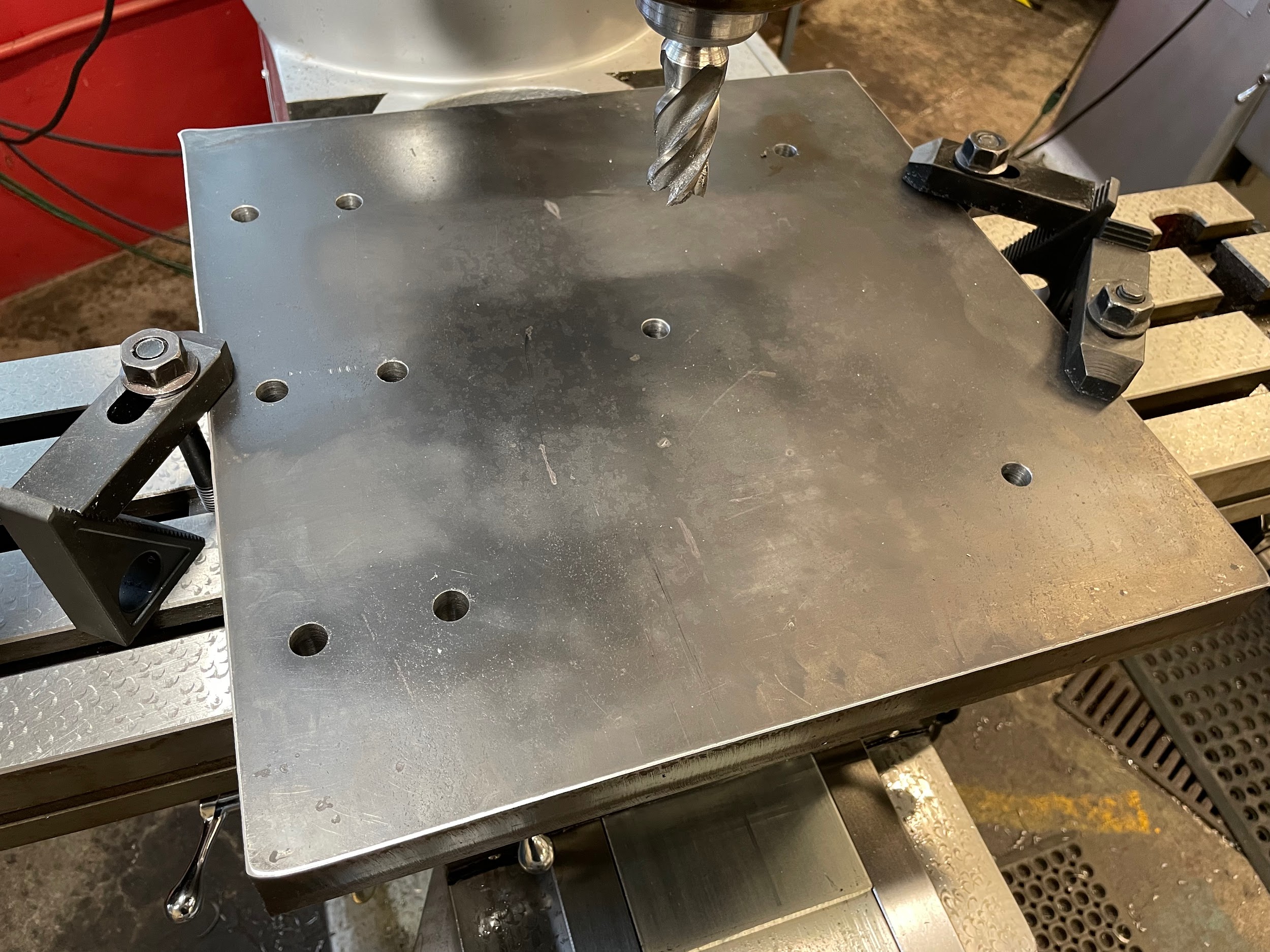
- Load material onto the mill.
- Find accurate hole positions according to the print.
- Lock the saddle and table.
- Spot and drill the appropriate holes.
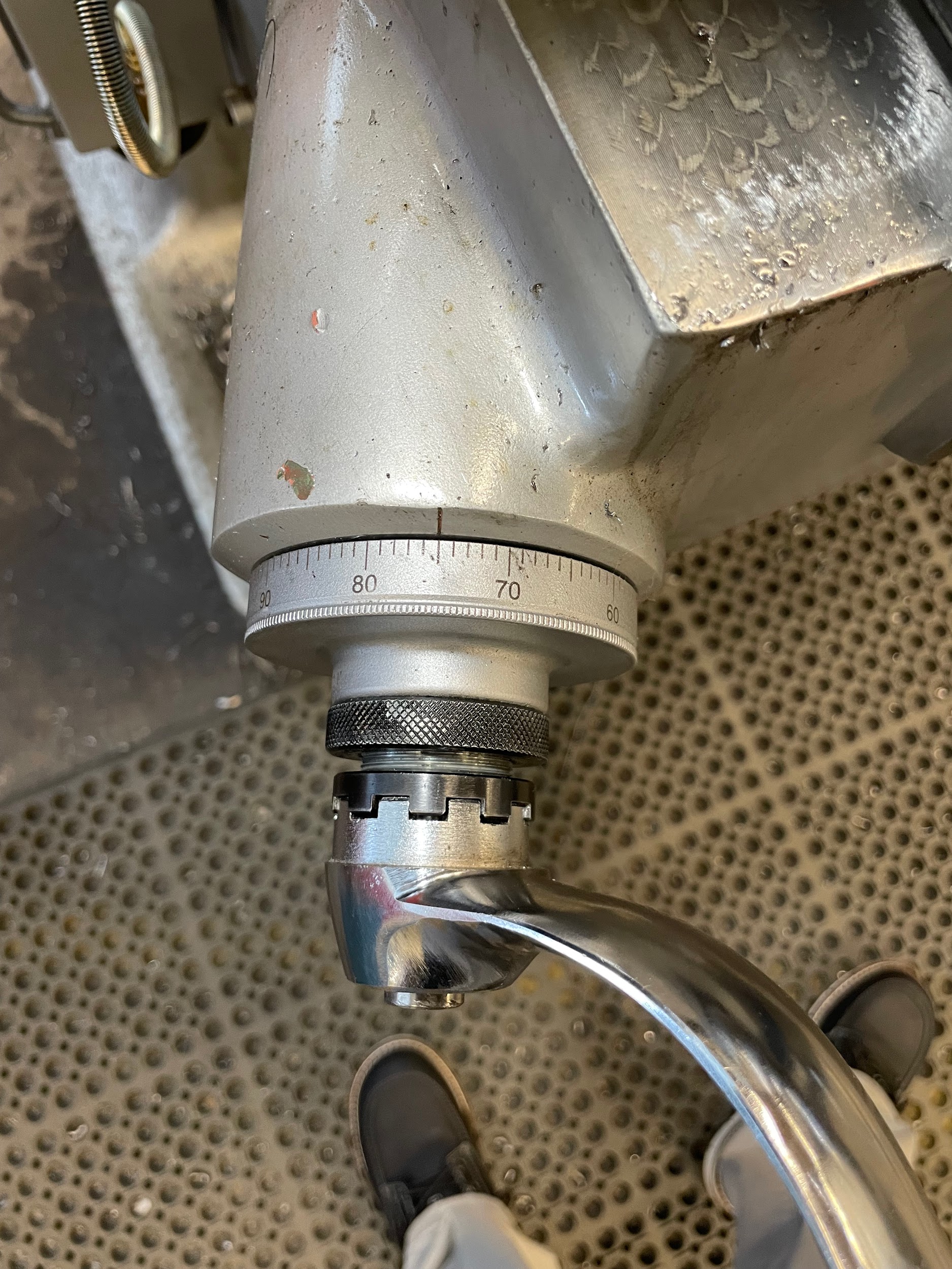
- Load the appropriate counterbore.
- Raise the quill to the top of its stroke.
- Bring the knee up so the top of the material is about ½” further from the tool than the depth required. For instance, if the depth required is ⅜”, bring the knee up so the top of the work is about ⅞” from the tip of the tool.
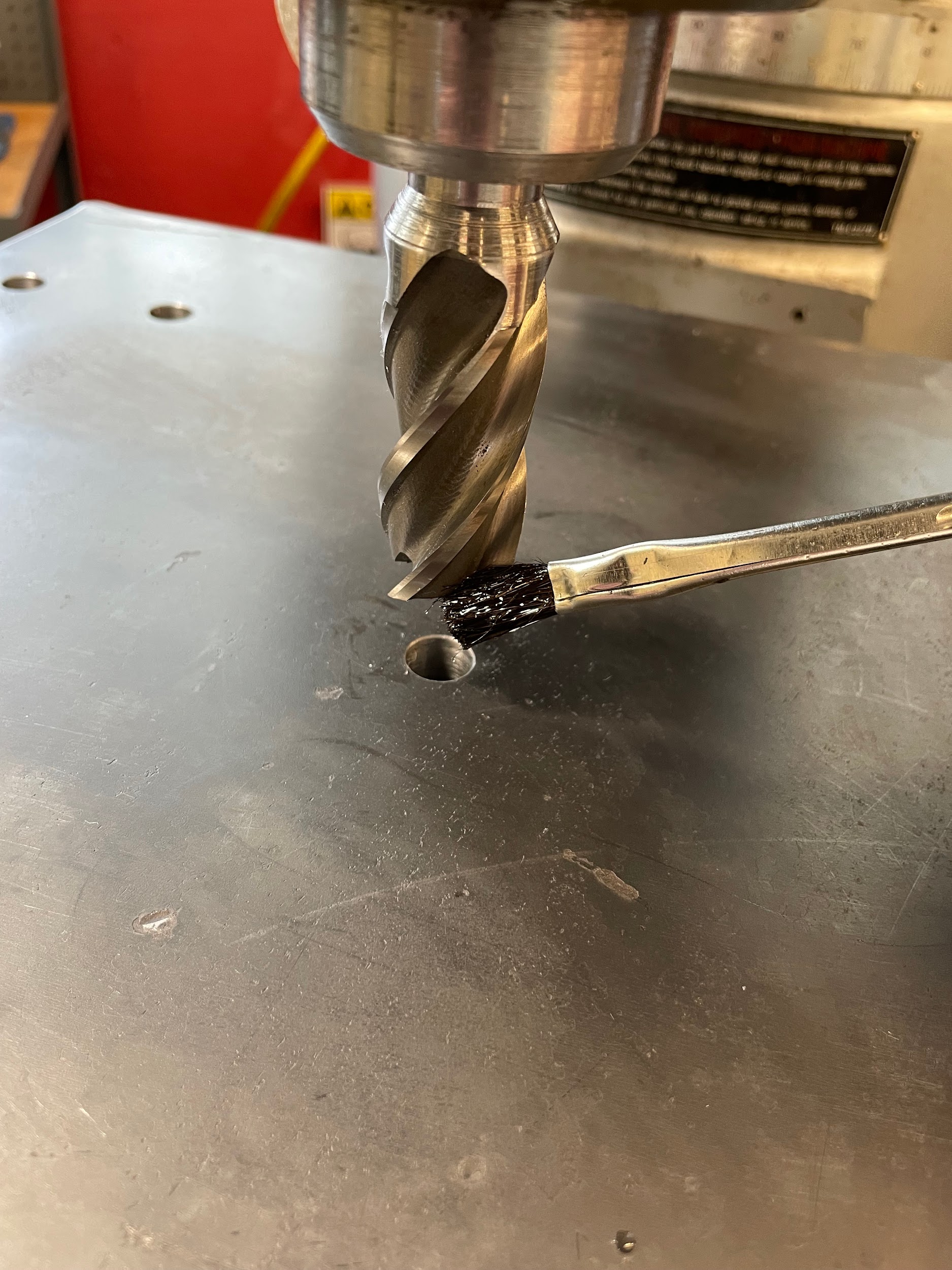
- Bring the tool down to touch the top of the work by gently pulling on the quill handle.
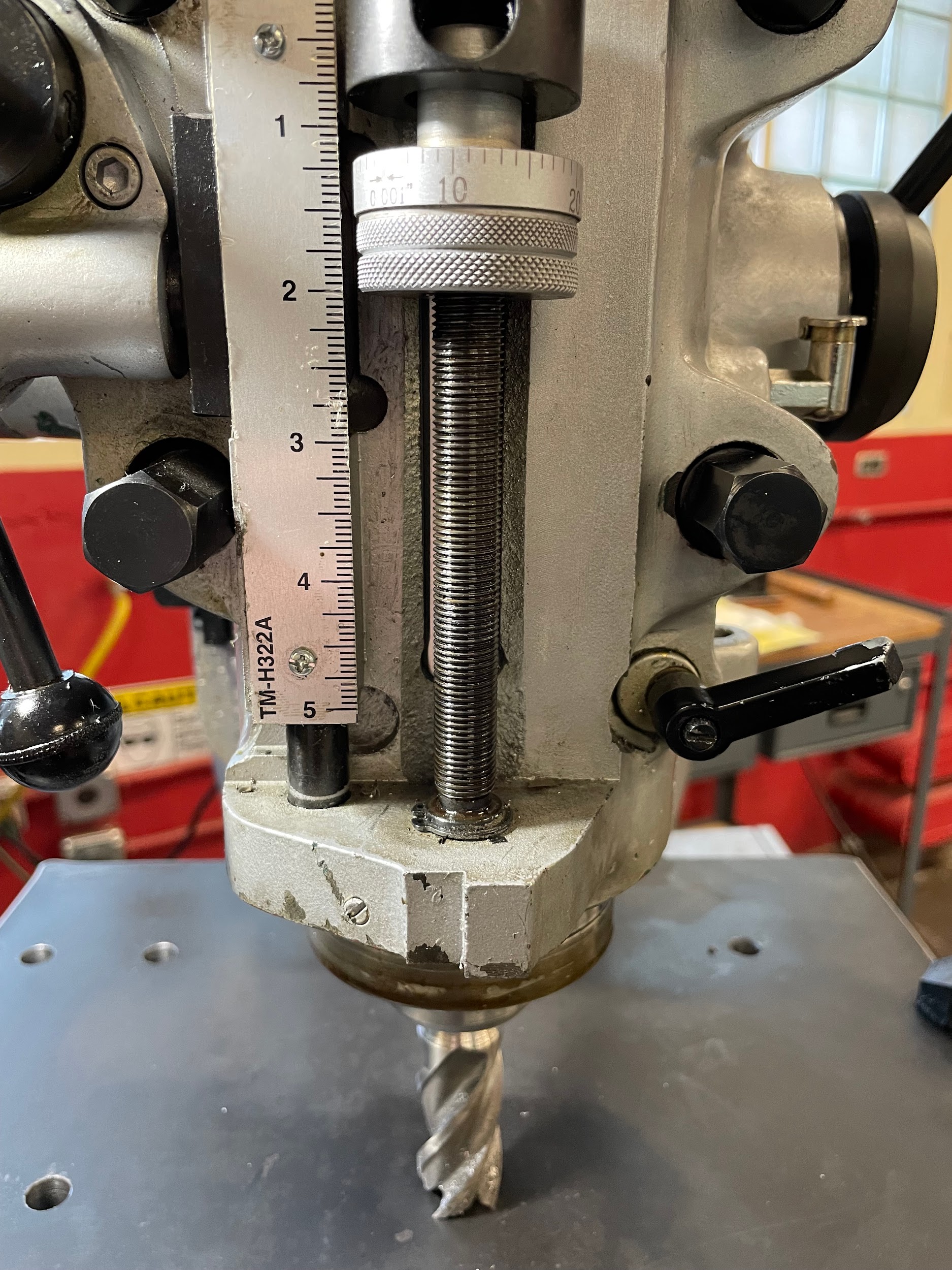
- Adjust the quill stop tight up against the current position of the quill.
- Lock the quill stop.
- Raise the quill up to the top of its stroke again.
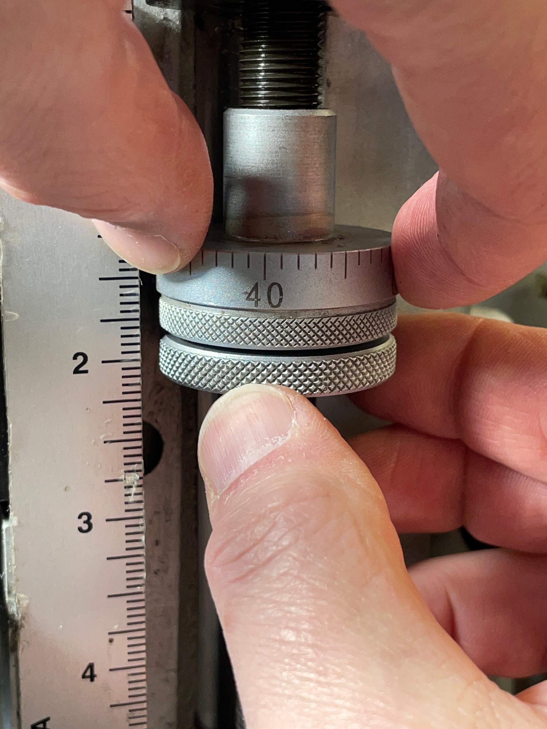
- Raise the knee to the depth of cut required, minus .030″. This will give the operator an opportunity to cut the counterbore shallow, measure the depth, and adjust to get an accurate depth.
- Apply cutting oil.
- Turn the spindle on.
- Adjust the spindle speed.
- Bring the cutter down and make appropriate cuts to depth using the quill handle.
- Turn off the spindle.
- Move the part out from under the tool using the saddle. Move it far enough to accurately measure the hole depth.
- Deburr the top edge of the counterbore.
- Measure the depth.
- The final depth can be adjusted by one of two methods.
- Adjust the quill stop down the remaining amount.
- Adjust the knee up the remaining amount.
- Put the machine back in the hole making position and lock the saddle.
- Start the spindle and cut the remaining amount out of the bottom of the counterbore.
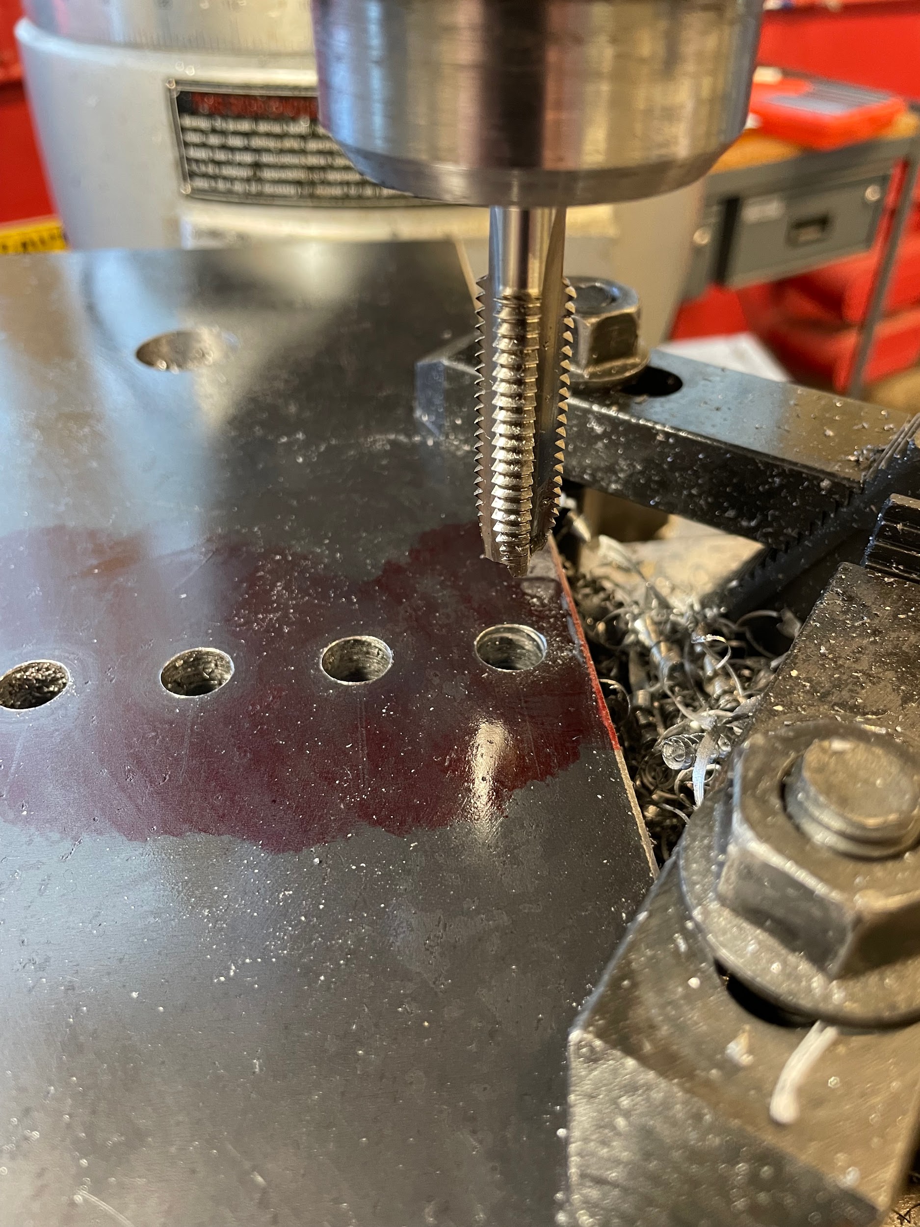
Step 5: Load the appropriate counterbore.
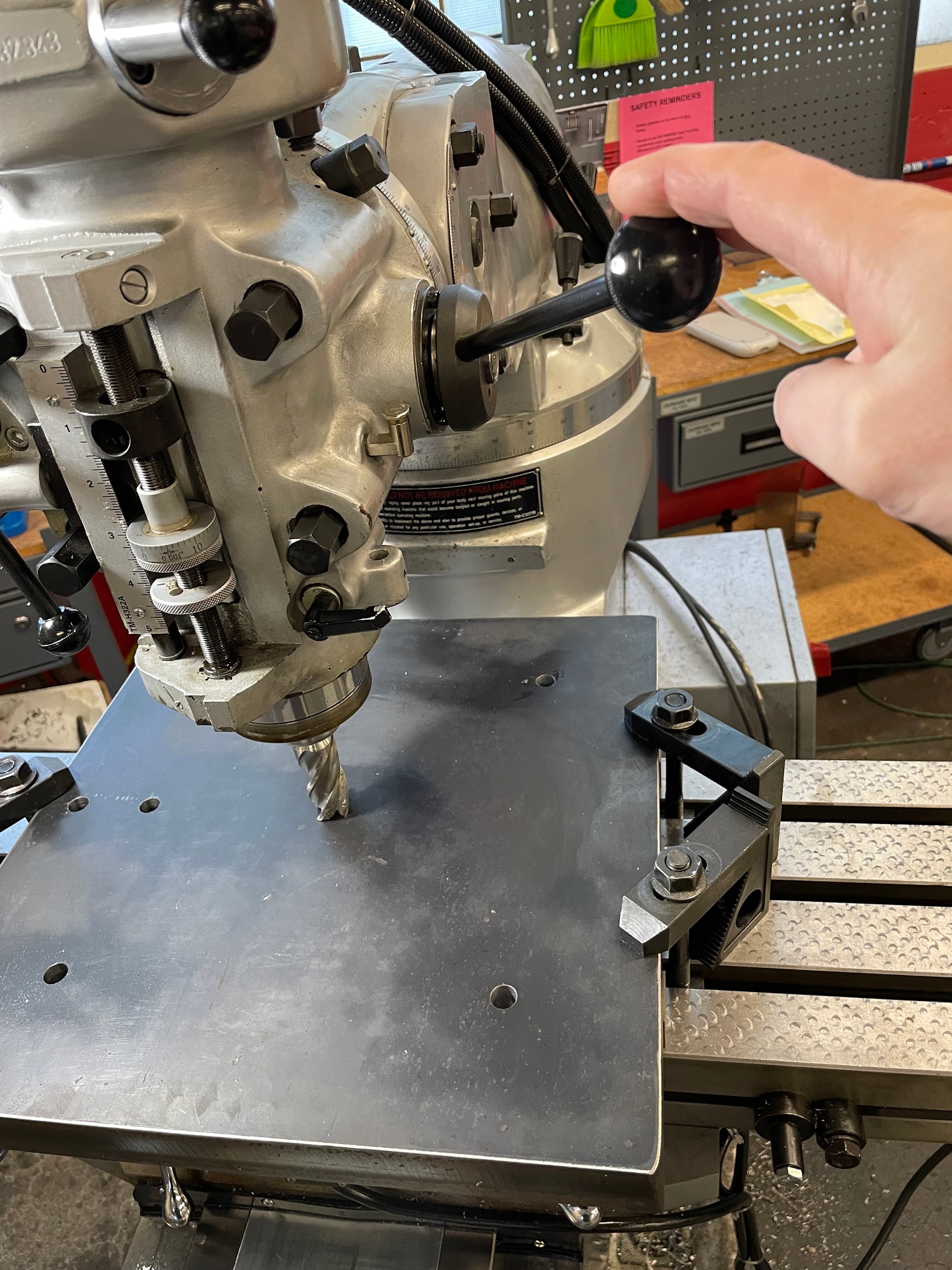
Step 8: Bring the tool down to touch the top of the work by gently pulling on the quill handle.
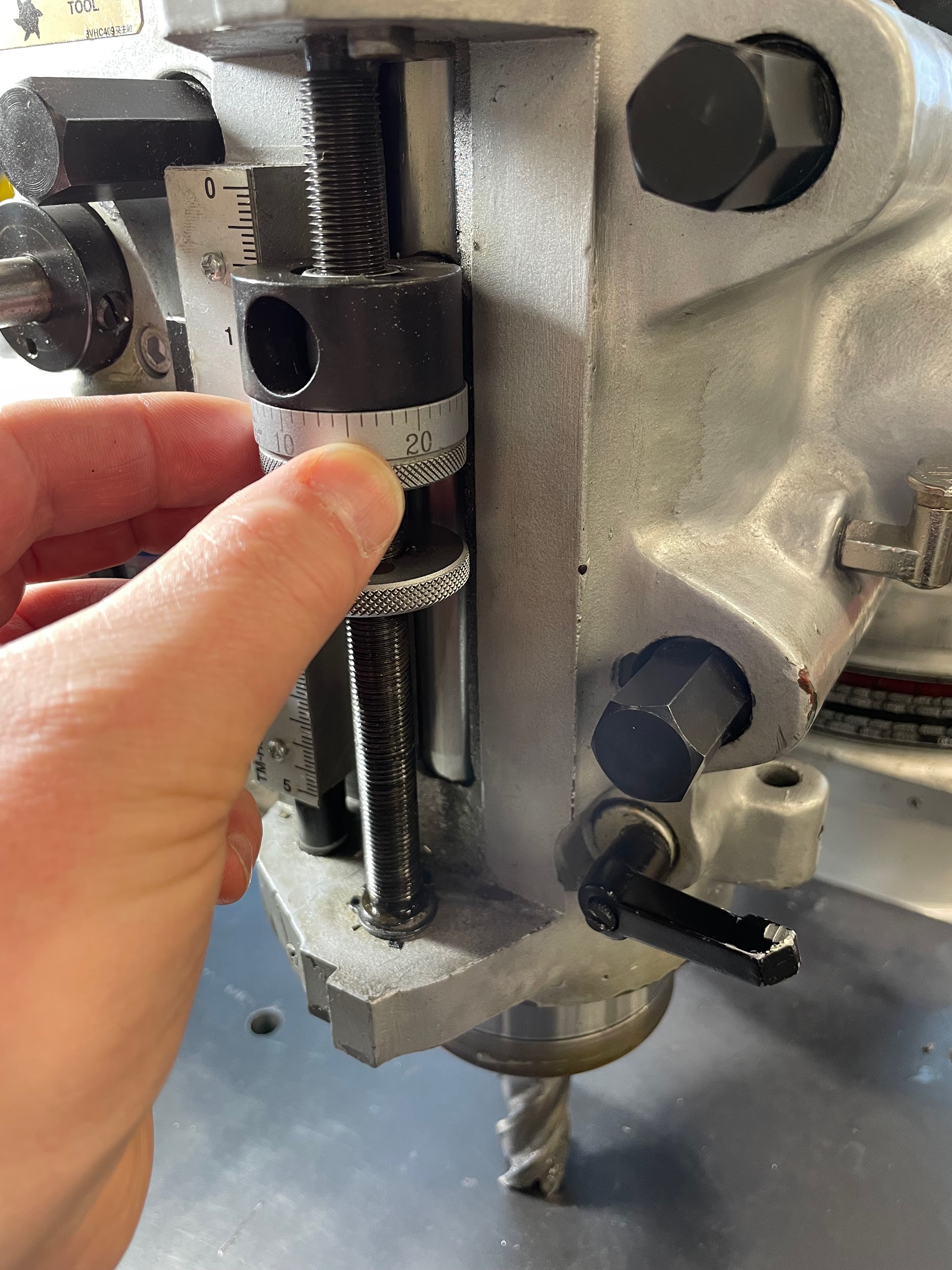
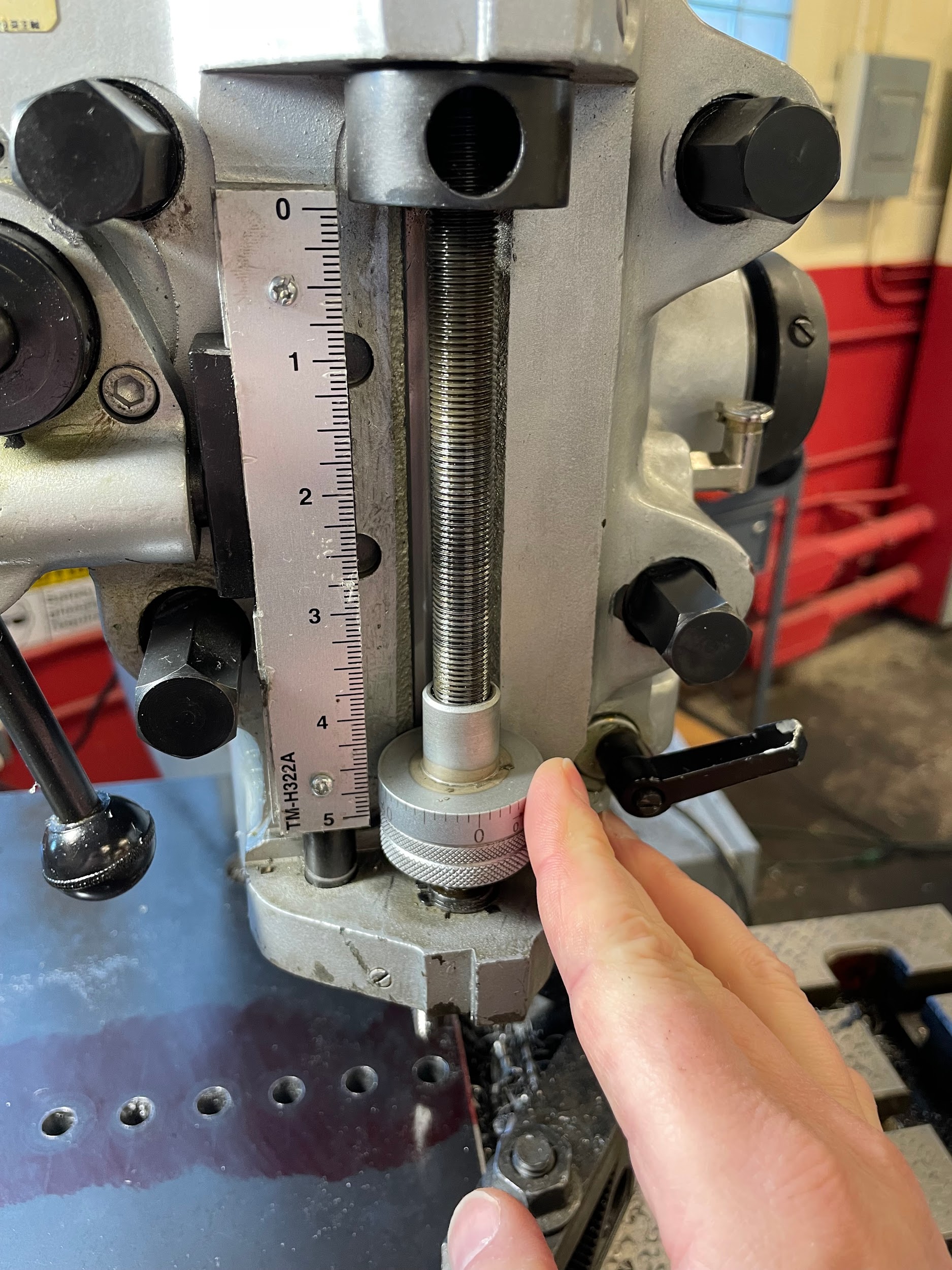
Step 9: Adjust the quill stop tight up against the current position of the quill.
Step 12: Raise the knee to the depth of cut required, minus .030″. This will give the operator an opportunity to cut the counterbore shallow, measure the depth, and adjust to get an accurate depth.
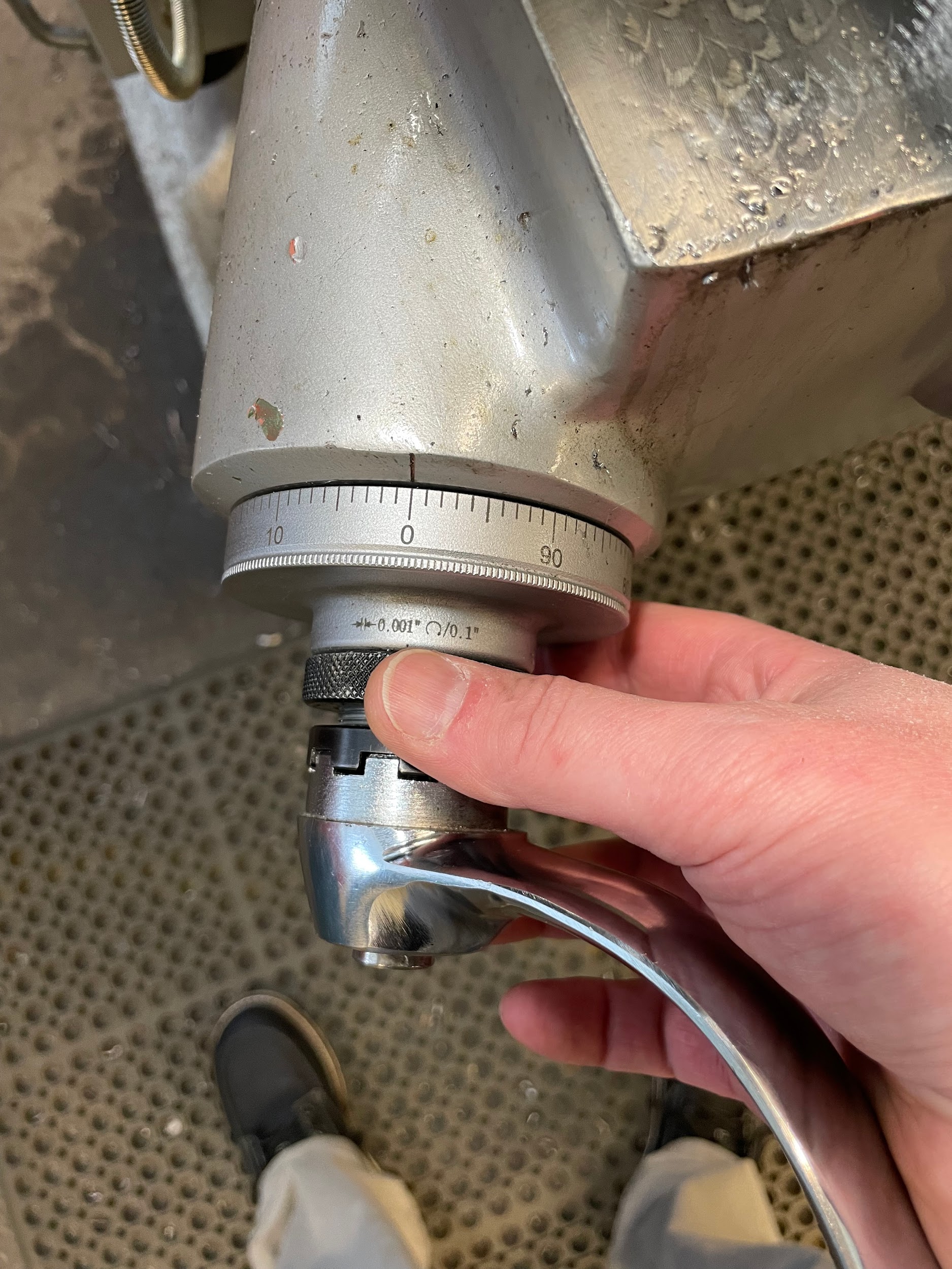
Step 12: Raise the knee to the depth of cut required, minus .030″. This will give the operator an opportunity to cut the counterbore shallow, measure the depth, and adjust to get an accurate depth.
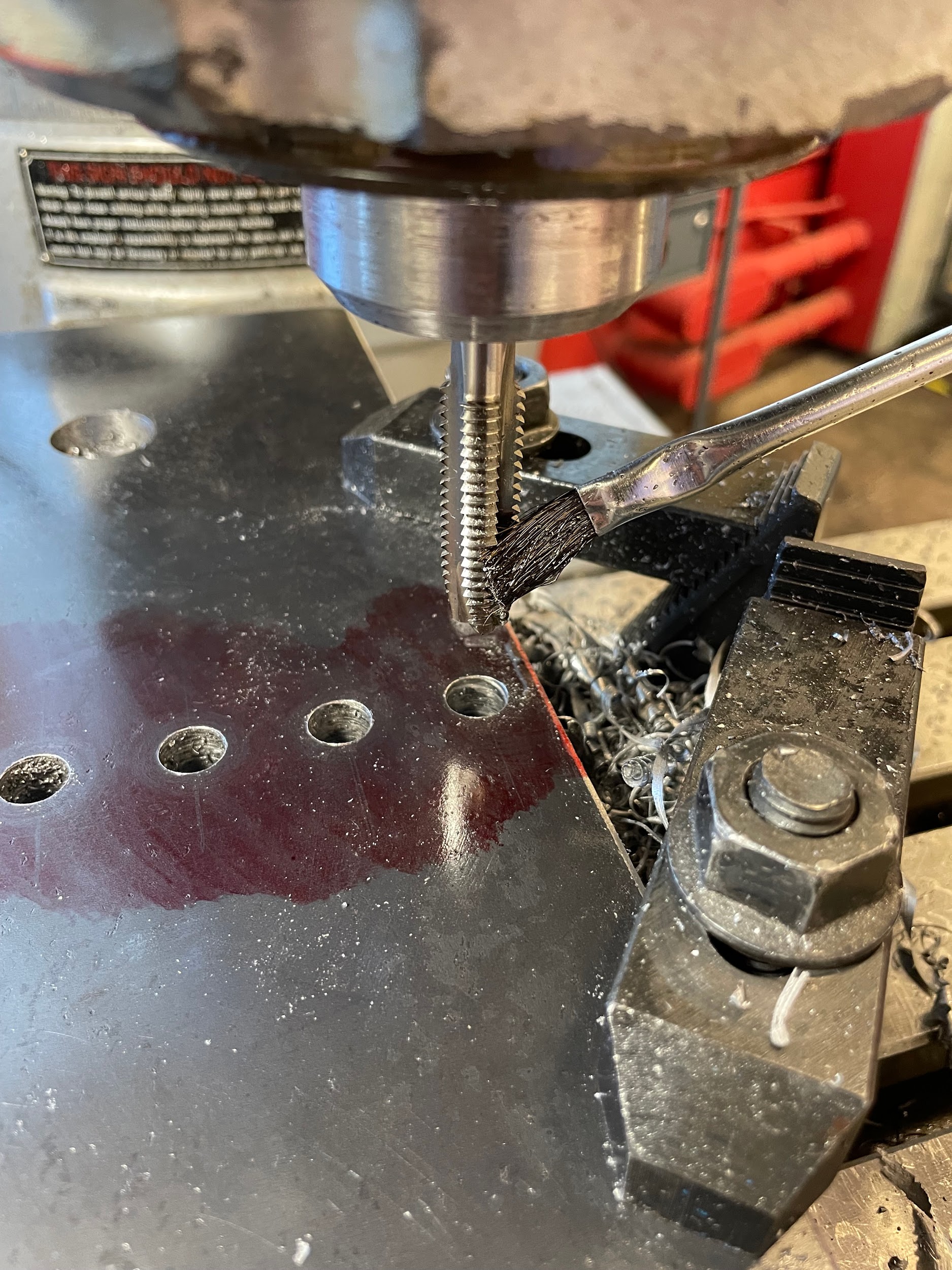
Step 13: Apply cutting oil.
Step 16: Bring the cutter down and make appropriate cuts to depth using the quill handle.
Step 16: Bring the cutter down and make appropriate cuts to depth using the quill handle.

Step 21 – a: Adjust the quill stop down the remaining amount.

Step 21 – a: Adjust the quill stop down the remaining amount.
Step 21 – b: Adjust the knee up the remaining amount.

Power Tapping
Power tapping on a milling machine is much the same as on the drill press, except the operator has the opportunity to securely hold the tap in a collet instead of a drill chuck or other adapter.
Step by step process for power tapping:
- Load material onto the mill.
- Find accurate hole positions according to the print.
- Lock the saddle and table.
- Spot and drill the appropriate holes.
- Load the appropriate tap into a collet.
- Raise the quill to the top of its stroke.
- Bring the knee up so the top of the material is about ½” from the tip of the tool.
- Lower the quill stop to the bottom of its range. This is to make sure the tapping action isn’t accidentally stopped halfway through.
- Lube the tap and the hole.
- Turn the spindle on and adjust it to about 100 RPMs.
- Quickly and firmly pull the quill down, pushing the tap into the hole.
- Once the tap catches, it will pull itself into the hole.
- When the tap gets to the bottom of the hole, flip the spindle switch to the reverse direction so the tap works its way out of the hole.
Step 7: Bring the knee up so the top of the material is about ½” from the tip of the tool.
Step 8: Lower the quill stop to the bottom of its range. This is to make sure the tapping action isn’t accidentally stopped halfway through.
Step 9: Lube the tap and the hole.
Step 10-13: Turn the spindle on and adjust it to about 100 RPMs. Quickly and firmly pull the quill down, pushing the tap into the hole. Once the tap catches, it will pull itself into the hole. When the tap gets to the bottom of the hole, flip the spindle switch to the reverse direction so the tap works its way out of the hole.

Attributions
- Figure 9.249: Counterbore by Micky R. Jennings, courtesy of Wenatchee Valley College, for WA Open ProfTech, © SBCTC, CC BY 4.0
- Figure 9.250: Counterbore touch off by Micky R. Jennings, courtesy of Wenatchee Valley College, for WA Open ProfTech, © SBCTC, CC BY 4.0
- Figure 9.251: Quill stop setting by Micky R. Jennings, courtesy of Wenatchee Valley College, for WA Open ProfTech, © SBCTC, CC BY 4.0
- Figure 9.252: Zero the knee by Micky R. Jennings, courtesy of Wenatchee Valley College, for WA Open ProfTech, © SBCTC, CC BY 4.0
- Figure 9.253: Depth of cut by Micky R. Jennings, courtesy of Wenatchee Valley College, for WA Open ProfTech, © SBCTC, CC BY 4.0
- Figure 9.254: Oil the tool by Micky R. Jennings, courtesy of Wenatchee Valley College, for WA Open ProfTech, © SBCTC, CC BY 4.0
- Figure 9.255: Counterboring by Micky R. Jennings, courtesy of Wenatchee Valley College, for WA Open ProfTech, © SBCTC, CC BY 4.0
- Video 9.102: Micky R. Jennings, courtesy of Wenatchee Valley College, for WA Open ProfTech, © SBCTC, CC BY 4.0
- Video 9.103: Micky R. Jennings, courtesy of Wenatchee Valley College, for WA Open ProfTech, © SBCTC, CC BY 4.0
- Figure 9.256: Adjusting the quill stop by Micky R. Jennings, courtesy of Wenatchee Valley College, for WA Open ProfTech, © SBCTC, CC BY 4.0
- Video 9.104: Micky R. Jennings, courtesy of Wenatchee Valley College, for WA Open ProfTech, © SBCTC, CC BY 4.0
- Figure 9.257: Positioning the tap by Micky R. Jennings, courtesy of Wenatchee Valley College, for WA Open ProfTech, © SBCTC, CC BY 4.0
- Figure 9.258: Lowering the quill stop by Micky R. Jennings, courtesy of Wenatchee Valley College, for WA Open ProfTech, © SBCTC, CC BY 4.0
- Figure 9.259: Lubing the tap by Micky R. Jennings, courtesy of Wenatchee Valley College, for WA Open ProfTech, © SBCTC, CC BY 4.0
- Video 9.105: Micky R. Jennings, courtesy of Wenatchee Valley College, for WA Open ProfTech, © SBCTC, CC BY 4.0
