10.3 Machine components
Micky R. Jennings
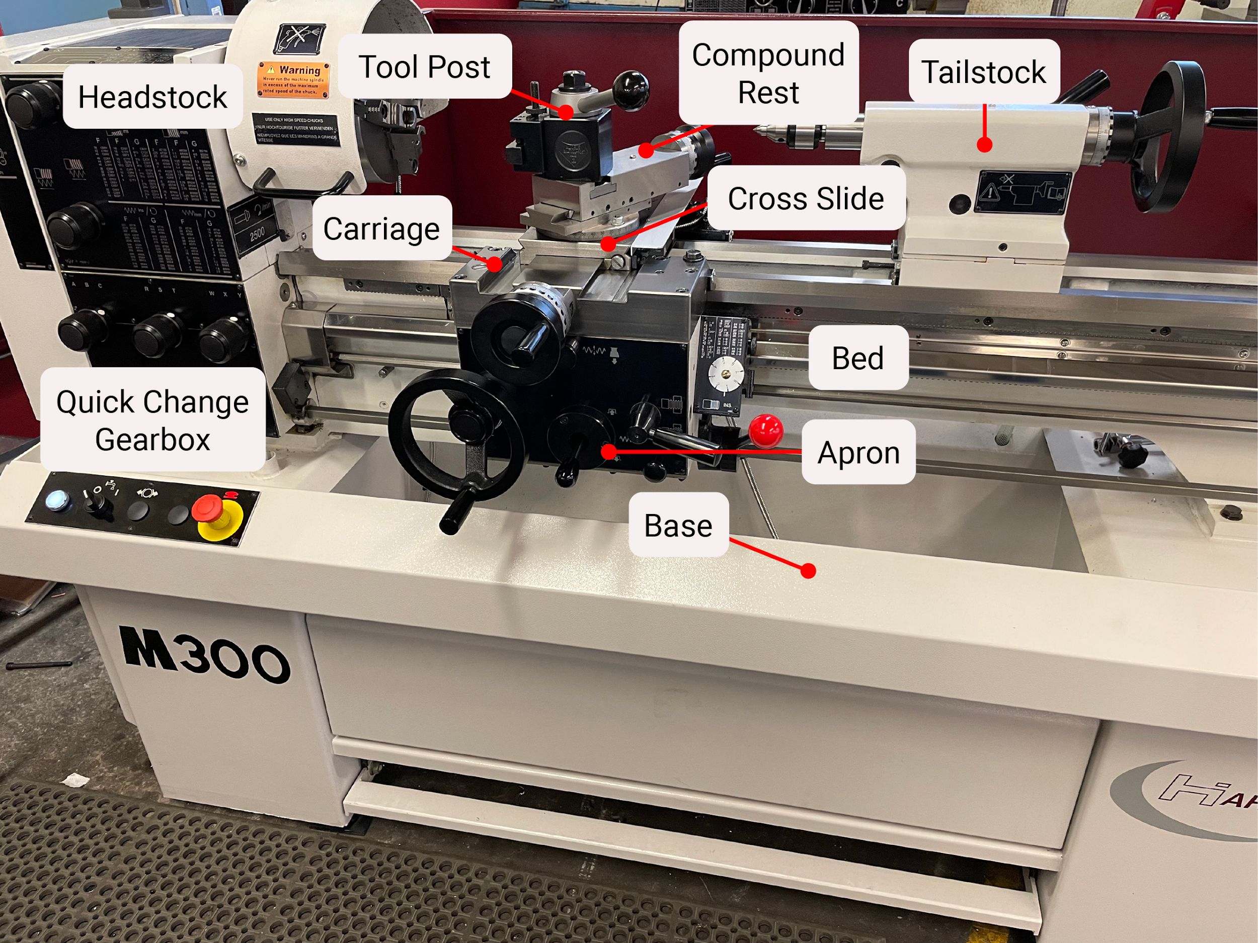
It is important that all lathe operators be familiar with the components of the machinery they are using. Getting to know the equipment features and functionality will help the machinist perform work in the safest and most efficient manner, as well as give them the industry-specific nomenclature necessary to effectively communicate with coworkers. One of the first things to consider when looking at a lathe is its size, or capacity. Lathes are sized by the diameter of work that can be turned, referred to as the swing, and the length of work that can be held between the spindle and tailstock. A common lathe size designation might be a 1340. This number designation means that a 13″ part can be turned over the bed, and it could be 40″ long in between the spindle and the tailstock.
Bed
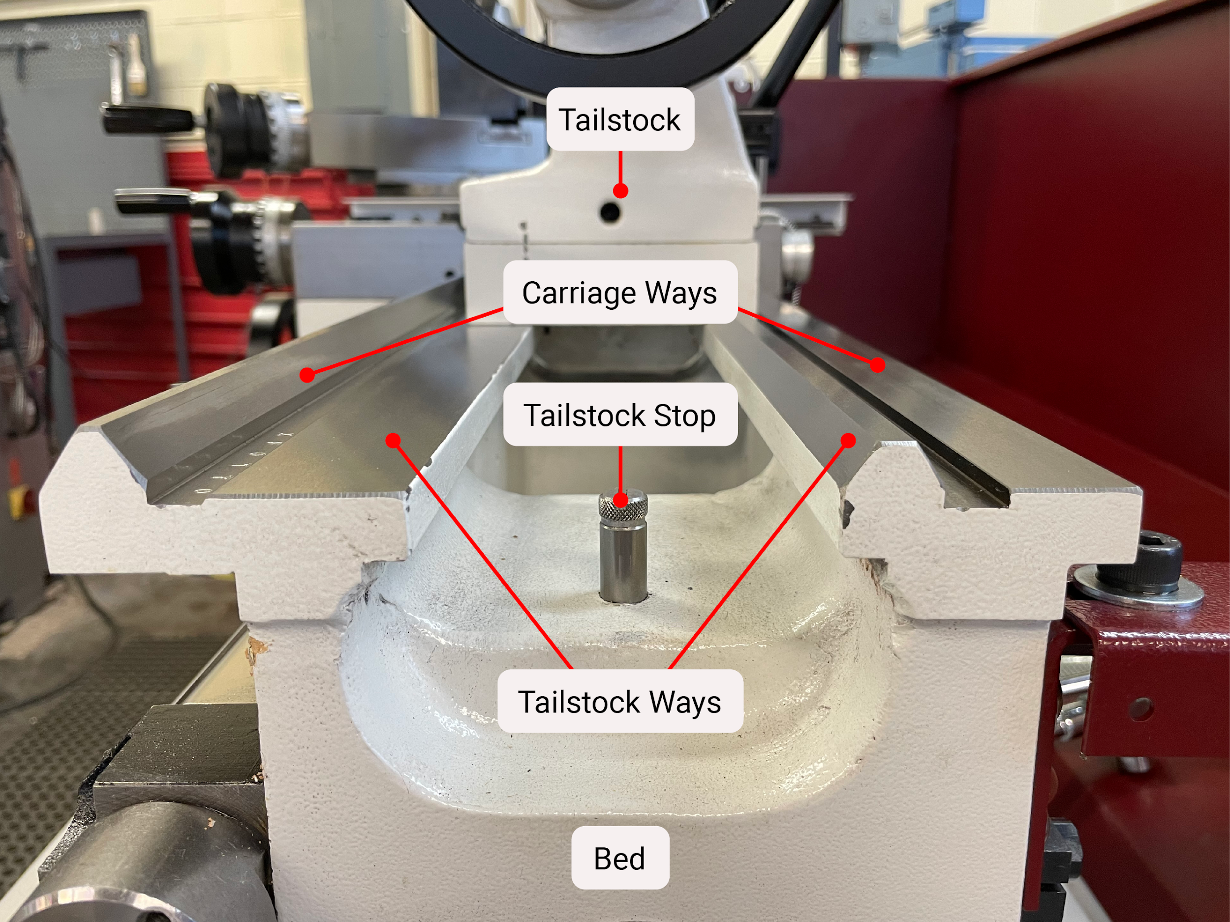
The bed is the main structural component of the lathe. It runs horizontally, and most other components are attached to it. The bed contains the ways of the machine. The ways are precision flat or angular surfaces that give the machine its accuracy. The components that drive the linear movement of the lathe sit on the ways. The bed also supports the feed rod and lead screw.
Headstock
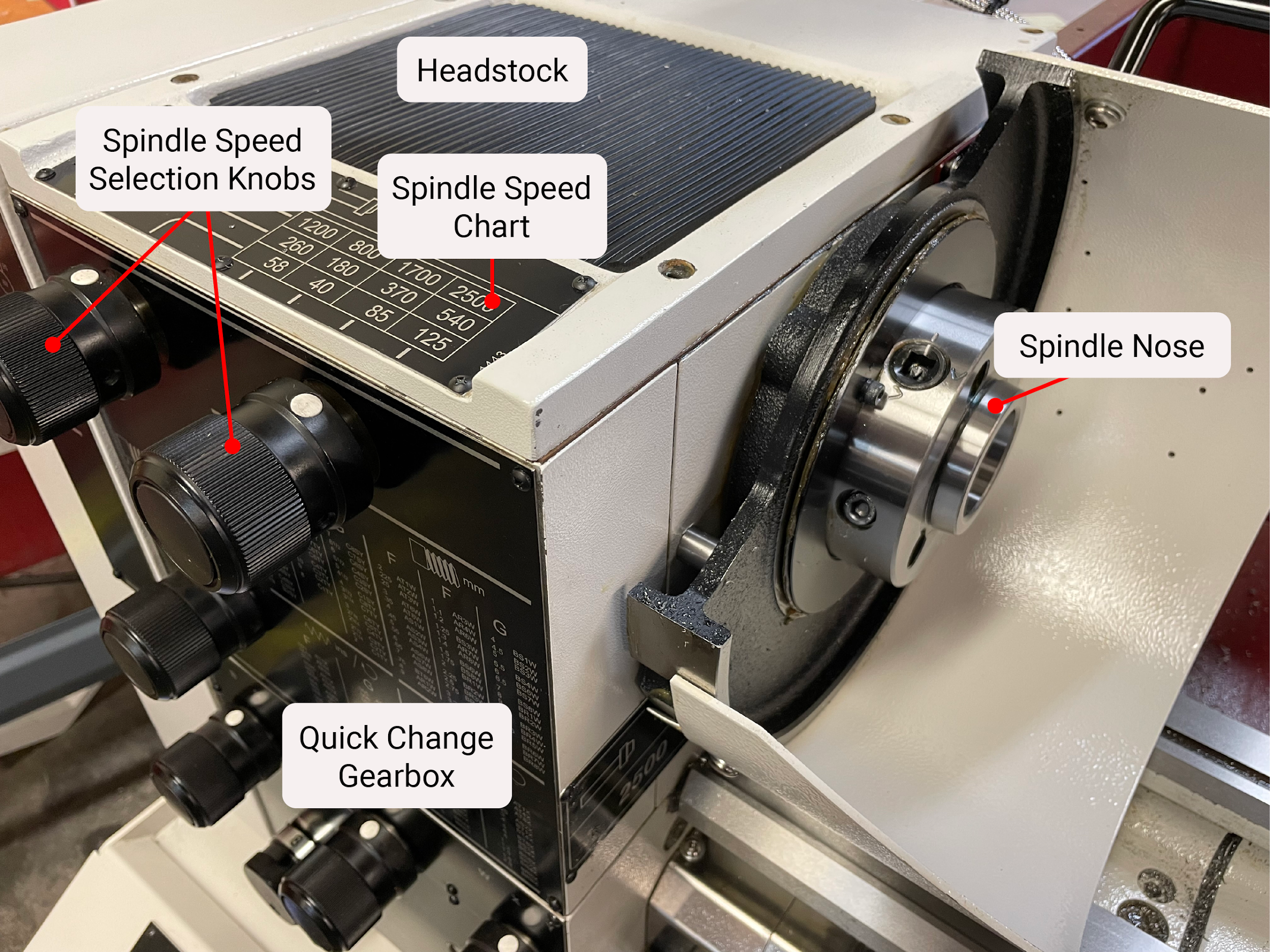
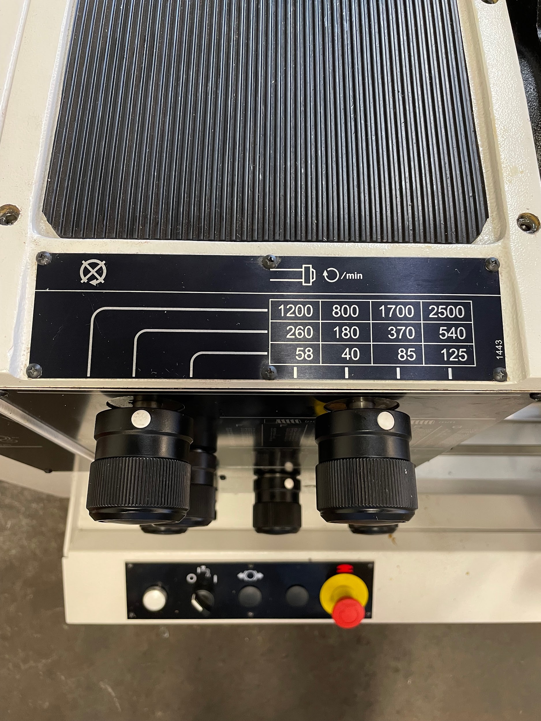
The headstock is attached to the left-hand side of the bed. It contains the motor, spindle, and all of the gearing required for machine speed changes. Some smaller machines may require the operator to change belt pulley positions or adjust a variable speed dial to alter speed. In the headstock, the spindle rotates on bearings.
Spindle
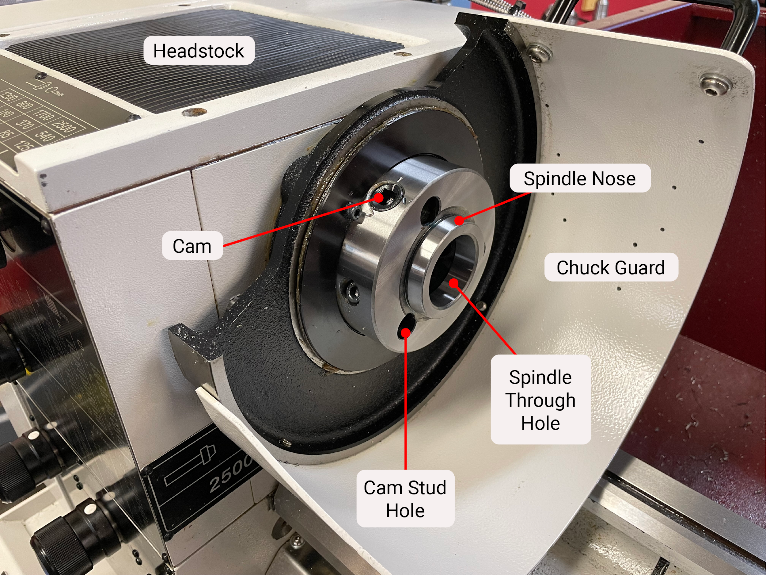
The spindle is located in the headstock and is driven by gears, shafts, belts, and pulleys attached to the motor. The nose of the spindle is where workholding devices are attached. Spindle speeds are generally altered by changing gears or occasionally by adjusting the power of a variable frequency drive. On latches equipped with power feed capabilities, the spindle will have gearing connected to it that provides power to the quick change gearbox, directly linking the two.
Motor
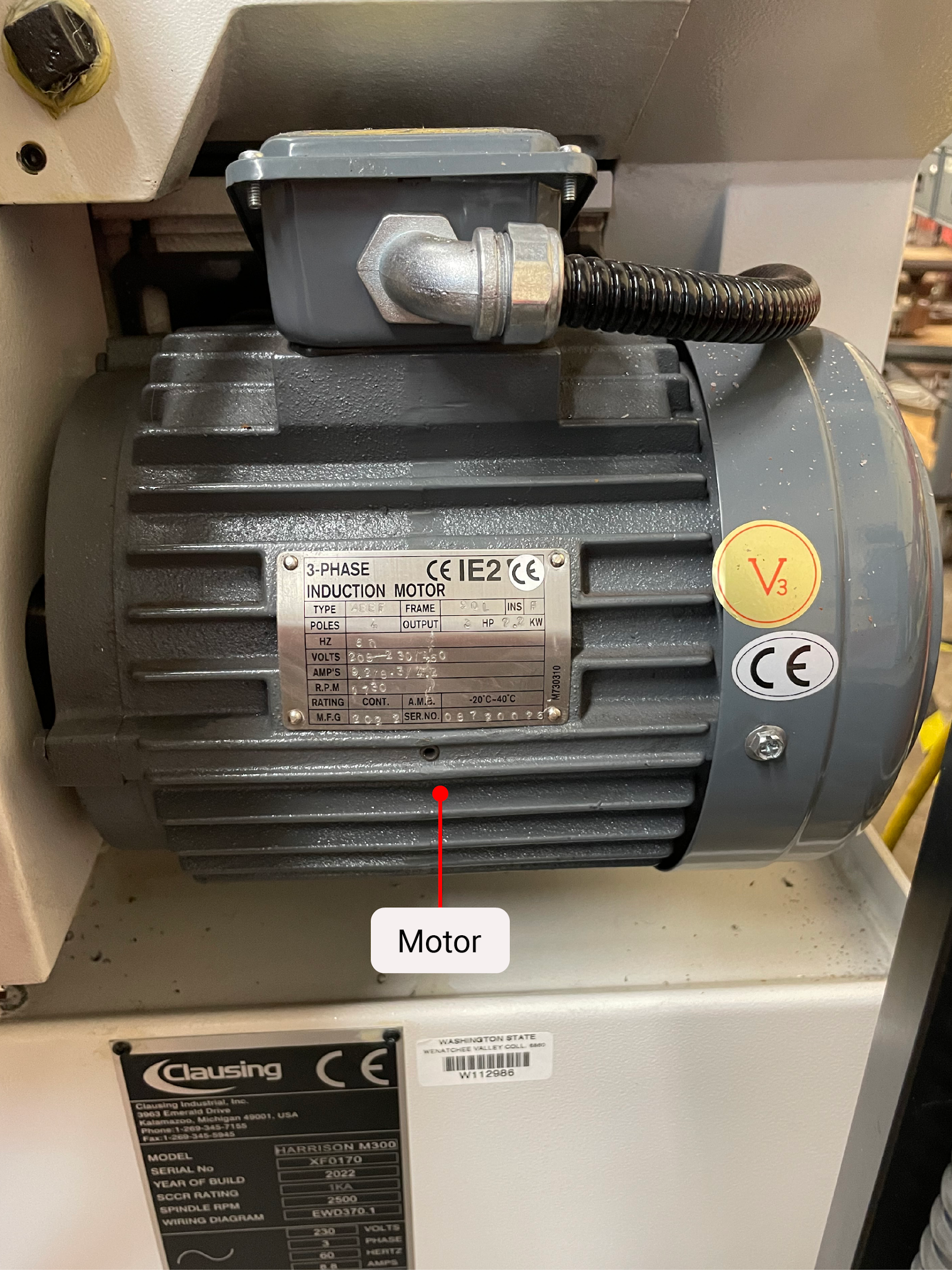
The motor is mounted to the backside of the lathe under the headstock. The motor has a pulley attached to it that is used to drive one or more belts to provide power to the lathe. Lathe motors come in different sizes, depending on the size and rigidity of the lathe. Industrial sized lathes often have 3 phase motors as opposed to the single-phase motors found on smaller hobby machines.
Gears
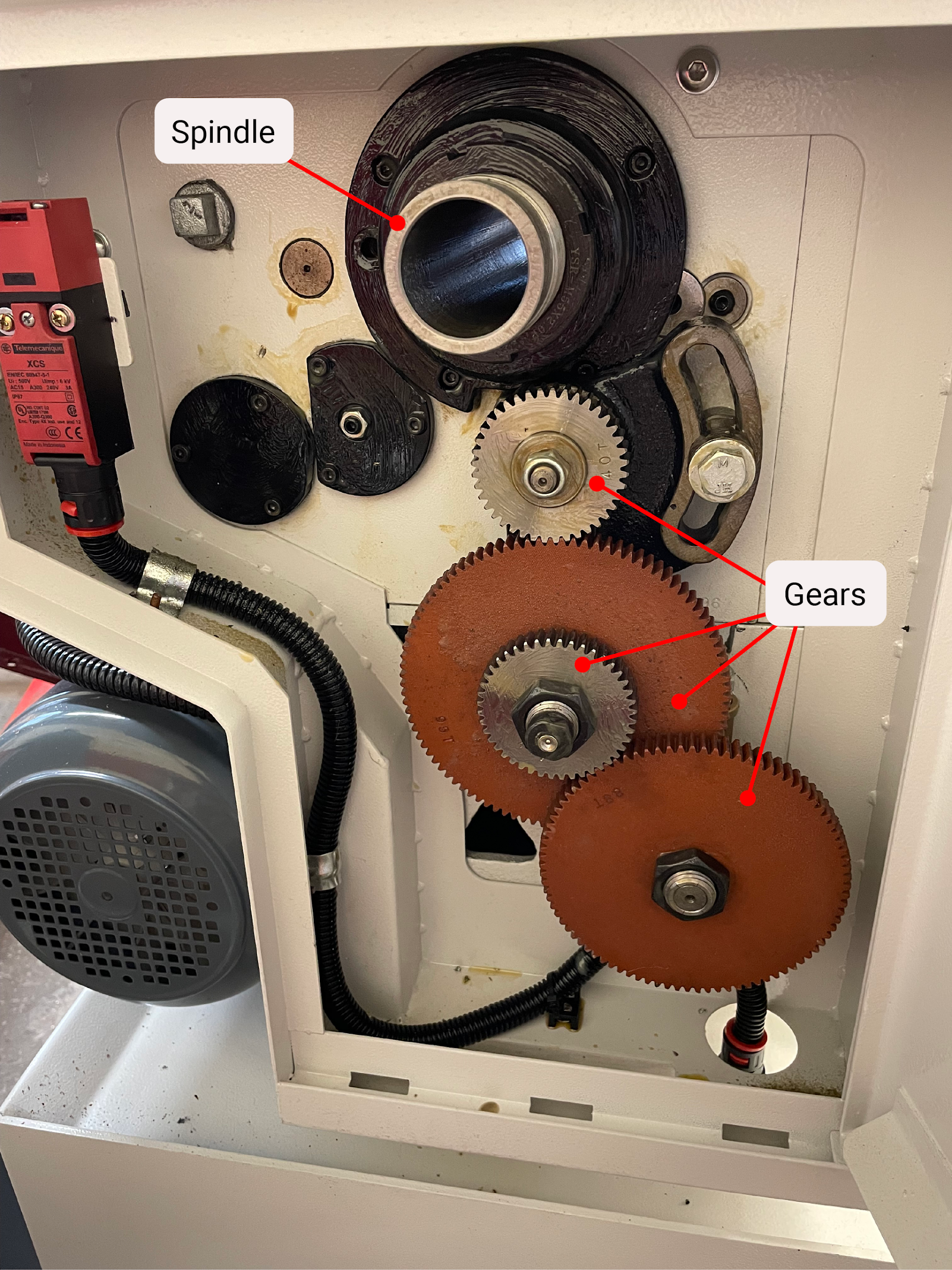
The gears of the lathe are found inside the headstock, inside the quick change gearbox, inside the apron, and as a way to connect the headstock to the quick change gearbox. Some smaller lathes may require the operator to manually change one or more gears between the headstock and the quick change gearbox in order to alter the range of feeds the lathe is capable of performing.
Carriage
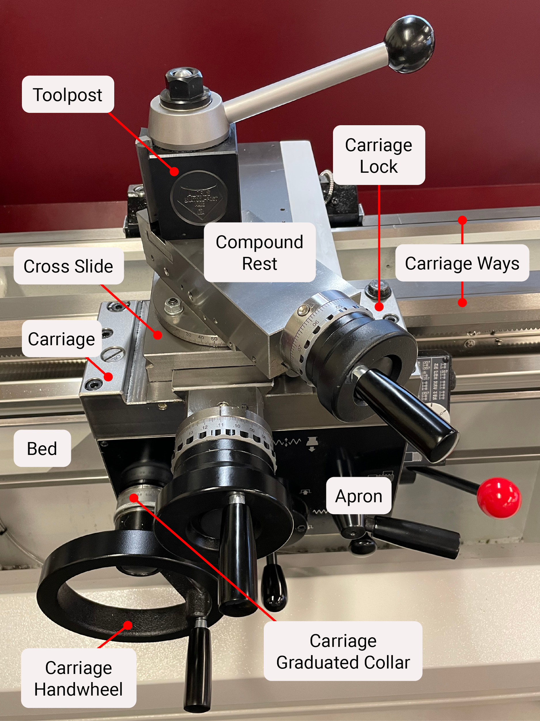
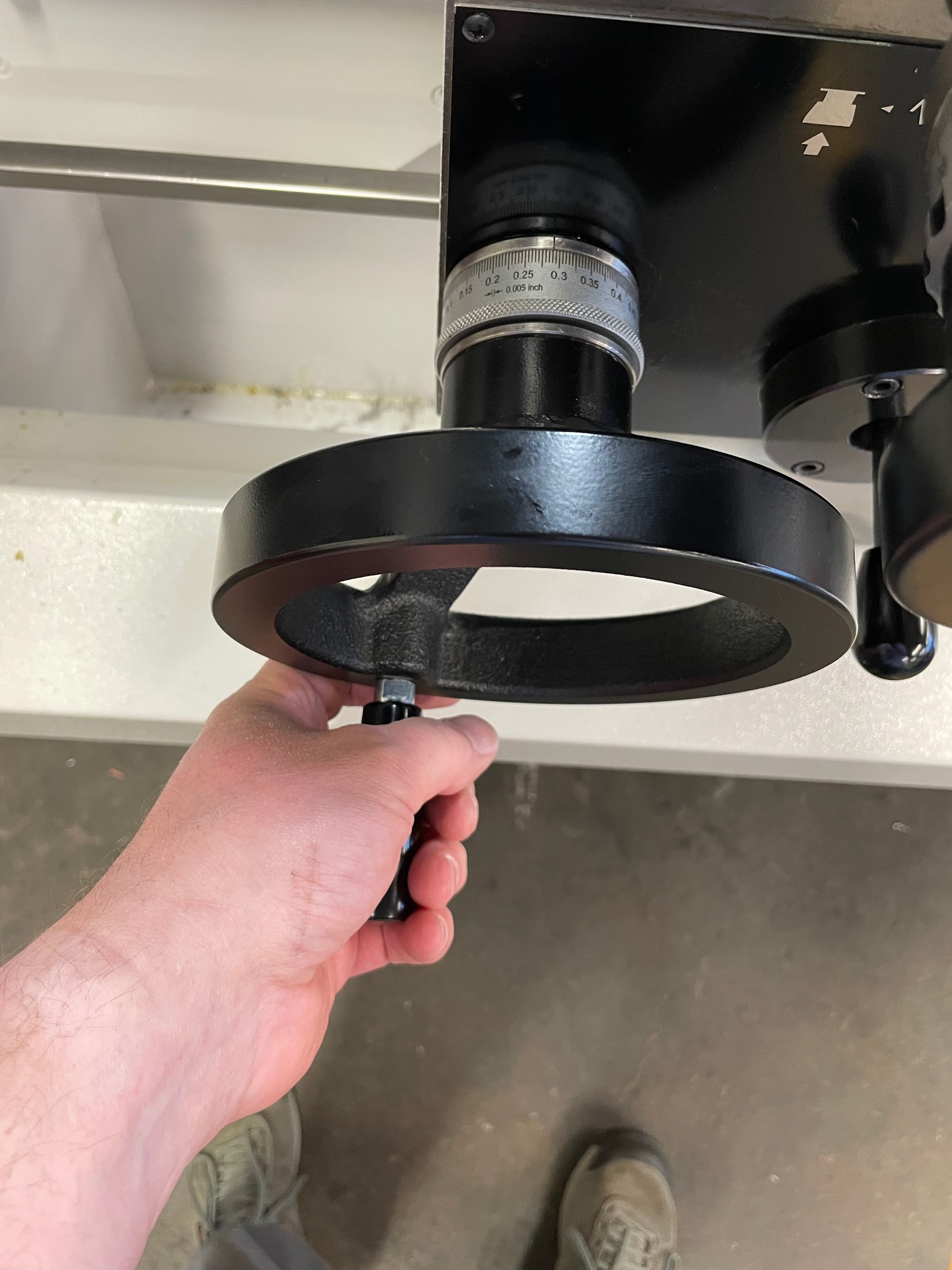
The carriage rides directly on the ways of the bed and is used to make axial movements of the lathe. The carriage supports both the cross slide and the compound rest. The carriage can have its movement locked to stabilize it during radial machining operations. The carriage handwheel is connected to gears that provide motion to the carriage by meshing with a rack gear mounted to the side of the bed. On imported lathes, the rack is often metric, making one full turn of the handwheel an uncommon length of measurement.
Often when machinists are moving machine components, they are thinking of making movements in three-dimensional space. The way the operator keeps track of the 3D movements is by using the Cartesian coordinate system. The carriage moves the tool left and right along the Z axis of the three-dimensional coordinate system.
Author’s Tip
Get to know and remember how many thousandths are in every rotation of your carriage handwheel. Each time I use a different lathe, that is one of the first things I look at. Knowing exactly what that distance is can sometimes mean the difference between making a good part and producing scrap.
Cross Slide
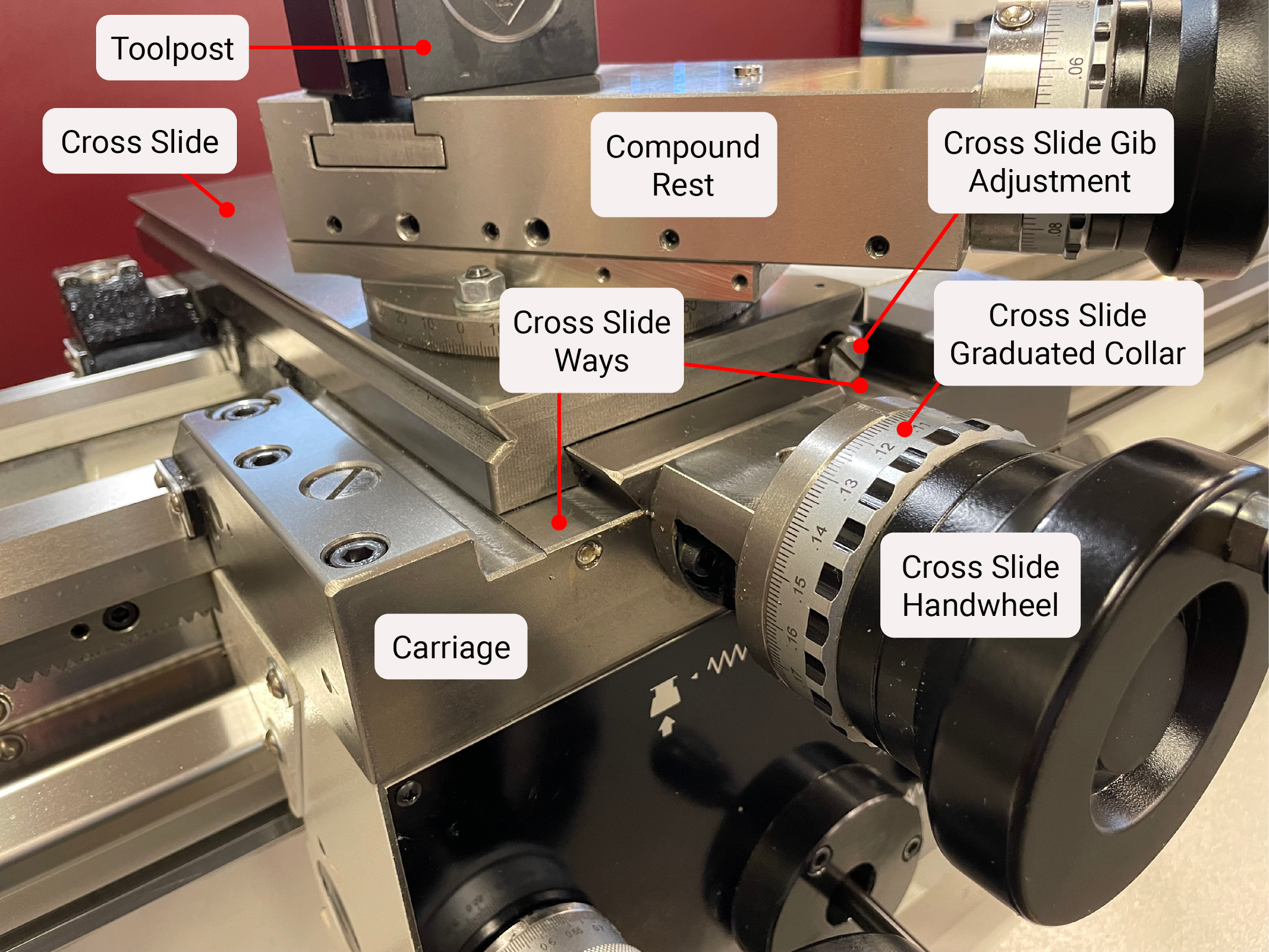
The cross slide is mounted on the carriage and is used to make radial movements on the lathe. The cross slide supports the compound rest that sits above it. The cross slide often has a lock on the side to stabilize it while making axial cuts. The cross slide handwheel turns a screw that provides .200 change in part diameter for each revolution. It is important to recognize that the graduations on this handwheel are a reflection of the amount to be removed from the part in diameter, and not a linear distance. The cross slide moves the part in and out along the X axis of the three-dimensional coordinate system.
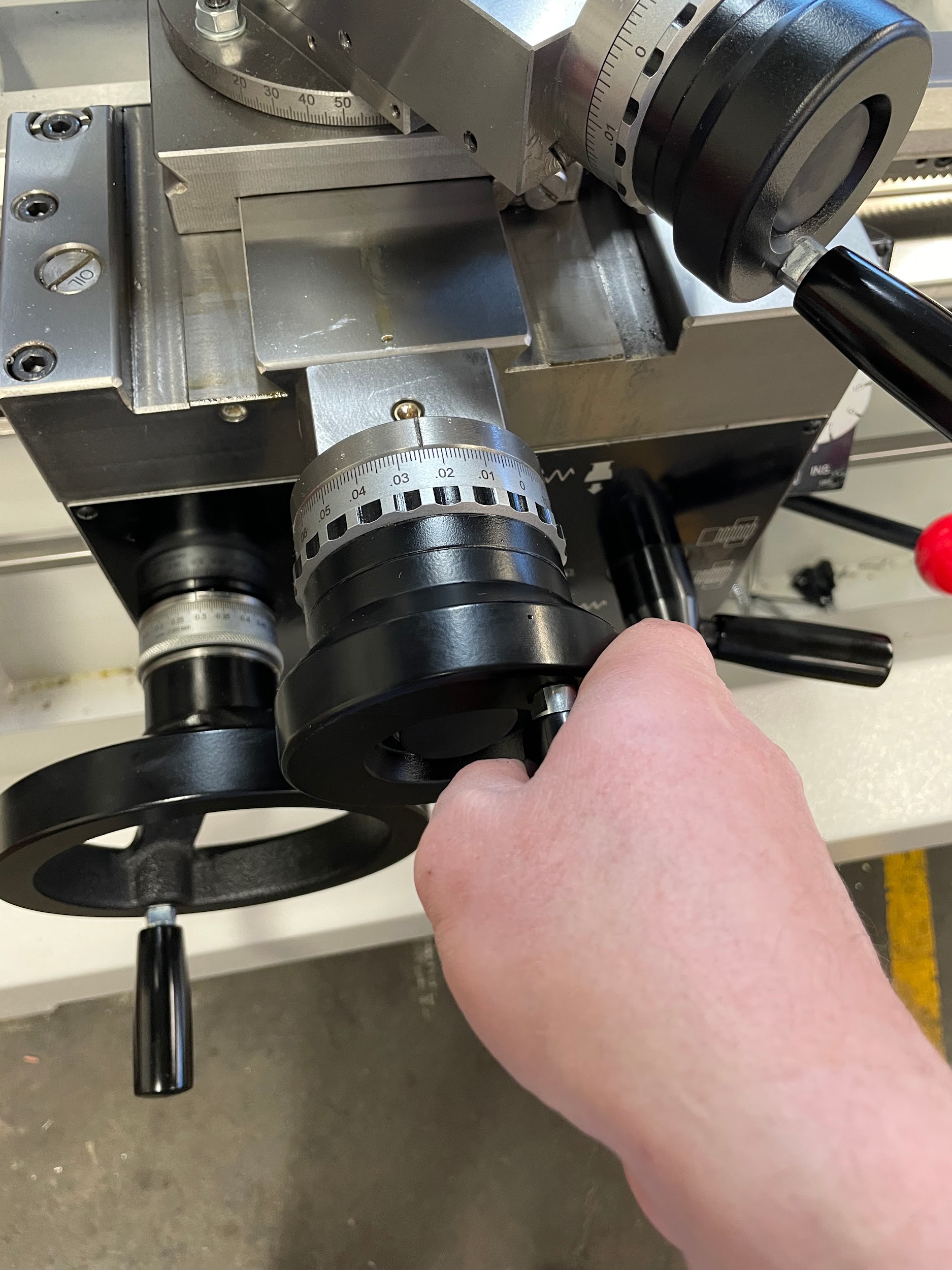
Compound Rest
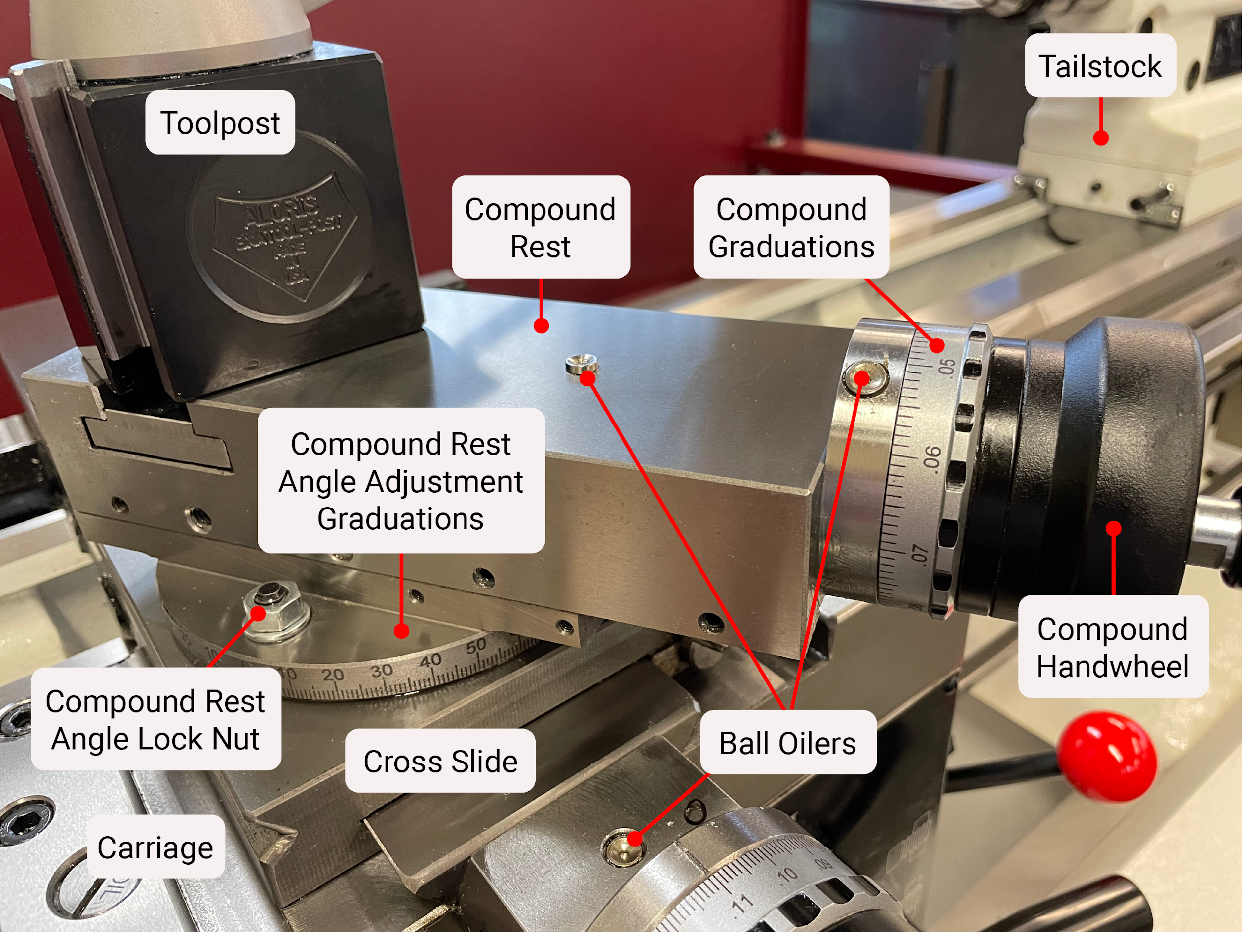
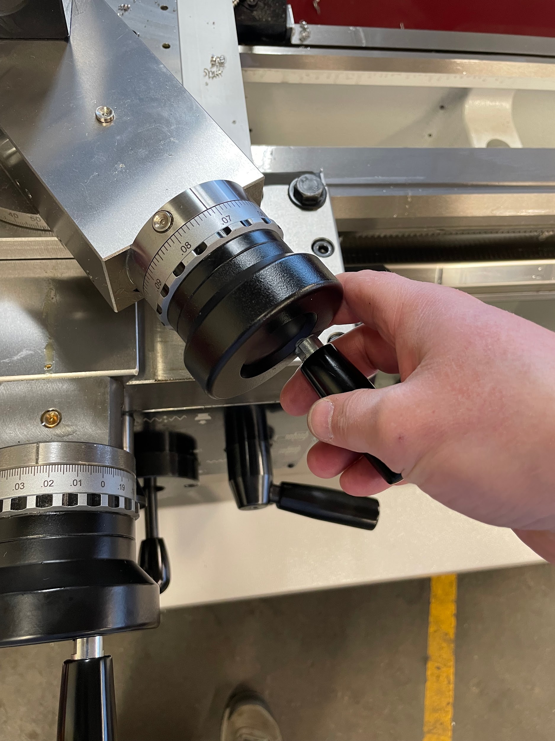
The compound rest is mounted on top of the cross slide and is used to make angular movements. The compound rest has a lock that is used to stabilize it when not in use. The handwheel of the compound rest turns a screw that creates .100 of linear movement for every revolution. Unlike the cross slide, the movement of compound is direct movement and not based on diameter.
Tool Post
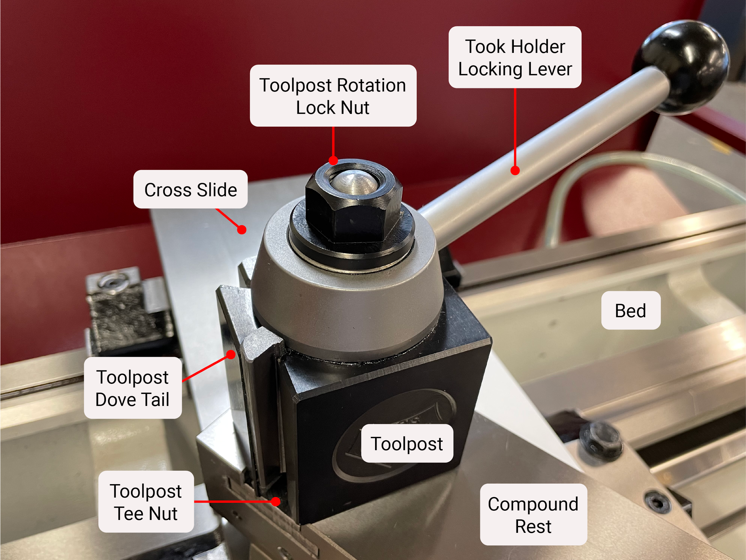
A tool post is used to secure the cutting tool. It is mounted on top of the compound rest by way of a single nut that tightens it in place. Tool posts come in many different styles; however, the quick-change toolpost is the modern standard in industry and is favored for its ease of use and adjustment.
Apron
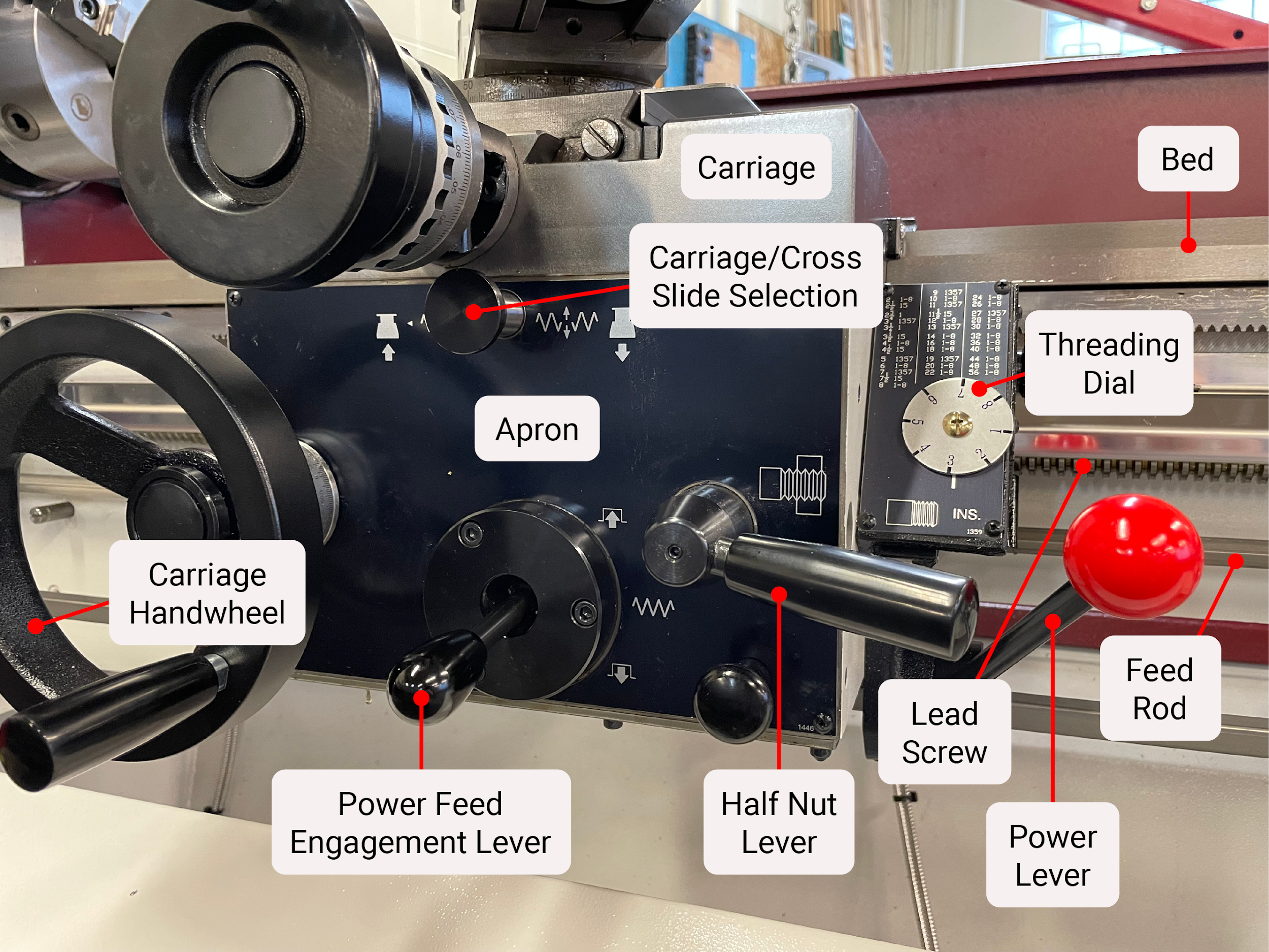
The apron is attached to the underside front of the carriage and houses the hand wheel for the carriage movement as well as the gearing for the power feed components. Attached to the front and side of the apron are many knobs and levers. These include the carriage handwheel, a lever to engage the carriage to the feed rod, the half nut lever to engage the garage to the lead screw, a threading dial for timing the start of threads, and the lever used to turn the lathe in forward and reverse.
Quick Change Gearbox
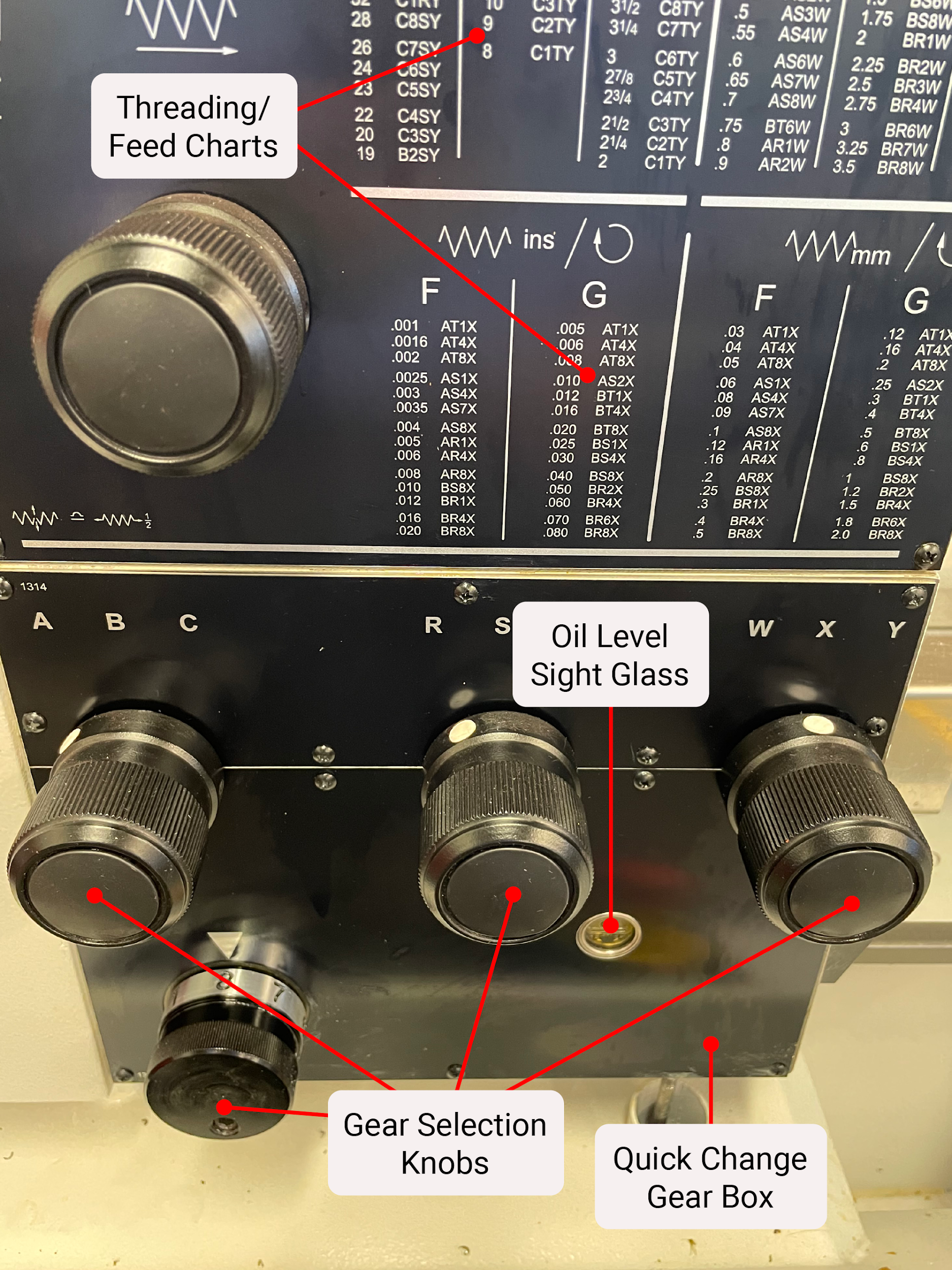
Most industrial-sized lathes are equipped with a quick change gearbox that is inside the casting just under the headstock. The gearbox is directly linked to the rotation of the spindle by a train of gears. The gearbox transmits the rotational movement of the spindle through the feed rod and lead screw for the power feed functions located in the apron.
Tailstock
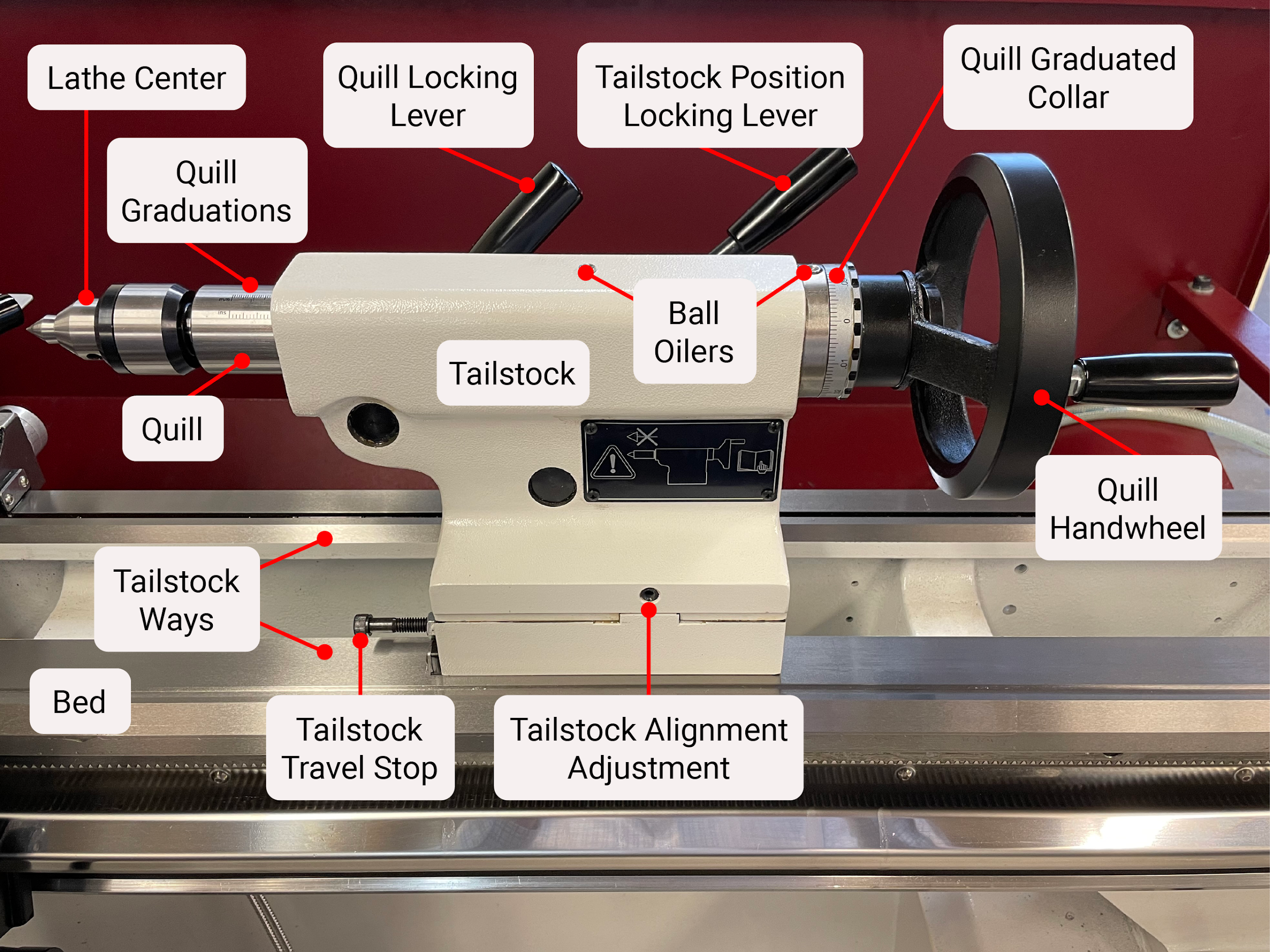
The tailstock is a movable component positioned on the right side of the lathe bed. It is used to perform all the standard hole making processes of a drill press, as well as adding extra support to long pieces of work. A handwheel moves the quill in and out to perform these actions. Depths of cut can be gauged by a simple scale on the quill or, more precisely, by graduations on the handwheel, often .100 in a revolution. It is easily slid along the bed on its own ways, and is secured in place using the locking lever in order to stabilize it during use. When the tailstock is used to support work, the quill can also be locked in place using the smaller locking lever, preventing it from retracting under pressure.
Digital Readout (DRO)
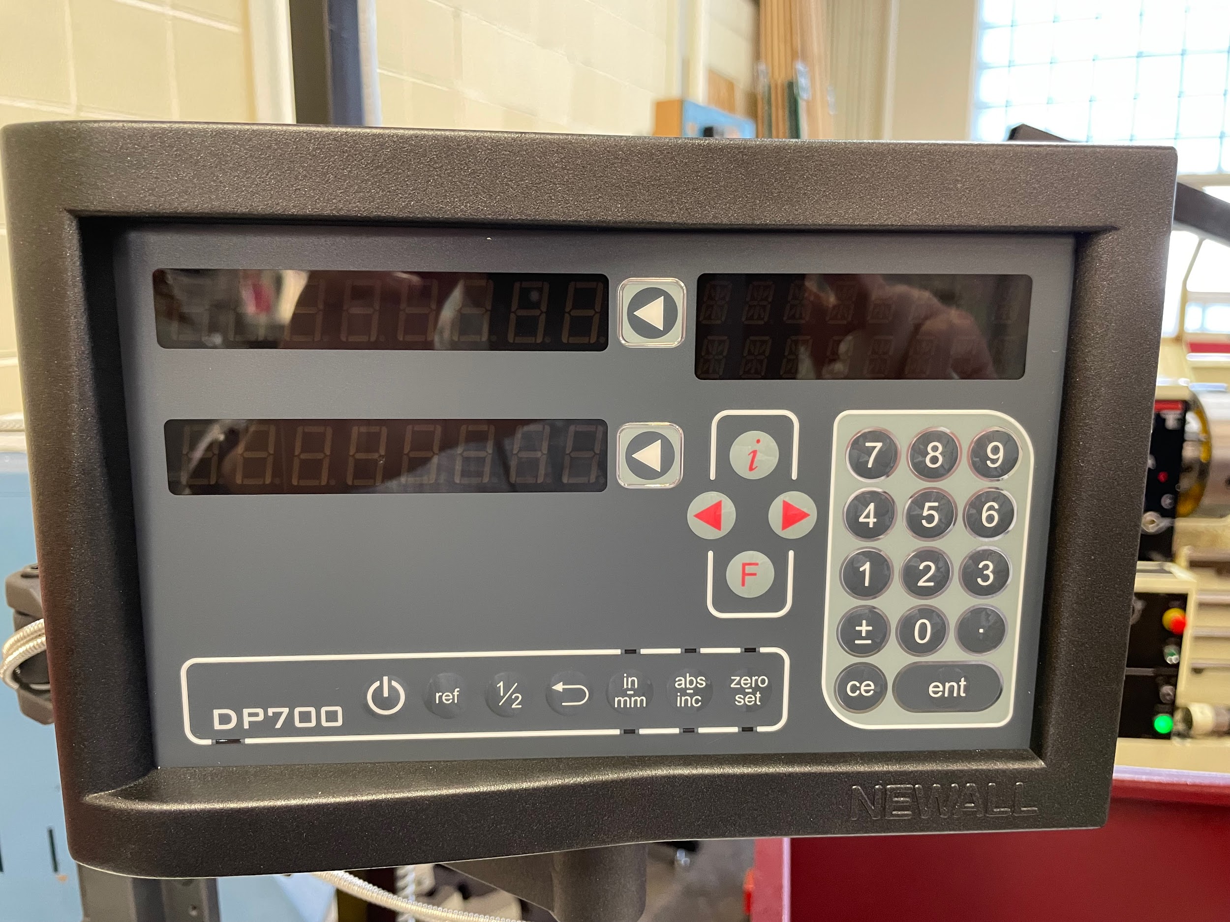
A digital readout (DRO) is a device that uses electronic scales to show the position of the machine digitally through a readout box. The DRO of a lathe keeps track of two axes. X is the in and out movement of the cross slide, and Z is the side to side motion of the carriage. X positive is defined as the direction away from the operator, and Z positive is to the right of the operator. The readout can be easily zeroed at the push of a button, basically performing the action of zeroing the handwheel collars. They can also be set to whatever value the operator needs. The DRO has a few advantages over the traditional graduated collars. These benefits include:
- The operator does not have to keep track of multiple rotations of the handwheel. On large projects it is easy to get lost. It is helpful to have the DRO keep track of all the operator’s movements.
- The readout doesn’t change unless the carriage or cross slide moves. This means that the task of considering backlash when changing cut directions is eliminated.
- DROs have a finer resolution than graduated collars. The collars of the cross slide are often .002 in diameter for each graduation. On the carriage, the collar is often graduated in .005 increments. Most DROs have a resolution of .0005 or smaller. This makes it much easier to hold tight tolerances.
Modern DROs can do many different efficiency tasks that will not be covered in this text. An operator should consult their DRO operator’s manual for full details.
One disadvantage of a DRO is the cost. They cost several thousand dollars to purchase and take hours to install. This is sometimes a larger cost than some smaller companies are able to incur. For this reason, all machinists should make sure they know how to operate equipment with graduated collars.
Attributions
- Figure 10.12: Labeled manual lathe by Micky R. Jennings, courtesy of Wenatchee Valley College, for WA Open ProfTech, © SBCTC, CC BY 4.0
- Figure 10.13: Lathe bed by Micky R. Jennings, courtesy of Wenatchee Valley College, for WA Open ProfTech, © SBCTC, CC BY 4.0
- Figure 10.14: Headstock by Micky R. Jennings, courtesy of Wenatchee Valley College, for WA Open ProfTech, © SBCTC, CC BY 4.0
- Figure 10.15: Spindle speeds by Micky R. Jennings, courtesy of Wenatchee Valley College, for WA Open ProfTech, © SBCTC, CC BY 4.0
- Figure 10.16: Spindle by Micky R. Jennings, courtesy of Wenatchee Valley College, for WA Open ProfTech, © SBCTC, CC BY 4.0
- Figure 10.17: Motor by Micky R. Jennings, courtesy of Wenatchee Valley College, for WA Open ProfTech, © SBCTC, CC BY 4.0
- Figure 10.18: Lathe gears by Micky R. Jennings, courtesy of Wenatchee Valley College, for WA Open ProfTech, © SBCTC, CC BY 4.0
- Figure 10.19: Carriage by Micky R. Jennings, courtesy of Wenatchee Valley College, for WA Open ProfTech, © SBCTC, CC BY 4.0
- Figure 10.20: Carriage handle by Micky R. Jennings, courtesy of Wenatchee Valley College, for WA Open ProfTech, © SBCTC, CC BY 4.0
- Figure 10.21: Cross slide by Micky R. Jennings, courtesy of Wenatchee Valley College, for WA Open ProfTech, © SBCTC, CC BY 4.0
- Figure 10.22: Cross slide by Micky R. Jennings, courtesy of Wenatchee Valley College, for WA Open ProfTech, © SBCTC, CC BY 4.0
- Figure 10.23: Compound rest by Micky R. Jennings, courtesy of Wenatchee Valley College, for WA Open ProfTech, © SBCTC, CC BY 4.0
- Figure 10.24: Compound rest handwheel by Micky R. Jennings, courtesy of Wenatchee Valley College, for WA Open ProfTech, © SBCTC, CC BY 4.0
- Figure 10.25: Quick change tool post by Micky R. Jennings, courtesy of Wenatchee Valley College, for WA Open ProfTech, © SBCTC, CC BY 4.0
- Figure 10.26: Apron by Micky R. Jennings, courtesy of Wenatchee Valley College, for WA Open ProfTech, © SBCTC, CC BY 4.0
- Figure 10.27: Quick change gearbox by Micky R. Jennings, courtesy of Wenatchee Valley College, for WA Open ProfTech, © SBCTC, CC BY 4.0
- Figure 10.28: Tailstock by Micky R. Jennings, courtesy of Wenatchee Valley College, for WA Open ProfTech, © SBCTC, CC BY 4.0
- Figure 10.29: Digital readout by Micky R. Jennings, courtesy of Wenatchee Valley College, for WA Open ProfTech, © SBCTC, CC BY 4.0
The maximum diameter that can be turned on a lathe.
A long structural component of a lathe that supports the other major components.The ways are on the top of the bed.
The precision metal surfaces that machine axes ride on.
The component at the far left of the lathe bed. It contains the spindle and the gears for speed changes.
The powered rotational component of a machine tool.
The component of a machine that provides the power for machining operations.
Mechanical components that transmit rotation and power.
The component of a lathe that attaches to the bed and provides an attachment point for the cross slide.
The component of a lathe that attaches to the carriage and provides an attachment point for the compound rest.
The component of a lathe that attaches to the cross slide and provides an attachment point for the tool post.
The component of a lathe that attaches to the compound rest and provides an attachment point for the cutting tools.
The component of a lathe that attaches to the underneath of the carriage and houses the mechanisms for power feeding.
A rod that transmits power from the quick change gearbox to the apron for power feeding purposes.
A lever that engages the apron with the lead screw during threading operations.
An acme screw that transmits power from the quick change gearbox to the apron for threading purposes.
A device that allows the operator to precisely time the engagement of the half nut lever during threading operations.
An internal gearbox that contains a combination of gears necessary for power feed operations on a lathe.
A support component that is used to hold the end of the work with a center when turning long flexible workpieces. Also used for performing hole making operations.
The telescoping component on machine tools that allows for easy hole making procedures.
