10.7 Tooling
Micky R. Jennings
Tooling refers to the tools used on machinery to cut parts. Lathes use some unique tools that are generally seen only in turning work. On the lathe, the work is the part that rotates, and the tooling is held stationary. When the tooling is fed into the revolving work, it removes material creating a round shape.
Cutting Tool Materials
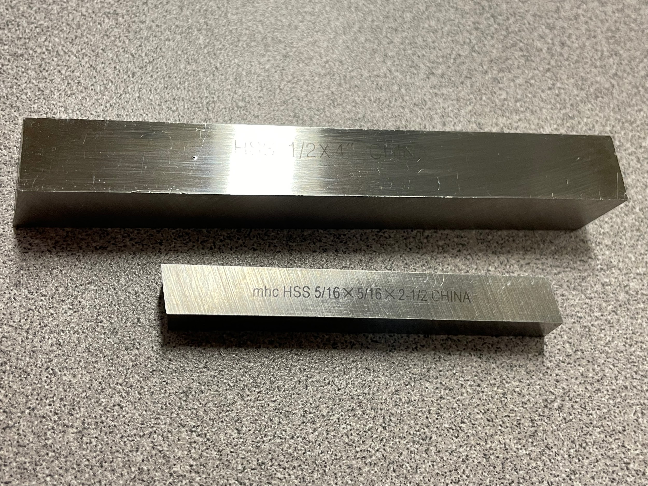
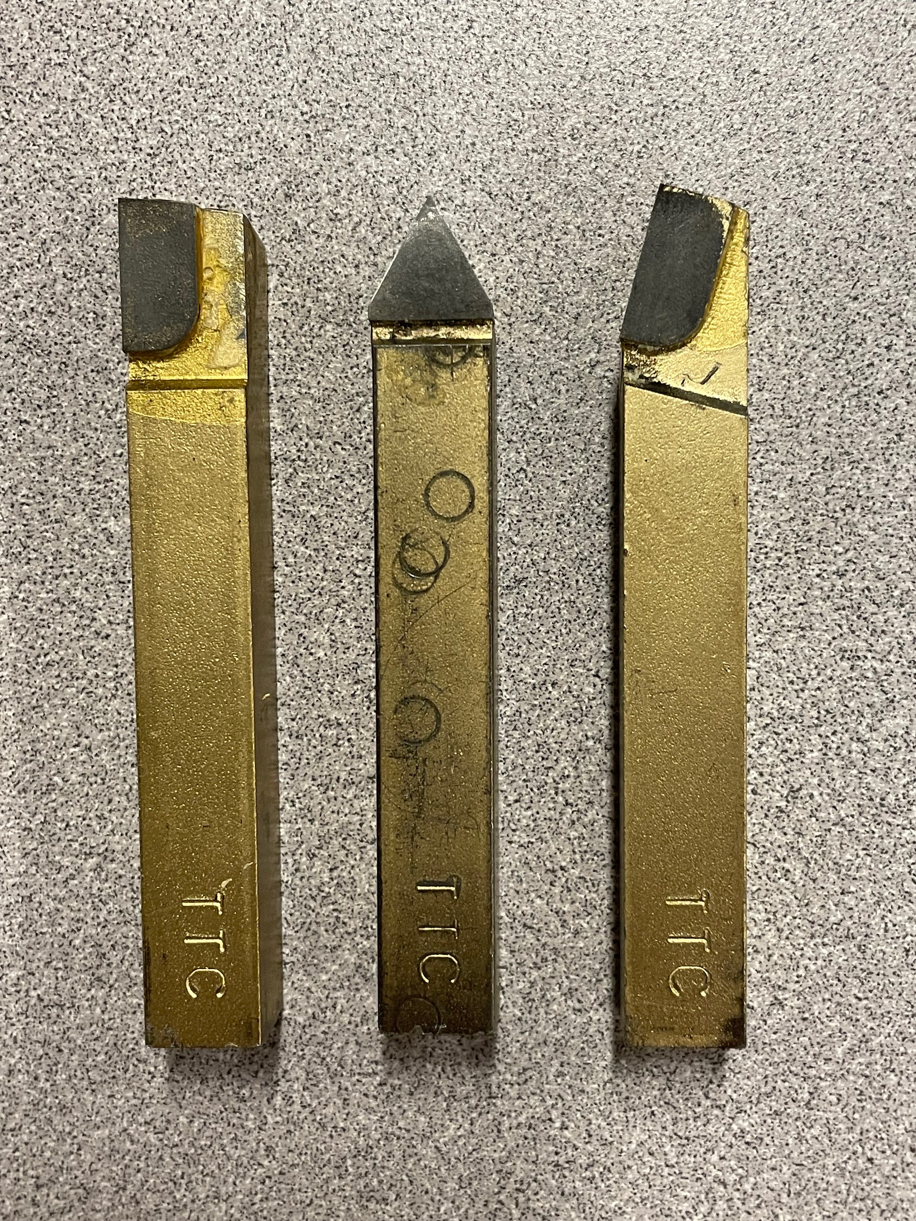
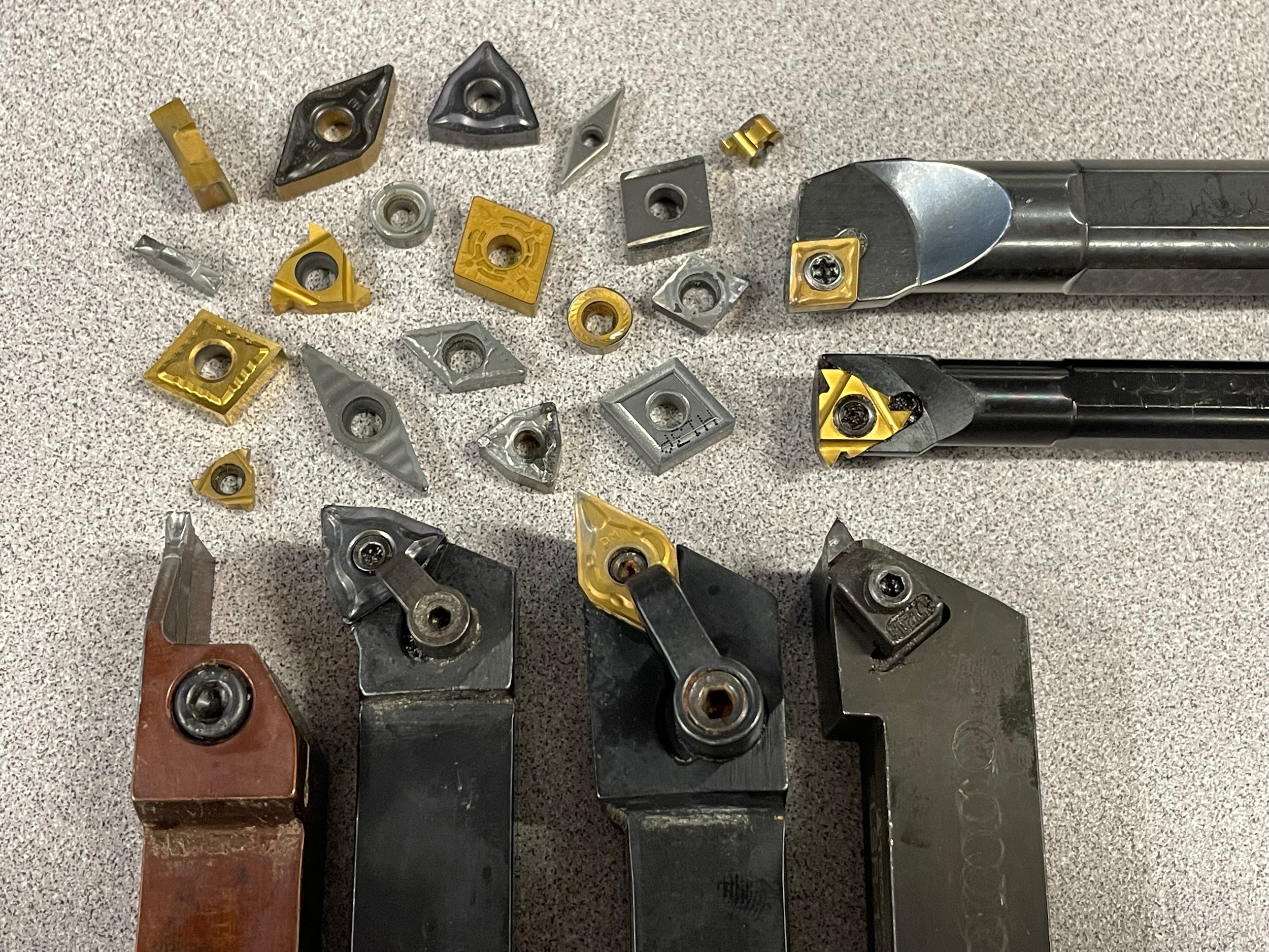
Turning tools can be made of many different materials such as high speed steel (HSS), cobalt, brazed carbide, cermet, diamond, and ceramic. However, the most common in the machining industry is the carbide indexable insert. Carbide inserts come in many shapes, styles, compositions, and coatings. In the examples given in this text, HSS will serve as a baseline, and the carbide inserts will be uncoated and general purpose.
Facing/Turning Tools
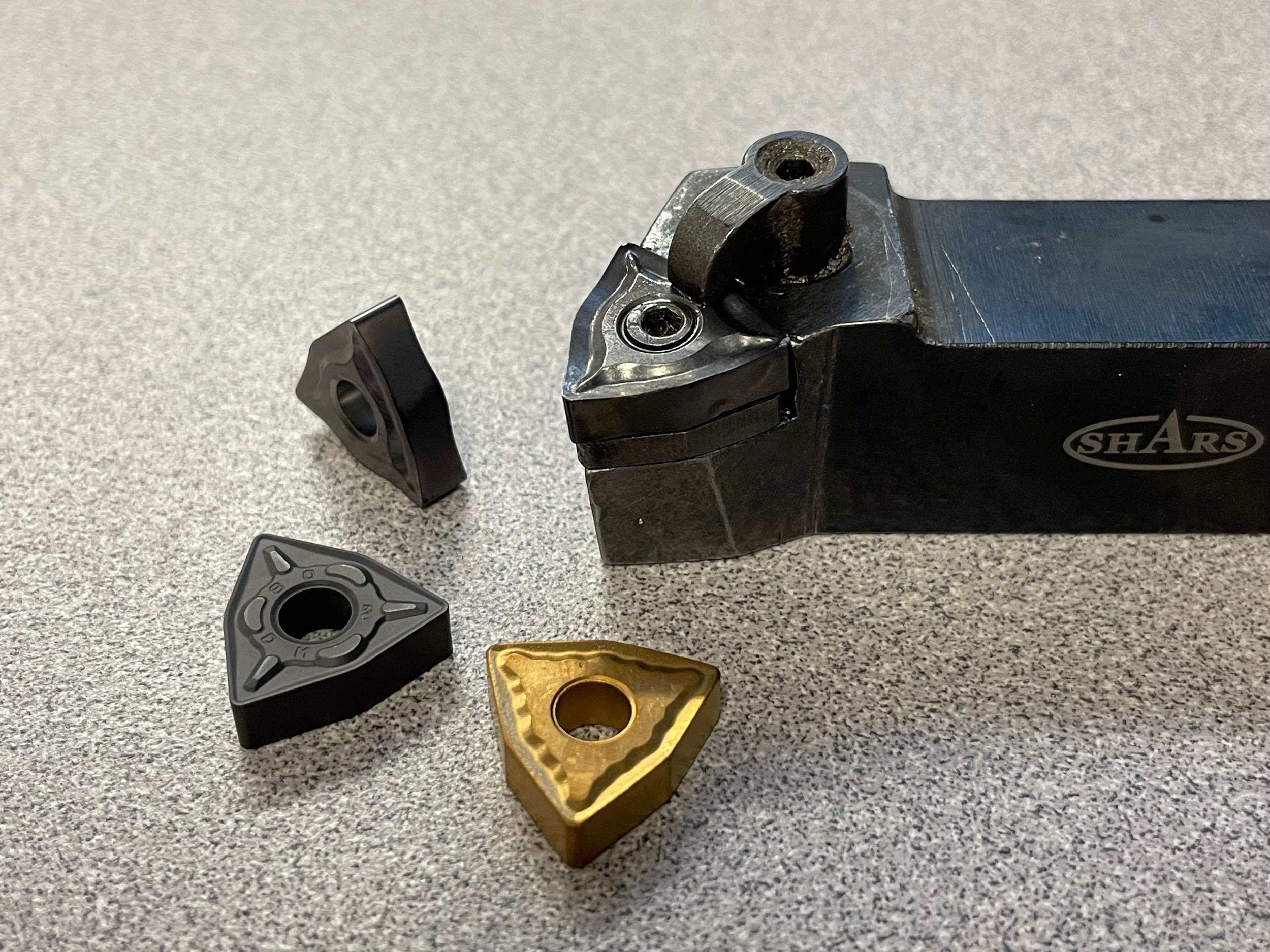
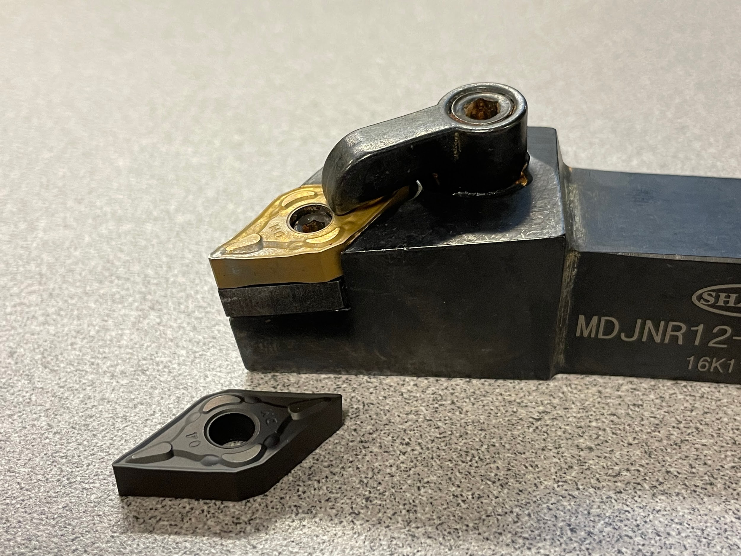
General purpose facing and turning tools come in different shapes and sizes. First, there are right hand tools, and there are left hand tools. Right hand tools are designed to cut from right to left and left hand tools are designed to cut from left to right. A few basic tool shapes are the 80 degree, the 55 degree, and the 35 degree turning tool. When used as intended, an 80 degree holder has 5 degrees of clearance when facing and 5 degrees of clearance when turning. When used this way, both operations can be completed with the same tool without rotating the tool to achieve clearance.
Grooving Tools
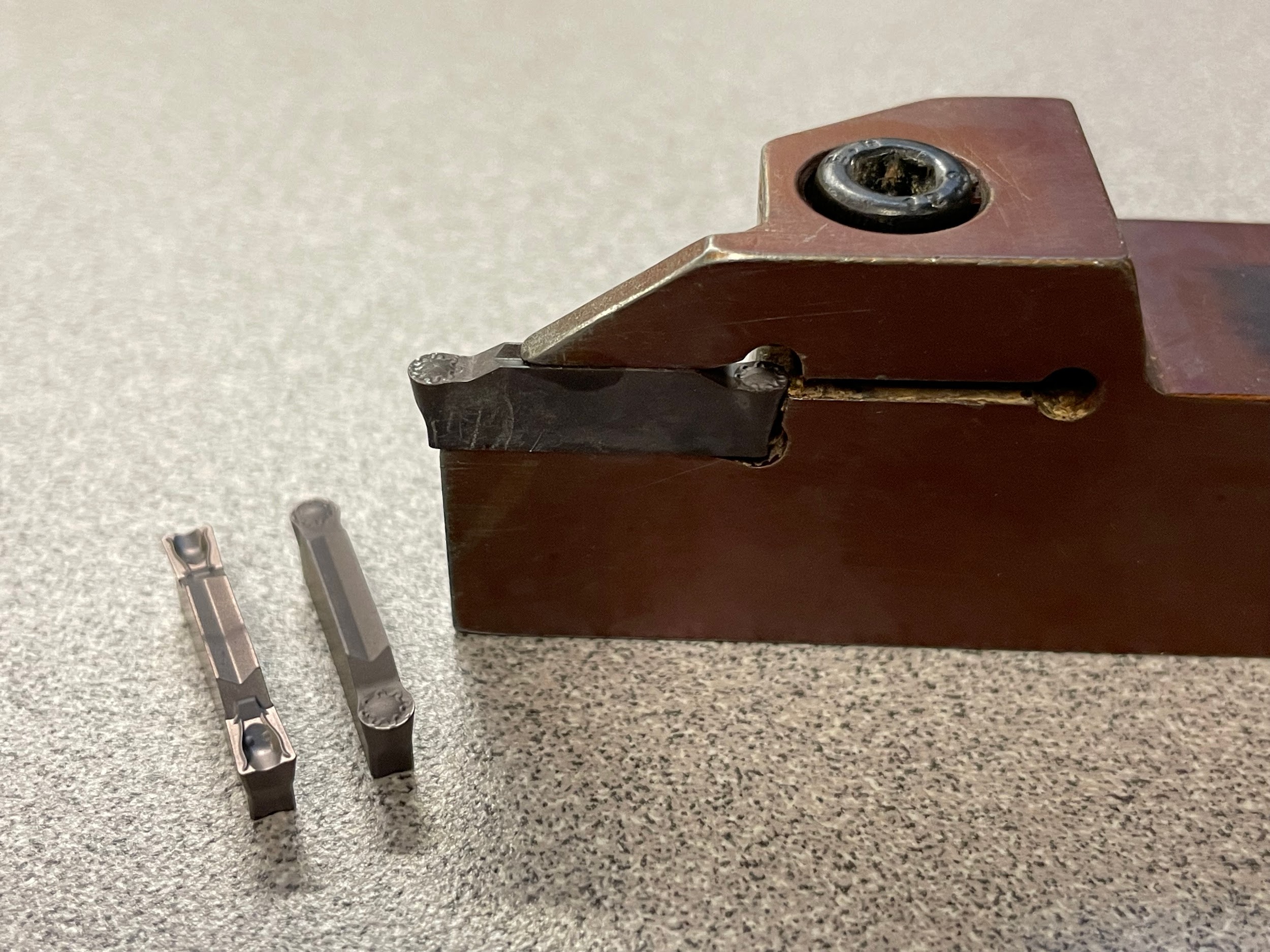
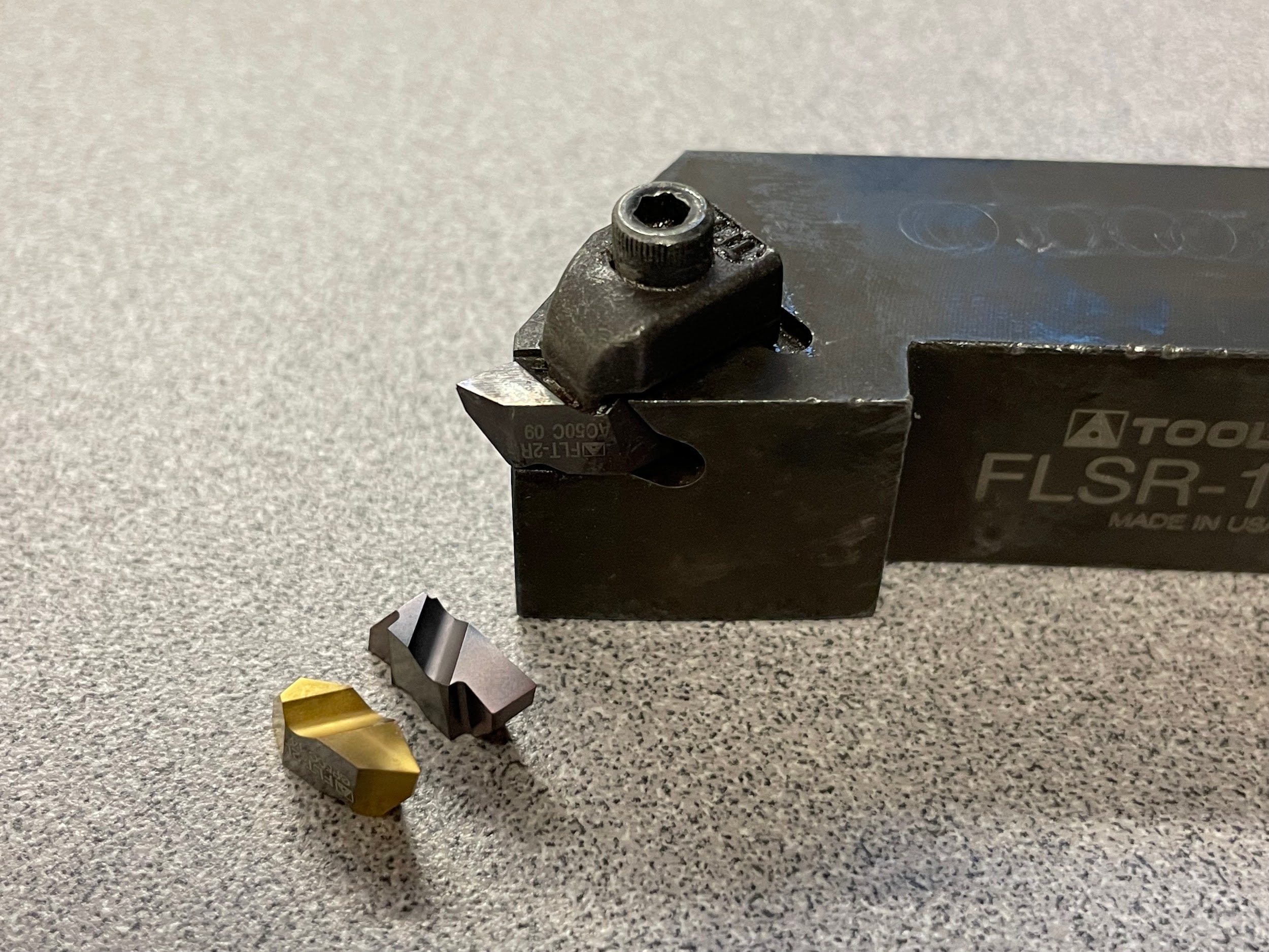
Grooving tools used to create grooves or shapes on the outside diameter of the workpiece. A grooving insert can be many different shapes and sizes and the insert holder may be designed to hold a variety of insert shapes. When the groove shape isn’t standard, a grooving tool may be used to profile the shape. Modern grooving tools are also generally carbide inserts of various shapes and sizes. Some are not only designed for standard radial plunges, but also light axial turning.
Threading Tools
Threading tools on a lathe are also most often made of carbide and are in insert form. These tools are used to create threads on parts larger than the standard taps and dies a machinist may have for thread creation. Often, a threading tool will utilize the same tool holder as a grooving tool.
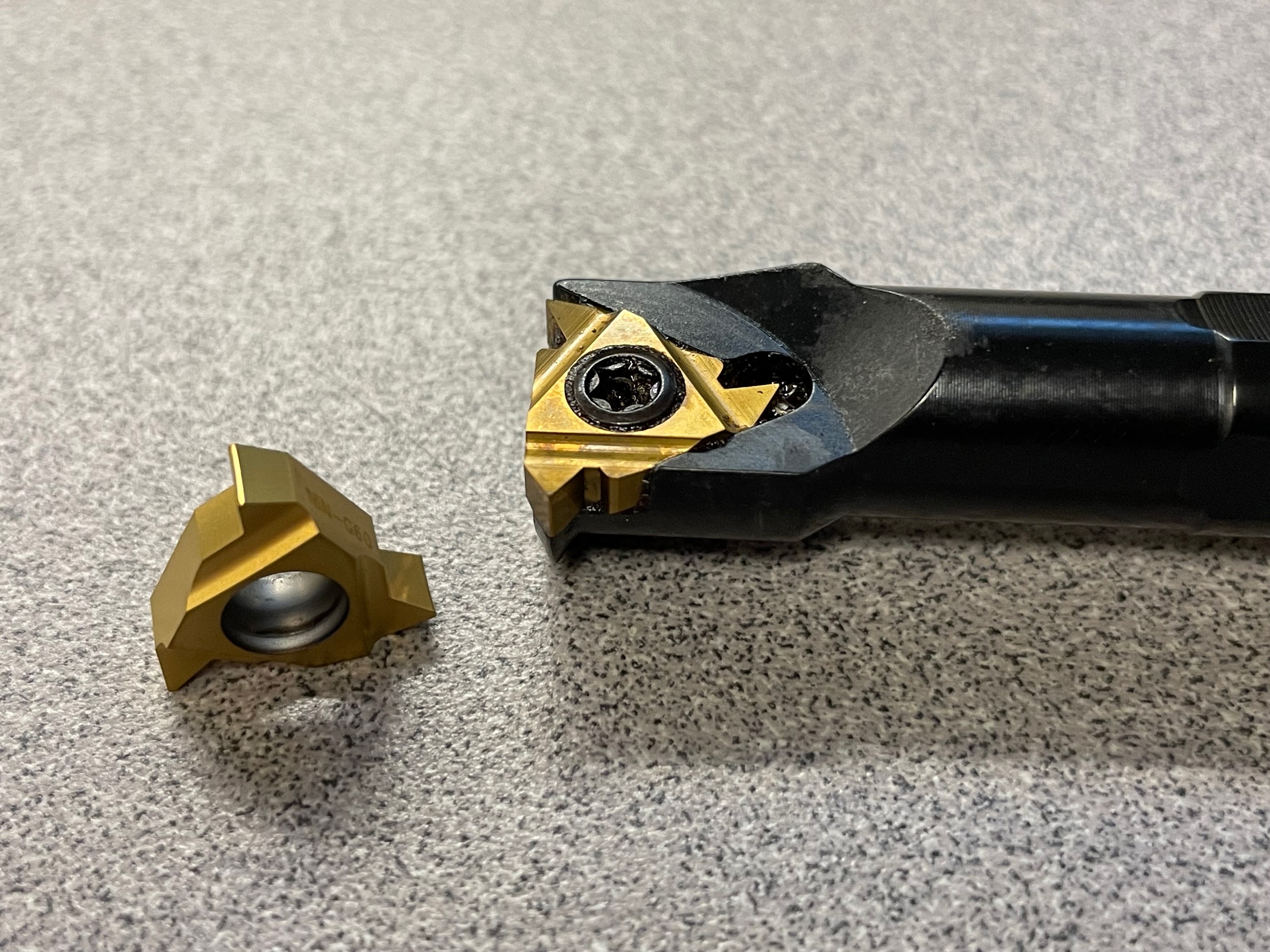
Boring Bars
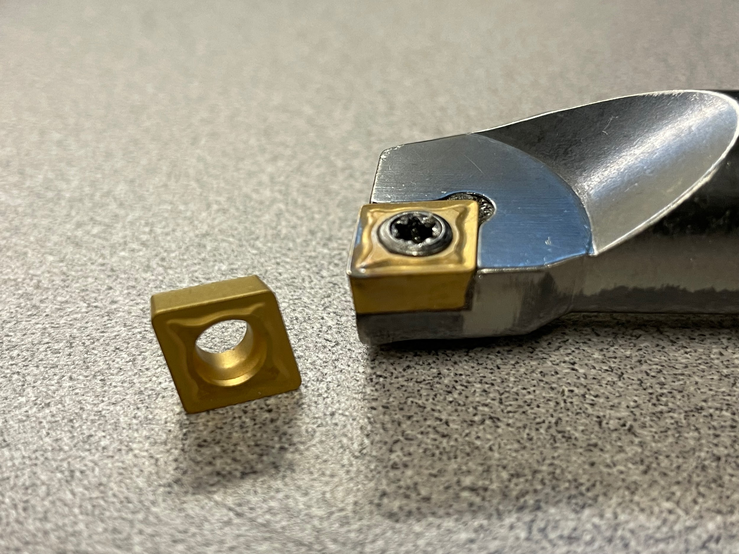
Boring bars on a lathe have a similar function to turning and facing tools except they are used on the inside of the part. An insert is attached to a rigid bar that hangs out in front of the tool post and is fed inside an existing hoe to enlarge it or create other features. Boring bars come in many different sizes and lengths.
Grooving Bars
Grooving bars are similar in construction to a boring bar, but instead of increasing the size and shape of an existing hole, they are used to create grooves inside a hole. An “O” ring seal is a good example of this.
Threading Bars
Threading bars are similar in construction to a boring bar, but instead of increasing the size and shape of an existing hole, they are used to create threads inside a hole. Threading bars are used when the size of the required thread is too large to be easily tapped.
Part-off Blades
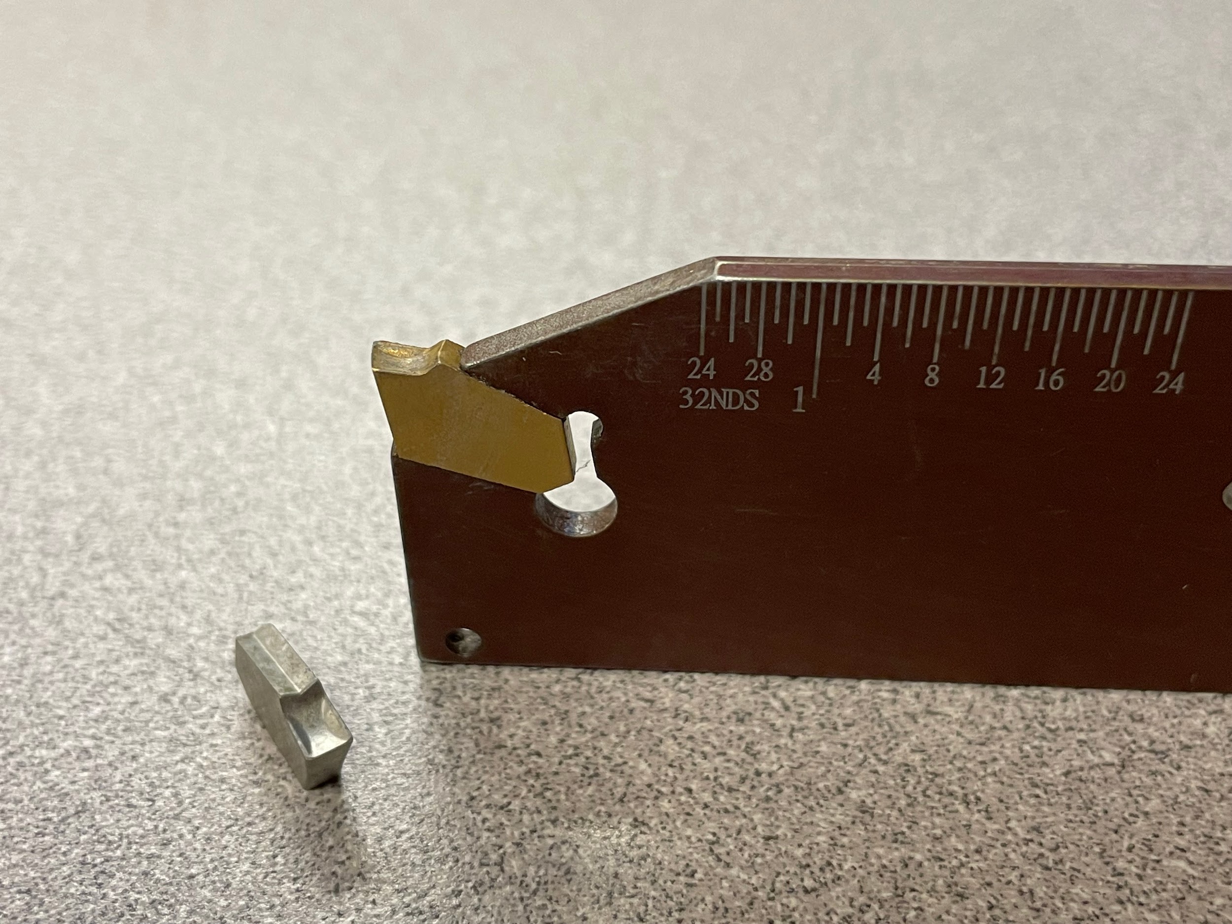
A modern part-off blade also employs carbide inserts. However, on manual machines, HSS part-off blades are still widely used for their durability. The part-off blade is designed to cut a finished part off from a piece of bar stock held in the lathe chuck.
Form Tools
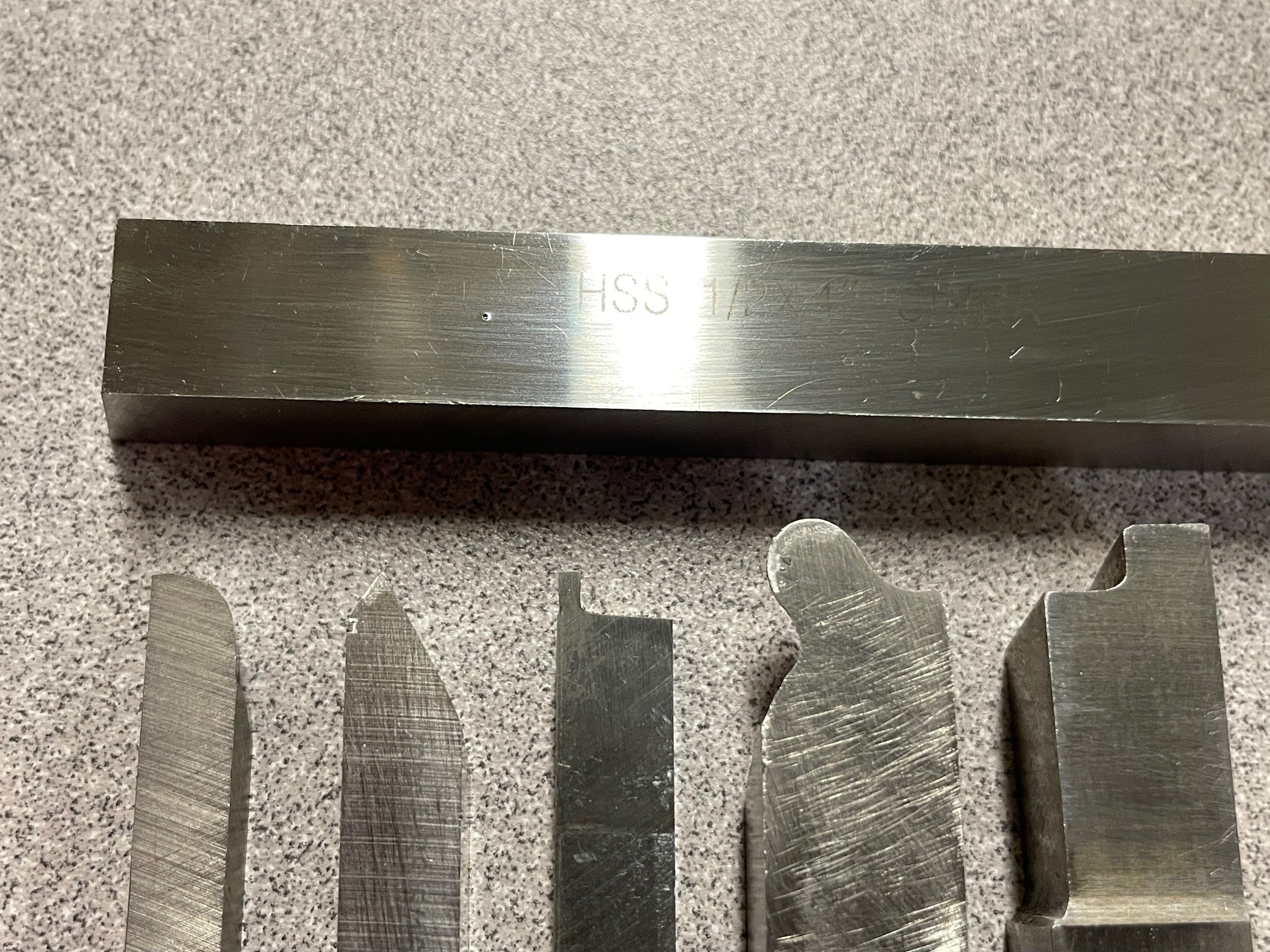
Form tools are often specialty tools created with the exact shape of a part’s feature on the tool. The tool is used in a straight plunging motion and the feature required is generated without further tool manipulation. Form tools can be made of any material, but on manual equipment, HSS is a good option. On manual lathes, tooling like this may be created because the feature desired is too difficult to make with standard tooling. A form tool generally has a larger cutting edge than a standard tool and will probably require a slower spindle speed to help eliminate the possibility of chatter.
Knurling Tools
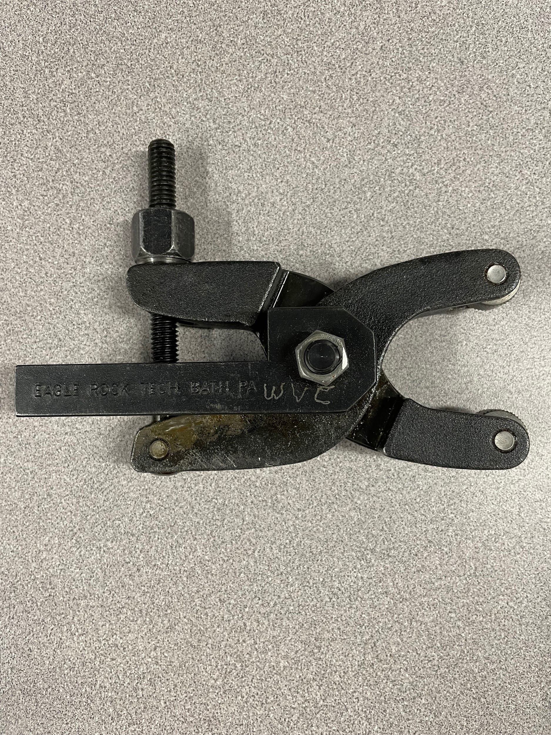
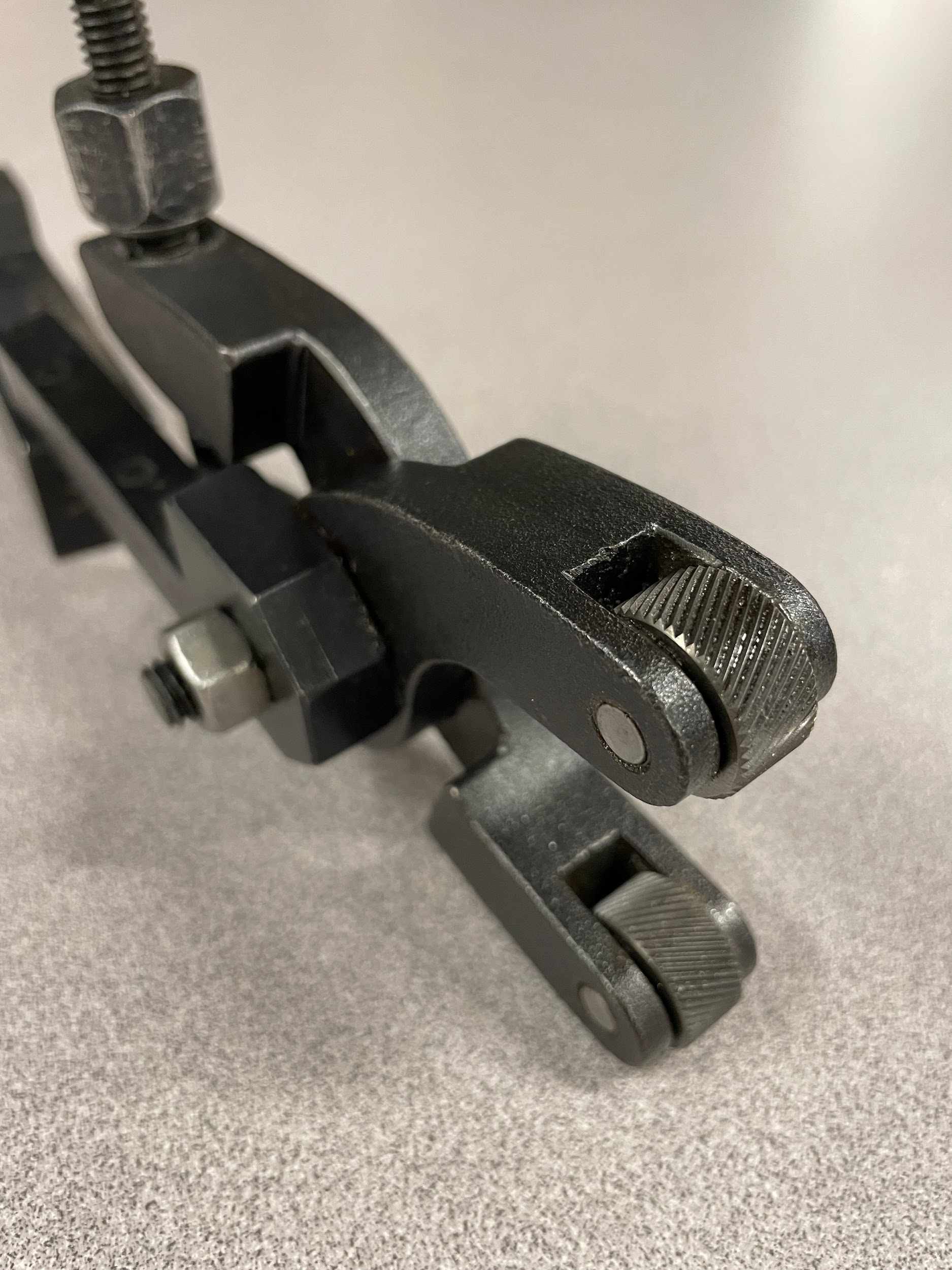
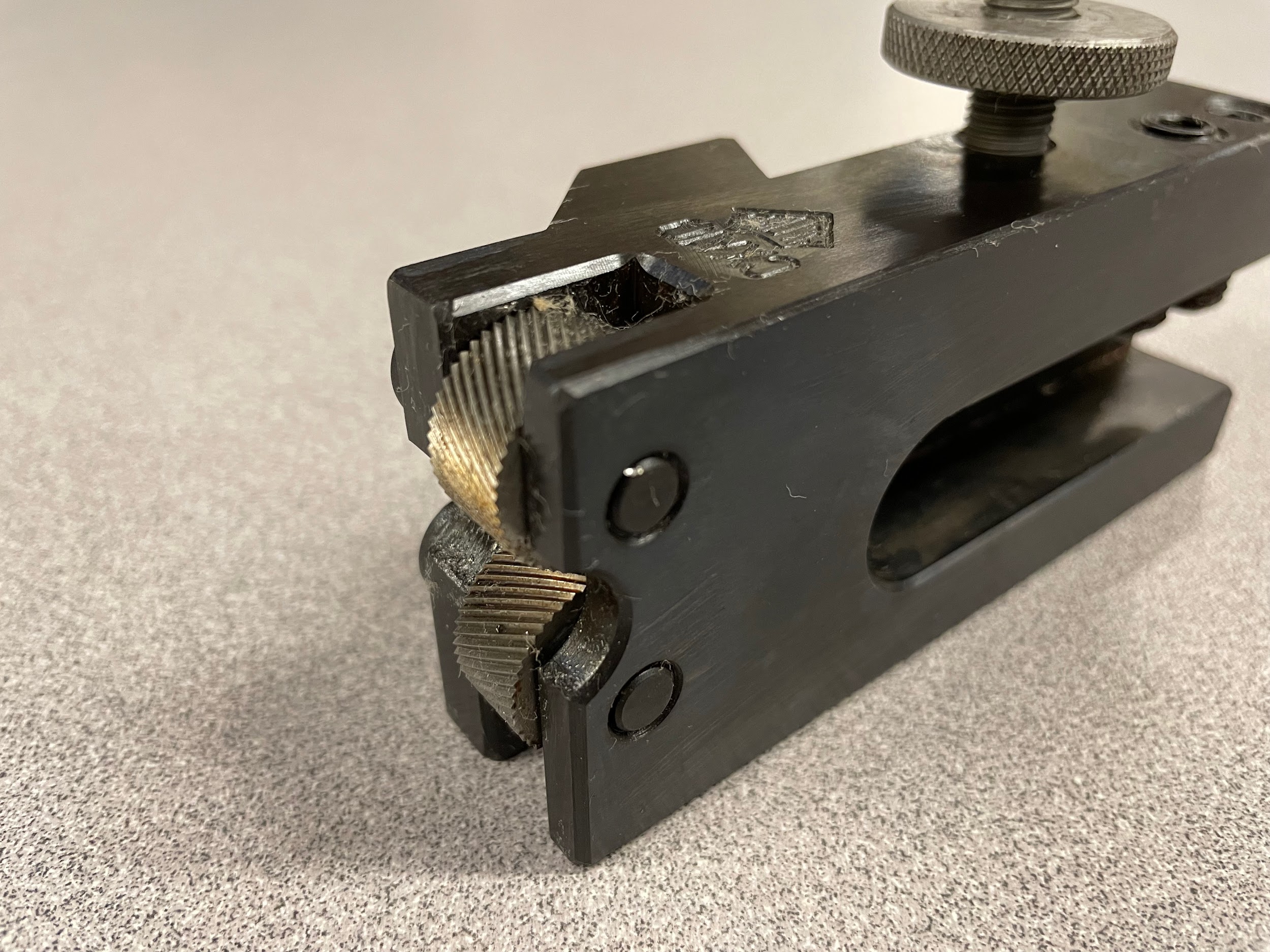
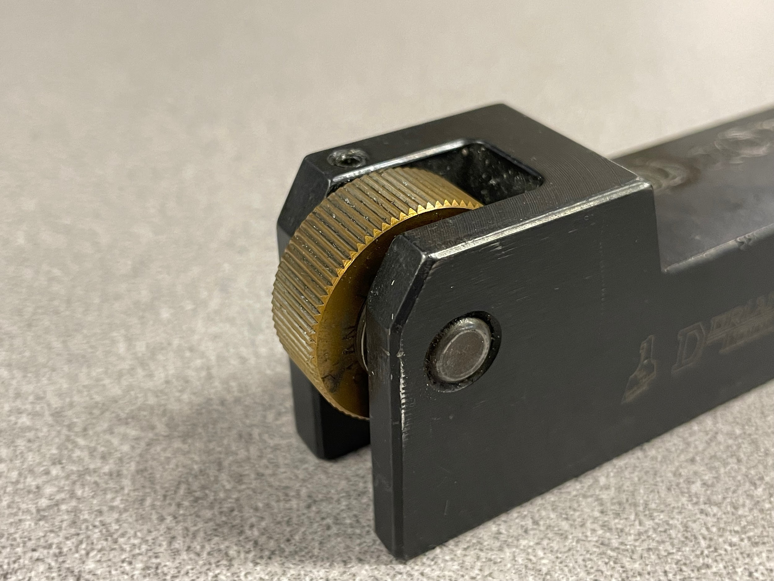
Knurling tools are special tools used to displace the metal on a part and create a pattern for aesthetic reasons and/or gripping purposes. Knurls are found in many shapes and sizes. The most common knurls are the diamond pattern and the straight knurl. Both of these knurl types come in different sizes depending on the application of the part. A classic knurling tool is known as a bump knurler because of the bumping action used to engage the tool with the work. More modern variations of the knurling tool include the scissor, clamp, and adjustable knurling tools. These variations are popular because they put less force on the headstock bearings and cross slide screw. They are also easier to use, and they provide good results.
Attributions
- Figure 10.64: High speed steel by Micky R. Jennings, courtesy of Wenatchee Valley College, for WA Open ProfTech, © SBCTC, CC BY 4.0
- Figure 10.65: Brazed carbide tooling by Micky R. Jennings, courtesy of Wenatchee Valley College, for WA Open ProfTech, © SBCTC, CC BY 4.0
- Figure 10.66: Various holders and inserts by Micky R. Jennings, courtesy of Wenatchee Valley College, for WA Open ProfTech, © SBCTC, CC BY 4.0
- Figure 10.67: 80 degree trigon tool by Micky R. Jennings, courtesy of Wenatchee Valley College, for WA Open ProfTech, © SBCTC, CC BY 4.0
- Figure 10.68: 55 degree diamond tool by Micky R. Jennings, courtesy of Wenatchee Valley College, for WA Open ProfTech, © SBCTC, CC BY 4.0
- Figure 10.69: Grooving tool by Micky R. Jennings, courtesy of Wenatchee Valley College, for WA Open ProfTech, © SBCTC, CC BY 4.0
- Figure 10.70: Top notch style grooving tool by Micky R. Jennings, courtesy of Wenatchee Valley College, for WA Open ProfTech, © SBCTC, CC BY 4.0
- Figure 10.71: Top notch style grooving tool by Micky R. Jennings, courtesy of Wenatchee Valley College, for WA Open ProfTech, © SBCTC, CC BY 4.0
- Figure 10.72: Boring bar by Micky R. Jennings, courtesy of Wenatchee Valley College, for WA Open ProfTech, © SBCTC, CC BY 4.0
- Figure 10.73: Threading bar by Micky R. Jennings, courtesy of Wenatchee Valley College, for WA Open ProfTech, © SBCTC, CC BY 4.0
- Figure 10.74: Part-off blade by Micky R. Jennings, courtesy of Wenatchee Valley College, for WA Open ProfTech, © SBCTC, CC BY 4.0
- Figure 10.75: Form tools by Micky R. Jennings, courtesy of Wenatchee Valley College, for WA Open ProfTech, © SBCTC, CC BY 4.0
- Figure 10.76: Scissor knurling tool by Micky R. Jennings, courtesy of Wenatchee Valley College, for WA Open ProfTech, © SBCTC, CC BY 4.0
- Figure 10.77: Scissor knurling tool 2 by Micky R. Jennings, courtesy of Wenatchee Valley College, for WA Open ProfTech, © SBCTC, CC BY 4.0
- Figure 10.78: Bump knurling tool by Micky R. Jennings, courtesy of Wenatchee Valley College, for WA Open ProfTech, © SBCTC, CC BY 4.0
- Figure 10.79: Bump knurling tool by Micky R. Jennings, courtesy of Wenatchee Valley College, for WA Open ProfTech, © SBCTC, CC BY 4.0
Please look for related terms in the Glossary
Cutting tools that are designed for grooving operations.
Cutting tools that are designed for threading operations.
Cutting tools that are designed for boring operations.
Cutting tools that are designed for internal grooving operations.
Cutting tools that are designed for internal threading operations.
Cutting tools that are designed for parting operations.
A tool that is used to cut a specific shape on a part, often in a single linear cut. The tool is made to be the inverse of the shape required on the part.
Cutting tools that are designed for knurling operations. See Knurling.
