10.8 Tool Setup
Micky R. Jennings
Setting up tooling on a lathe requires some checks and adjustments to make sure the cutting process will be successful. When using modern inserted tooling and a quick change tool post on a manual lathe, it is ideal to set the tooling up like it was designed to be used. Setting the tooling up in this manner will give adequate clearance where it is required. The first check will be to the insert itself. The next step will be the correct orientation of the tool. Then check the height or the tool. Lastly, tools are set up in the tailstock. Each of these components is important, and when any one of them is neglected, the operator may have difficulty with the cutting process.
Insert Replacement
It is important to check cutting tool edges from time to time to ensure they are sharp, free from damage, and in good working order. Often, an experienced machinist can tell something is wrong with a cutting edge by noticing a difference in the part, the sound the machine is making, or the chips that are coming off the tool. For tooling made of HSS, this would mean taking the entire tool out of the tool post, resharpening it, and redoing the setup of the tool. With the use of modern carbide inserts, much of that headache is gone. Carbide inserts have multiple cutting edges per piece and often repeat their location with an accuracy of less than .001. This allows the operator to rotate an insert in much less time than it would take to fix a dull HSS tool.
Step by step process for replacing indexable inserts:
- Leave the tool on the tool post and in the quick-change tool holder.
- Clean all the chips, oil, and residue from the insert, clamp, and screw heads.
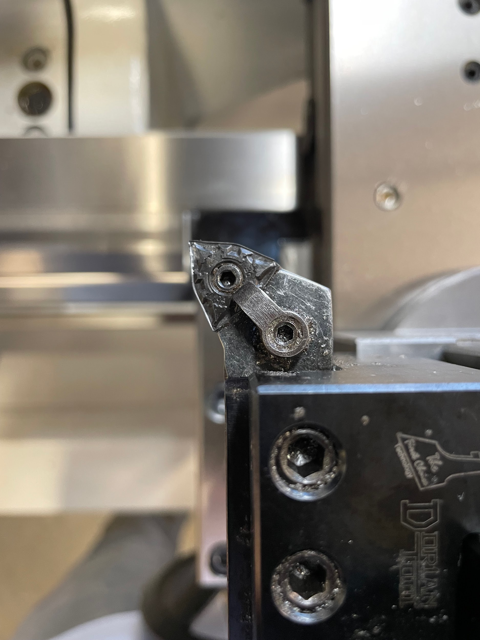
- Inspect the insert.
- Use the appropriate tool to loosen the hold down clamp and move it to the side, If this is really dirty, the hold down clamp may need to be completely removed and cleaned. Some tools may not have this clamp.
- Use the appropriate tool to loosen and remove the alignment screw holding the insert and insert backing plate in place.
- Clean the insert seat meticulously. A little cleaning solution on a cotton swab helps to get into the small crevices.
- Clean the insert and backing plate with a rag. Some insert holders may not have a backing plate.
- Clean the screws by holding them tightly with a rag and rotating them with the hex key.
- Inspect the insert, looking for an unused cutting edge. If one can’t be found, the insert needs to be replaced.
- Start reassembling the tool by setting the backing plate on the bottom of the pocket.
- Start the thread of the alignment screw. Do not tighten.
- Place the insert over the alignment screw and press it down onto the backing plate.
- While holding downward pressure on the insert, gently tighten the alignment screw. Do not overtighten! This screw is easily stripped and is only used to position the insert in the pocket and not to hold it.
- Replace the clamp and screw in the opposite direction. This screw can be adjusted a little tighter but be mindful of the limitations of the tooling used to turn these little screws.
Step 3: Inspect the insert.
Step 4-5: Use the appropriate tool to loosen the hold down clamp and move it to the side. If this is really dirty, the hold down clamp may need to be completely removed and cleaned. Some tools may not have this clamp. Use the appropriate tool to loosen and remove the alignment screw holding the insert and insert backing plate in place.

Step 6-8: Clean the insert seat meticulously. A little cleaning solution on a cotton swab helps to get into the small crevices. Clean the insert and backing plate with a rag. Some insert holders may not have a backing plate. Clean the screws by holding them tightly with a rag and rotating them with the hex key.
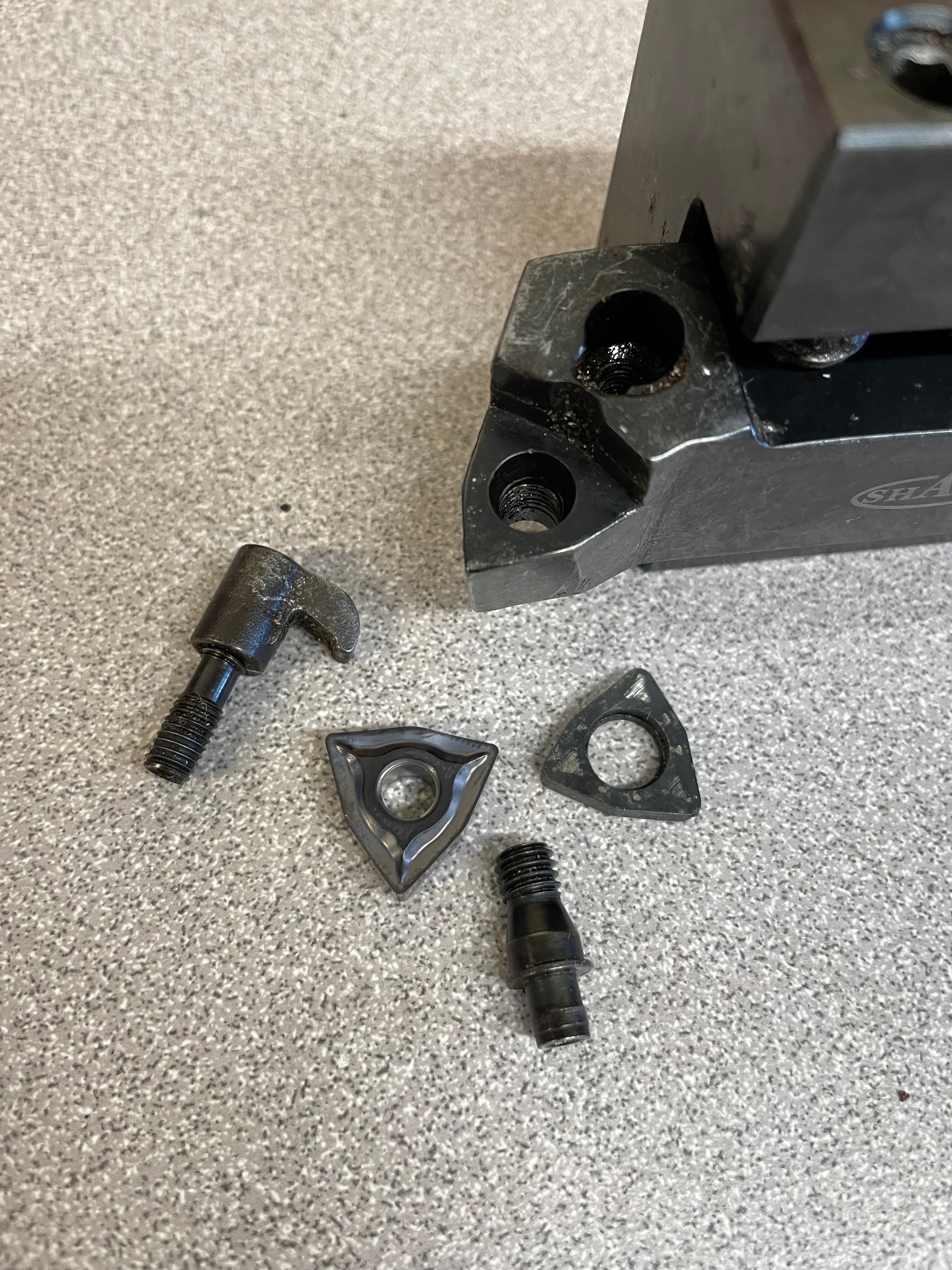
Step 10-14: Start reassembling the tool by setting the backing plate on the bottom of the pocket. Start the thread of the alignment screw. Do not tighten. Place the insert over the alignment screw and press it down onto the backing plate. While holding downward pressure on the insert, gently tighten the alignment screw. Do not overtighten! This screw is easily stripped and is only used to position the insert in the pocket and not to hold it. Replace the clamp and screw in the opposite direction. This screw can be adjusted a little tighter but be mindful of the limitations of the tooling used to turn these little screws.

Aligning the Tool Post
Aligning the tool post is an important step in using inserted tooling on a quick-change tool post. Alignment of the tool post allows all the tooling put in the quick-change tool holders to be square to the work. This is an efficient way to work because it allows the proper clearance angles for tools to face, turn, bore, groove, thread, part, etc. without adjusting the tool post. There are some instances when a machinist may want to adjust the tool post to a different angle, but the majority of the operations performed with modern tools are designed for the tools to either be perpendicular or parallel to the work. Aligning the tool post enables the machinist to utilize the design of modern tooling.
Step by step process for aligning the tool post:
- Remove the tool holder from the quick-change tool post.
- Loosen the nut on the top of the tool post.
- Locate a surface on the lathe that is parallel or perpendicular to the center axis of spindle rotation. This can be the side of the chuck, the face of the chuck, clean face of the work, or the tailstock quill.
- Move the carriage and the cross slide so the tool post is up against the parallel or perpendicular surface.
- Tighten by hand and move the tool post away from the surface. Moving away before tightening with a wrench ensures the tool post or surface will not be damaged if the tool post rotates.
- Tighten the tool post nut with a wrench. On most machines, this nut can handle and will require a decent amount of torque. Review the owner’s manual for the tool post for the exact torque specs.
- Bring the tightened tool post back against the surface and inspect the alignment. Repeat the process if the tool post is not aligned.
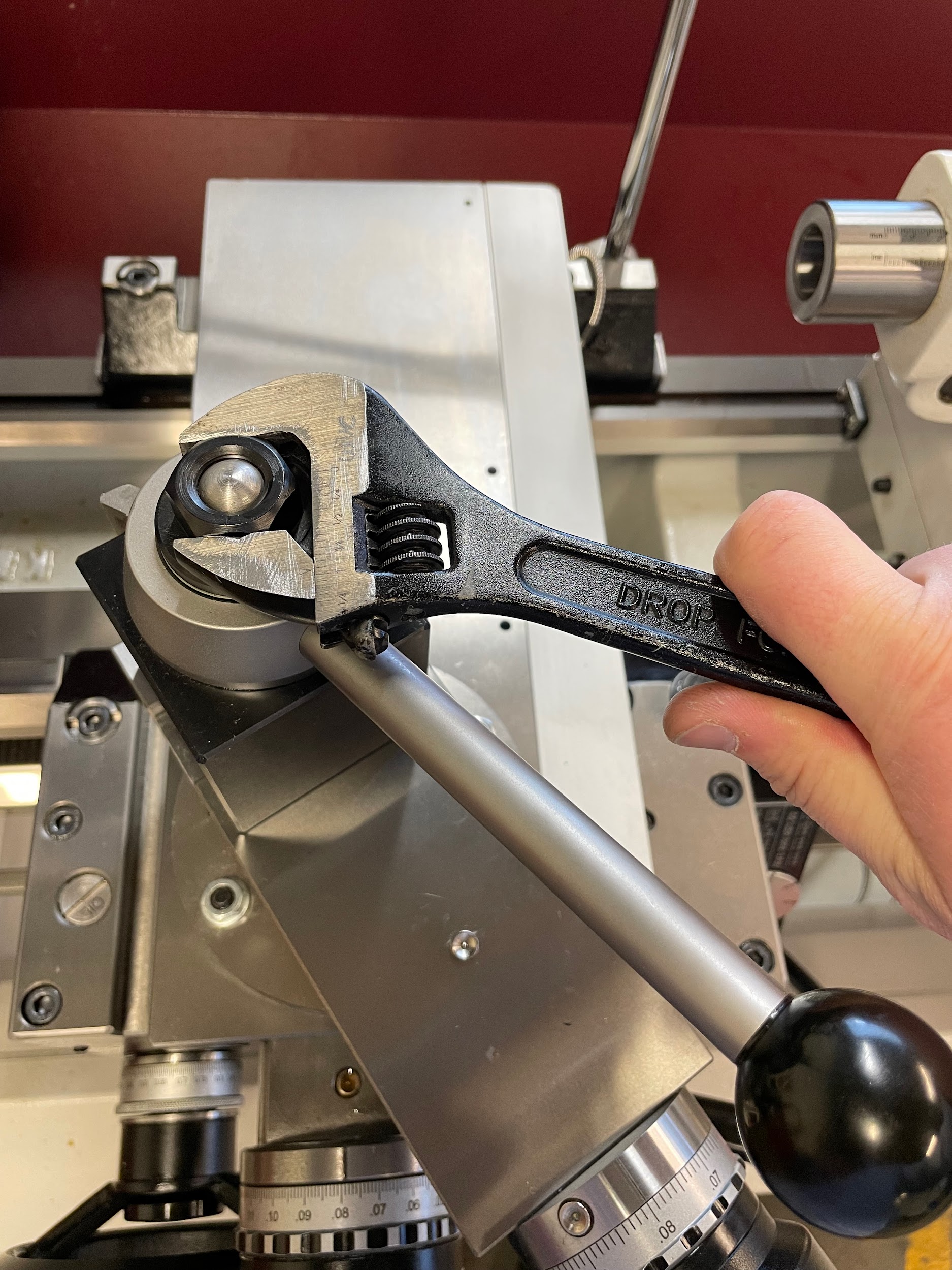
Step 2: Loosen the nut on the top of the tool post.
Step 4: Move the carriage and the cross slide so the tool post is up against the parallel or perpendicular surface.
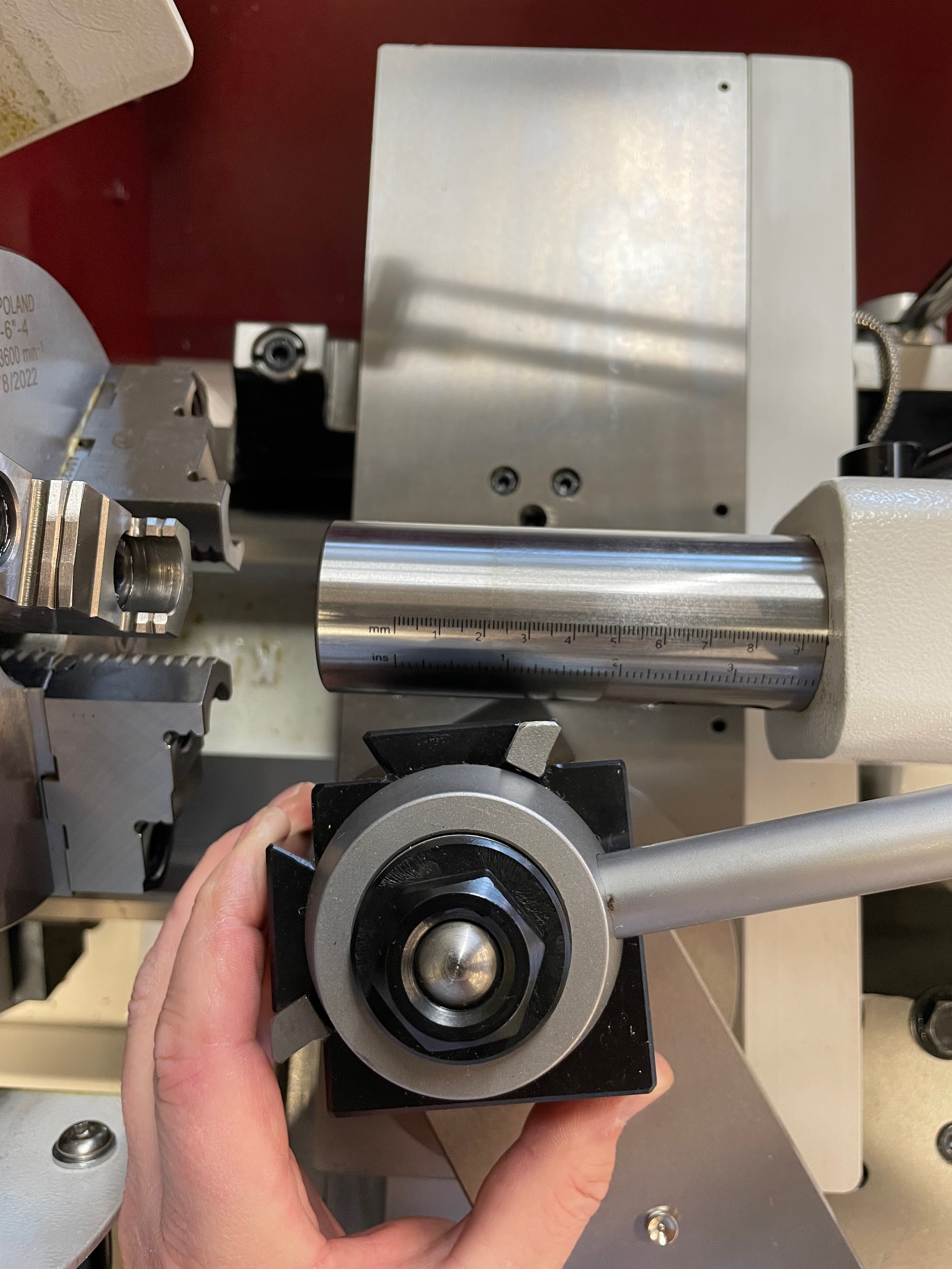
Step 4: Move the carriage and the cross slide so the tool post is up against the parallel or perpendicular surface.

Step 4: Move the carriage and the cross slide so the tool post is up against the parallel or perpendicular surface.
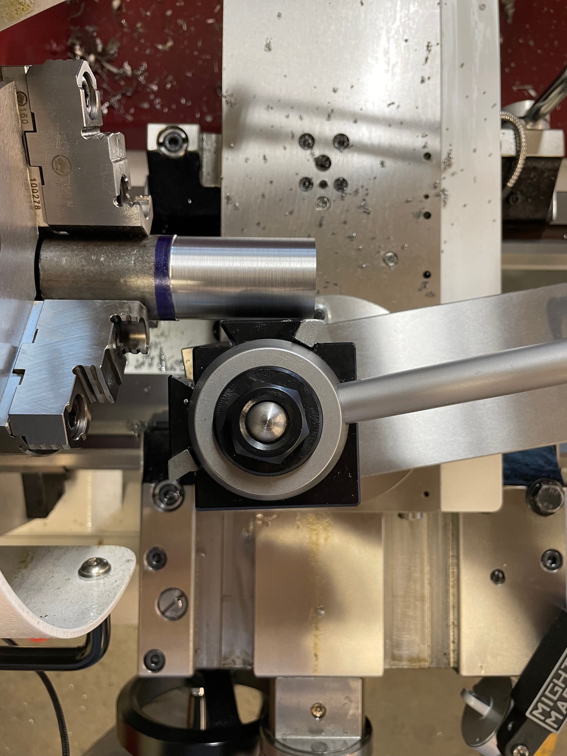
Step 4: Move the carriage and the cross slide so the tool post is up against the parallel or perpendicular surface.

Tool Height Centering
Setting the height of the cutting tools is an important process, regardless of the tool material or the tool post. Proper cutting can only happen when the tip of the tool is at the same height as the center of the spindle rotation. This can be done by a few different methods. One method is using the center in the tailstock to gauge the tool height; another uses a steel rule to see where the tool touches on the outside of a cylindrical workpiece.
Step by step process for adjusting the tool height with the tailstock center:
- Load a center in the tailstock.
- Load and tighten the tool holder onto the quick-change tool post so that the tip of the tool or end of the bar is facing the tailstock.
- Bring the tailstock up to the tool and lock it in place.
- Gently move the carriage and cross slide so the tool is close to the center tip.
- Inspect the height of the tool tip or end of the bar to the tip of the center. This requires the operator to have their eyes level and at the same height as the tool and tip. This can’t properly be done from a full standing position.
- If the height of the tool is different than the tip of the center, loosen the quick-change feature of the tool post, adjust the tool height, tighten, and recheck.
- When the height of the tool is correct, tighten the lock nut to secure the height.
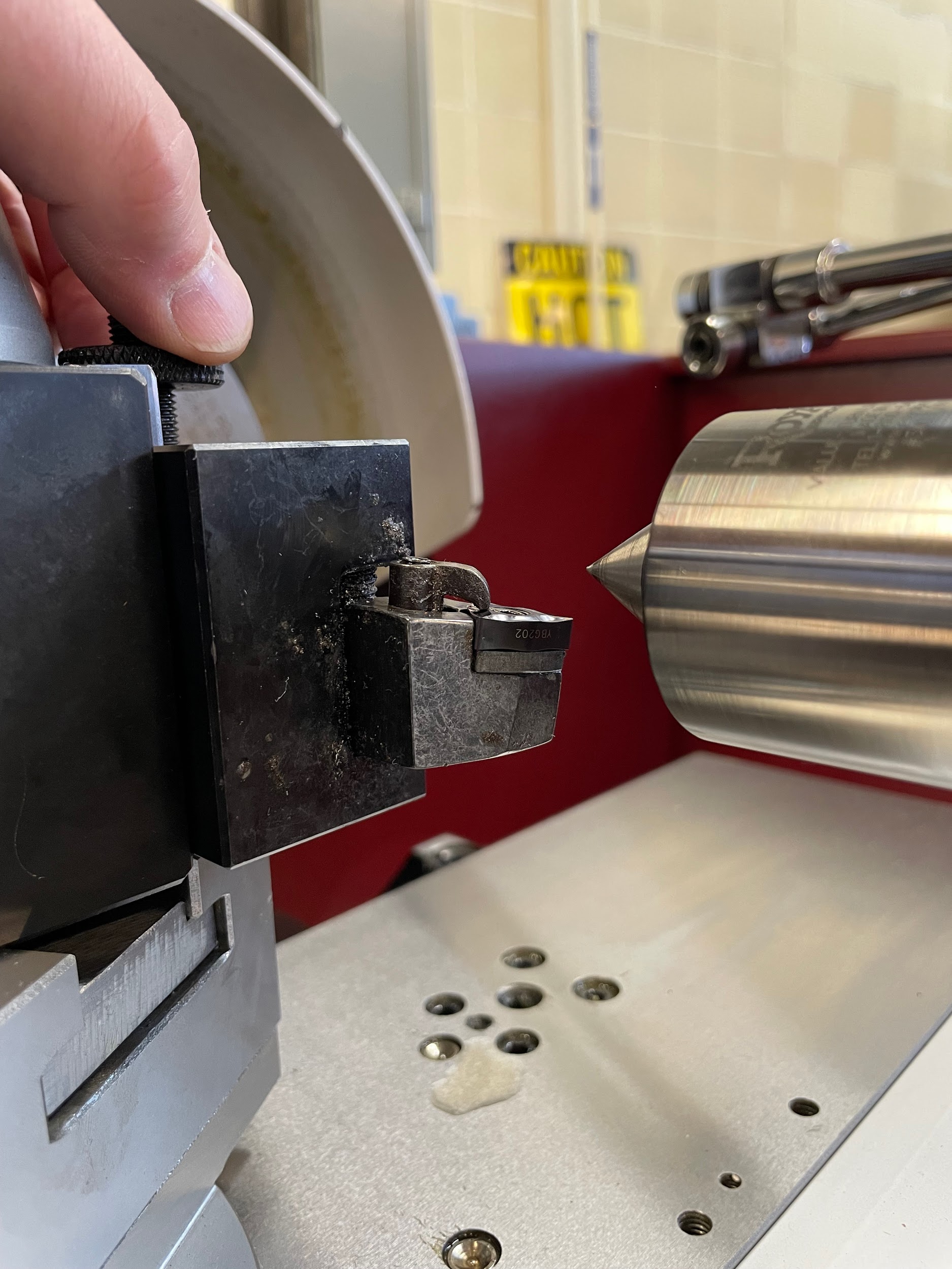
Step 4: Gently move the carriage and cross slide so the tool is close to the center tip.
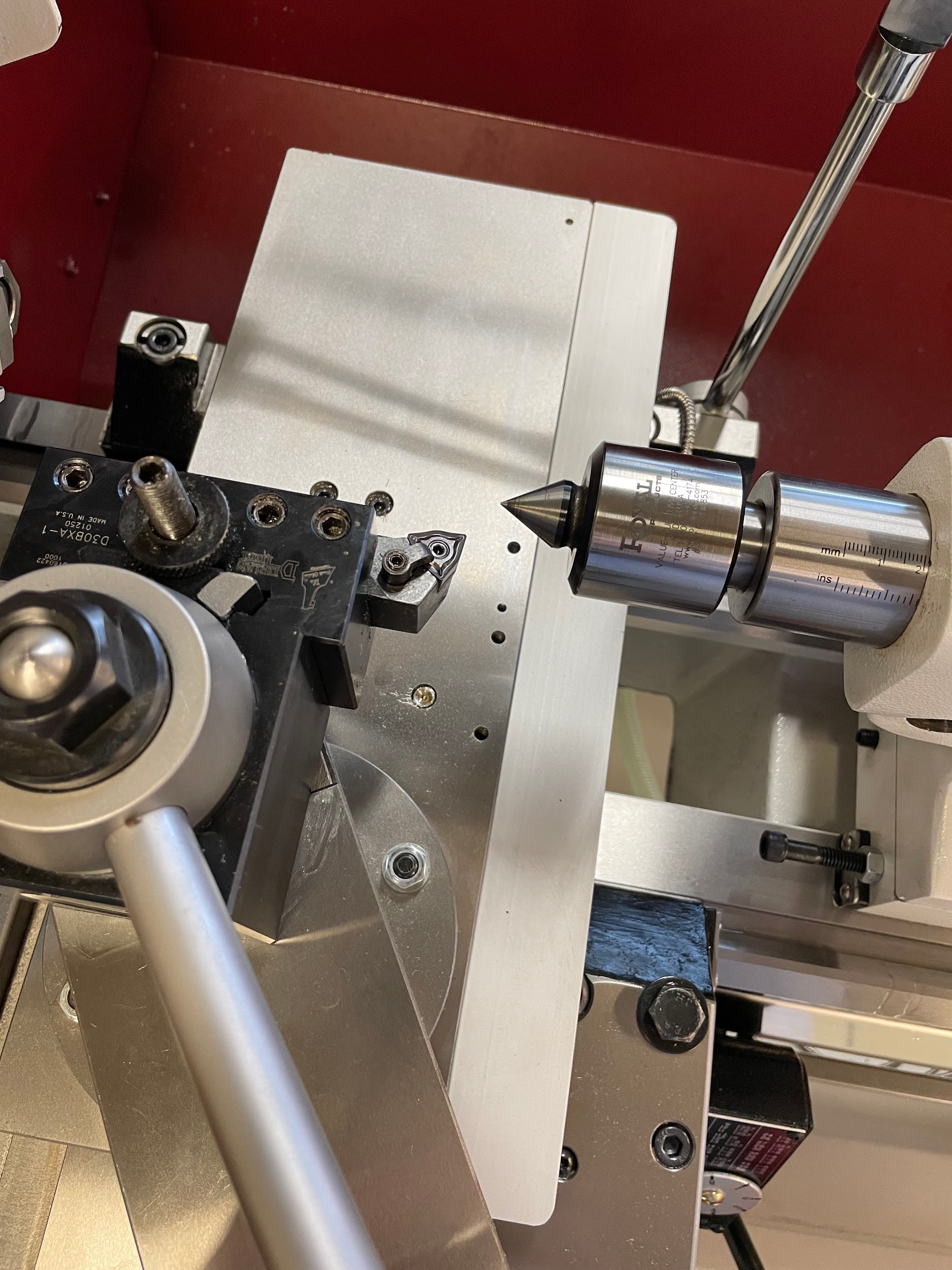
Step 5: Inspect the height of the tool tip or end of the bar to the tip of the center. This requires the operator to have their eyes level and at the same height as the tool and tip. This can’t properly be done from a full standing position.
Step 6: If the height of the tool is different than the tip of the center, loosen the quick-change feature of the tool post, adjust the tool height, tighten, and recheck.

Step by step process for adjusting the tool height with a scale on the work:
- Load job material into the lathe spindle.
- Load and tighten the tool holder onto the quick-change tool post.
- Move the carriage and cross slide so the tool is within ⅛” of the outside diameter of the stock.
- Place a 6″ flexible steel rule in between the tool tip and the work.
- Gently bring the tip of the tool up to the rule and lightly hold it against the side of the work with the pressure from the cross slide. Caution must be taken at this step, tool tips and carbide inserts can be chipped or broken with too much force.
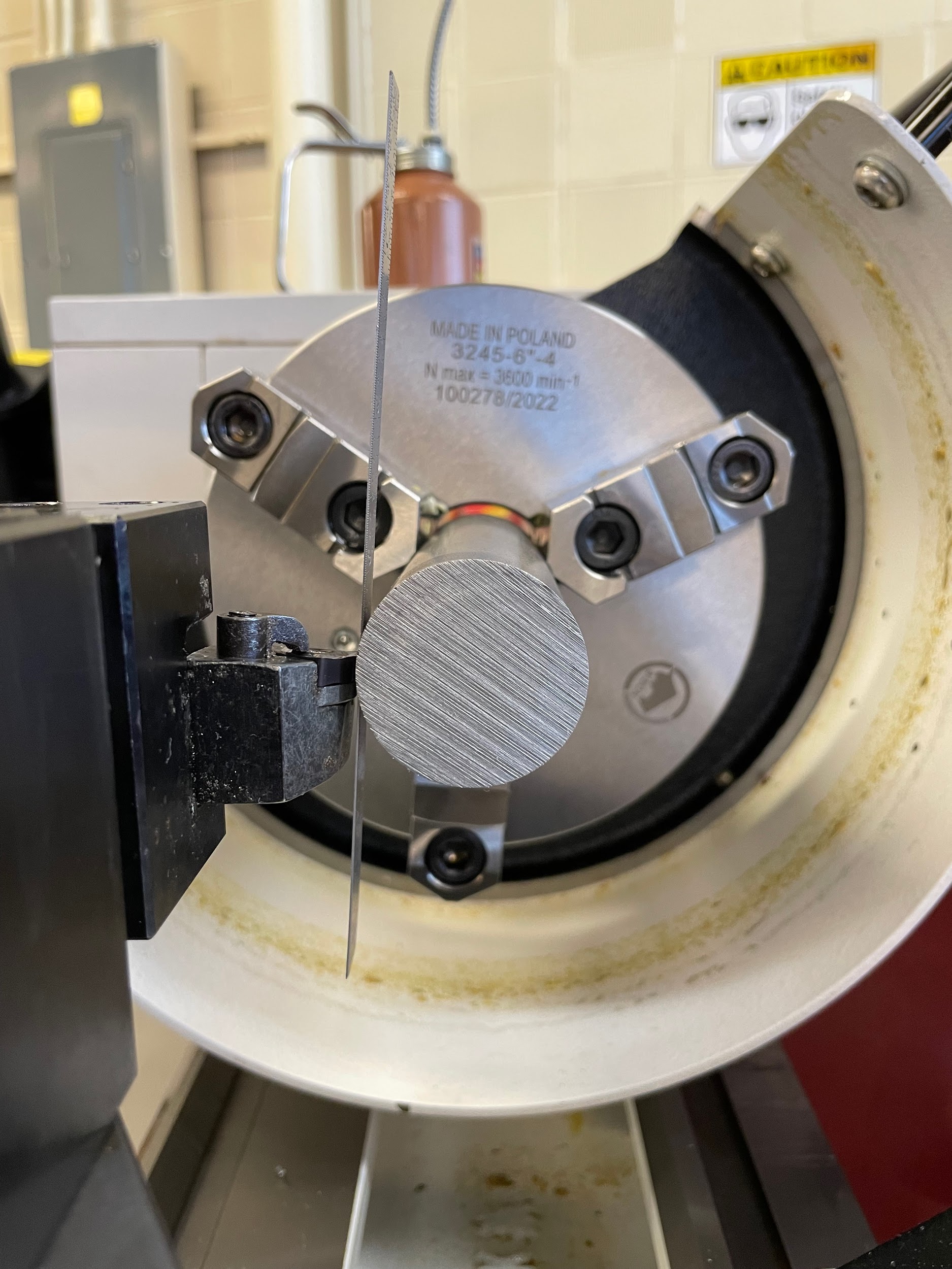
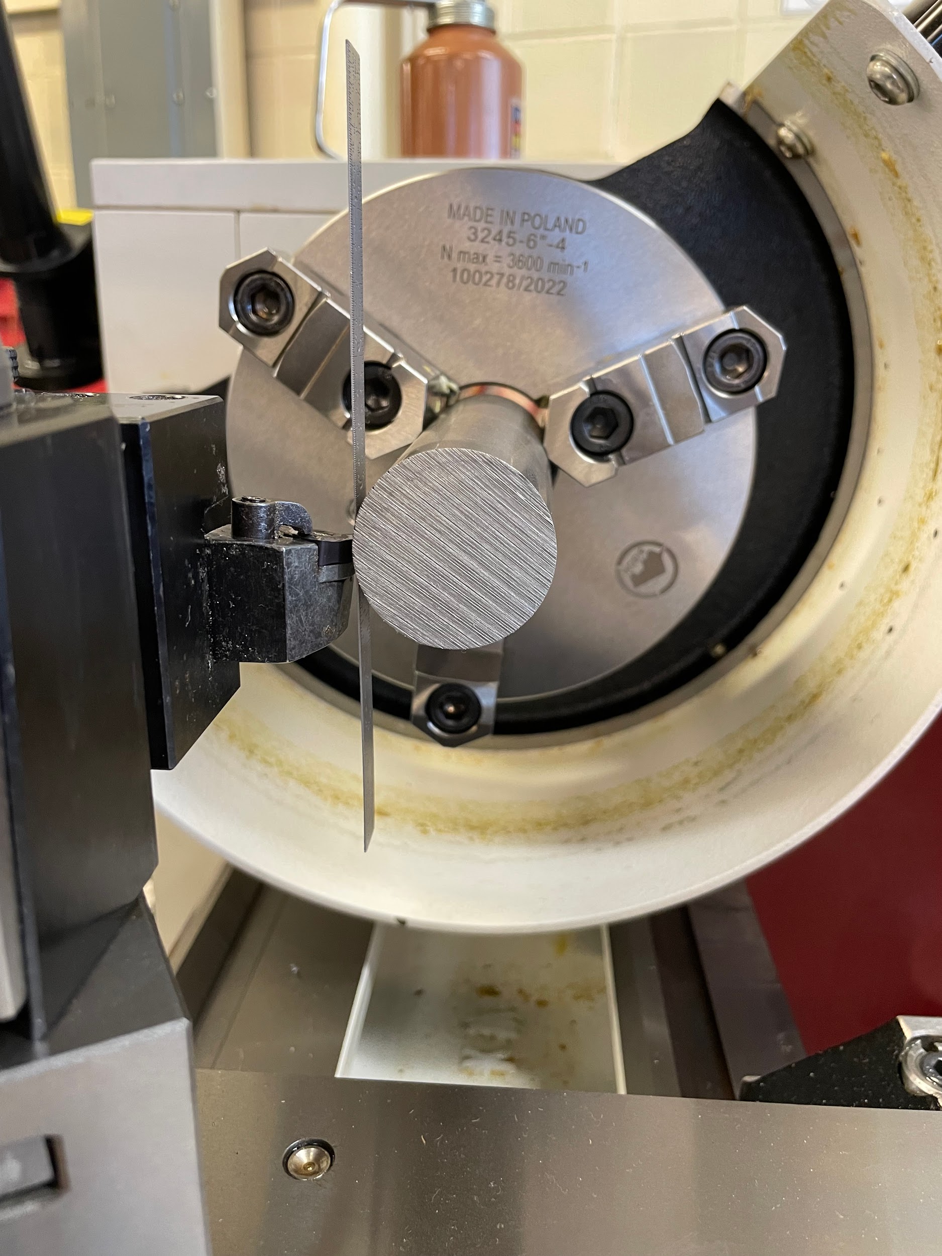
- The height of the tool can be checked by looking at how vertical the rule is. A rule at a clockwise angle indicates a tool that is too high. A rule that is at a counterclockwise angle indicates a tool that is too low. A rule that is vertical indicates a tool that is in the center. This requires the operator to walk to the end of the lathe and look straight at the chuck.
- If the rule is at an angle, back off the cross slide, loosen the quick-change feature of the tool post, adjust the tool height, tighten, and recheck.
- When the height of the tool is correct, tighten the lock nut to secure the height.
Step 6: The height of the tool can be checked by looking at how vertical the rule is. A rule at a clockwise angle indicates a tool that is too high. A rule that is at a counterclockwise angle indicates a tool that is too low. A rule that is vertical indicates a tool that is in the center. This requires the operator to walk to the end of the lathe and look straight at the chuck.
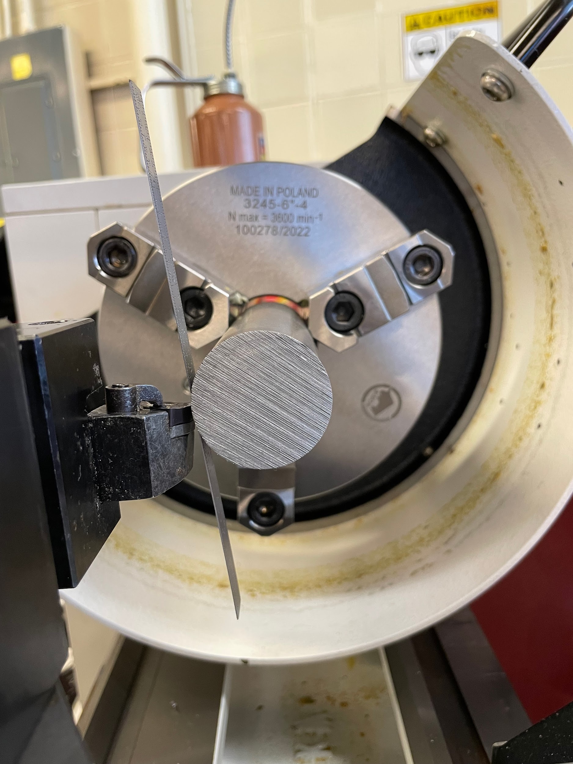
Step 6: The height of the tool can be checked by looking at how vertical the rule is. A rule at a clockwise angle indicates a tool that is too high. A rule that is at a counterclockwise angle indicates a tool that is too low. A rule that is vertical indicates a tool that is in the center. This requires the operator to walk to the end of the lathe and look straight at the chuck.
Step 6: The height of the tool can be checked by looking at how vertical the rule is. A rule at a clockwise angle indicates a tool that is too high. A rule that is at a counterclockwise angle indicates a tool that is too low. A rule that is vertical indicates a tool that is in the center. This requires the operator to walk to the end of the lathe and look straight at the chuck.
Tailstock Tool Removal and Installation
The tailstock is an important component for holding hole making tools on the lathe. It will not only hold the versatile drill chuck that is capable of quickly switching between most of the common hole tooling, but it will also hold large taper shank tooling that will allow the operator to drill large holes using the full power of the lathe’s motor. Lathes are often more powerful than sensitive drill presses and can take impressive cuts and remove large amounts of material in a hurry. Drilling is one of the most efficient ways to remove material. Lathes can often use the largest drills in the shop with the correct tool holding. The tailstock offers the perfect solution in the Morse taper.
Step by step process for removing and installing tailstock taper tooling:
- To remove a taper from the tailstock, reverse the handwheel until it stops. Place the left hand under the tool and forcefully tap the handle of the handwheel with the right hand until the tool taper seat is broken loose.
- Clean and inspect the quill taper as well as the taper of the new tool to be installed.
- Gently slide the taper tool into the taper of the quill, lining up the tang if the tool has one, until reaching the bottom.
- Keeping the same orientation of the tool, pull the tool back out a couple inches.
- In one swift and forceful movement, slap the tool into the quill to seat the taper.
Step 1: To remove a taper from the tailstock, reverse the handwheel until it stops. Place the left hand under the tool and forcefully tap the handle of the handwheel with the right hand until the tool taper seat is broken loose.

Step 2: Clean and inspect the quill taper as well as the taper of the new tool to be installed.
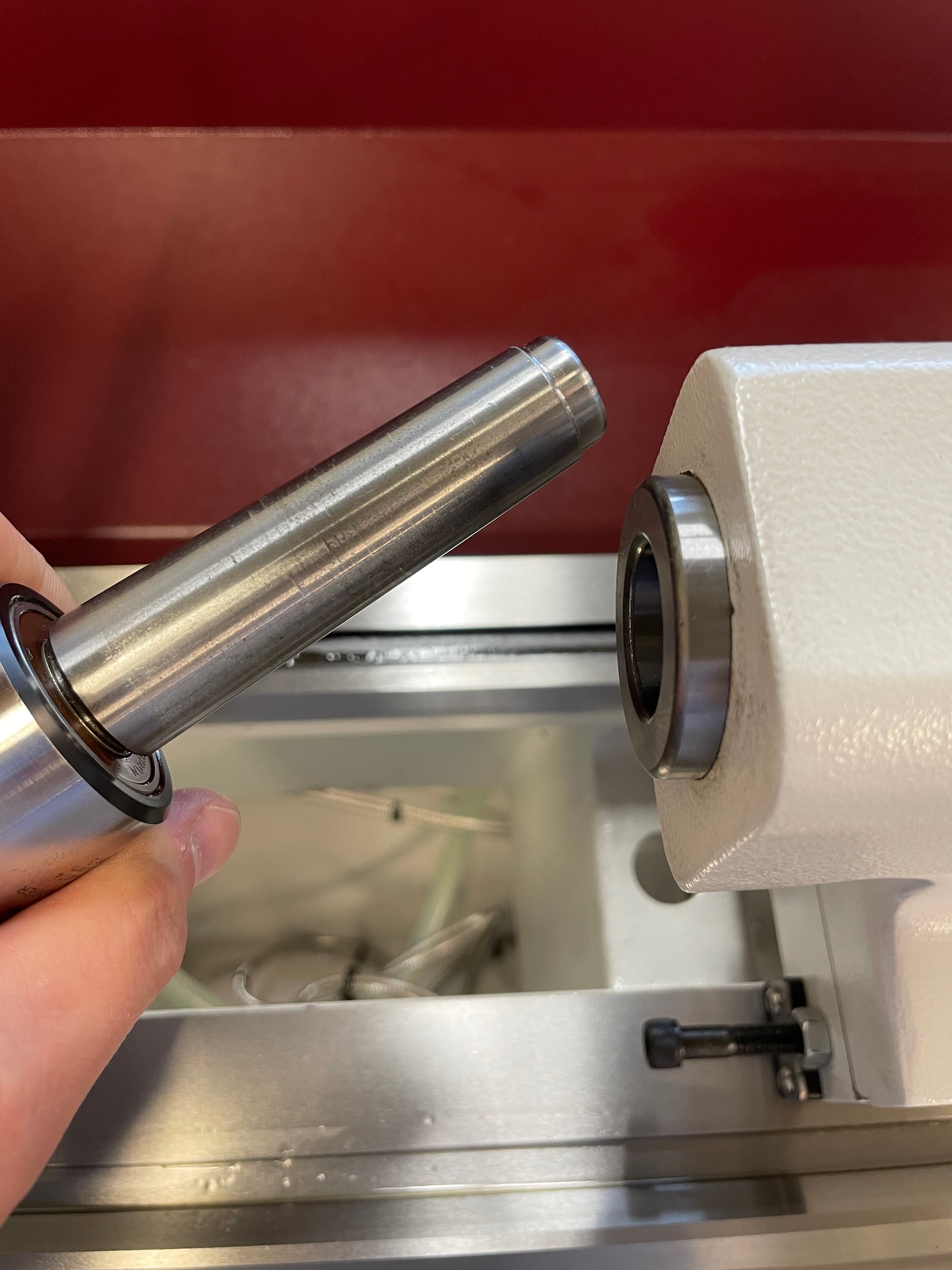
Step 3-5: Gently slide the taper tool into the taper of the quill, lining up the tang if the tool has one, until reaching the bottom. Keeping the same orientation of the tool, pull the tool back out a couple inches. In one swift and forceful movement, slap the tool into the quill to seat the taper.

Step 3-5: Gently slide the taper tool into the taper of the quill, lining up the tang if the tool has one, until reaching the bottom. Keeping the same orientation of the tool, pull the tool back out a couple inches. In one swift and forceful movement, slap the tool into the quill to seat the taper.

Attributions
- Figure 10.80: Inspecting insert by Micky R. Jennings, courtesy of Wenatchee Valley College, for WA Open ProfTech, © SBCTC, CC BY 4.0
- Video 10.24: Micky R. Jennings, courtesy of Wenatchee Valley College, for WA Open ProfTech, © SBCTC, CC BY 4.0
- Figure 10.81: Pieces of carbide tool holder by Micky R. Jennings, courtesy of Wenatchee Valley College, for WA Open ProfTech, © SBCTC, CC BY 4.0
- Video 10.25: Micky R. Jennings, courtesy of Wenatchee Valley College, for WA Open ProfTech, © SBCTC, CC BY 4.0
- Figure 10.82: Loosening tool post by Micky R. Jennings, courtesy of Wenatchee Valley College, for WA Open ProfTech, © SBCTC, CC BY 4.0
- Figure 10.83: Aligning a tool post by Micky R. Jennings, courtesy of Wenatchee Valley College, for WA Open ProfTech, © SBCTC, CC BY 4.0
- Video 10.26: Micky R. Jennings, courtesy of Wenatchee Valley College, for WA Open ProfTech, © SBCTC, CC BY 4.0
- Figure 10.84: Aligning a tool post 3 by Micky R. Jennings, courtesy of Wenatchee Valley College, for WA Open ProfTech, © SBCTC, CC BY 4.0
- Video 10.27: Micky R. Jennings, courtesy of Wenatchee Valley College, for WA Open ProfTech, © SBCTC, CC BY 4.0
- Figure 10.85: Checking tool height by Micky R. Jennings, courtesy of Wenatchee Valley College, for WA Open ProfTech, © SBCTC, CC BY 4.0
- Figure 10.86: Checking tool height by Micky R. Jennings, courtesy of Wenatchee Valley College, for WA Open ProfTech, © SBCTC, CC BY 4.0
- Video 10.28: Micky R. Jennings, courtesy of Wenatchee Valley College, for WA Open ProfTech, © SBCTC, CC BY 4.0
- Figure 10.87: Checking tool height 2 by Micky R. Jennings, courtesy of Wenatchee Valley College, for WA Open ProfTech, © SBCTC, CC BY 4.0
- Figure 10.88: Checking tool height 3 by Micky R. Jennings, courtesy of Wenatchee Valley College, for WA Open ProfTech, © SBCTC, CC BY 4.0
- Figure 10.89: Checking tool height 4 by Micky R. Jennings, courtesy of Wenatchee Valley College, for WA Open ProfTech, © SBCTC, CC BY 4.0
- Video 10.29: Micky R. Jennings, courtesy of Wenatchee Valley College, for WA Open ProfTech, © SBCTC, CC BY 4.0
- Figure 10.90: Morse taper 2 by Micky R. Jennings, courtesy of Wenatchee Valley College, for WA Open ProfTech, © SBCTC, CC BY 4.0
- Video 10.30: Micky R. Jennings, courtesy of Wenatchee Valley College, for WA Open ProfTech, © SBCTC, CC BY 4.0
- Video 10.31: Micky R. Jennings, courtesy of Wenatchee Valley College, for WA Open ProfTech, © SBCTC, CC BY 4.0
