10.9 Spindle Speed, Feed Rate, Depth Of Cut And Finish Allowances
Micky R. Jennings
Spindle Speed
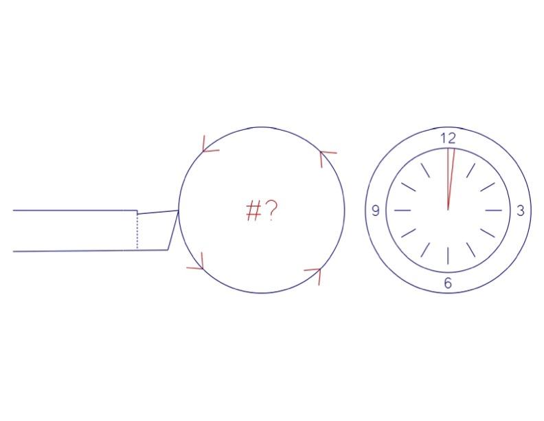
Lathe spindle speeds are calculated very similarly to other machining processes. The machinist will use the same formula in its simplified form to calculate RPM:
RPM = SFPM × 4 / Diameter
In the case of the lathe, the diameter refers to the point at which the tool touches the workpiece. For example, if there was a HSS turning tool cutting a 2″ piece of mild steel, the calculation would look as follows.
RPM = SFPM × 4 / Diameter
RPM = 100 × 4 / 2
RPM = 400 / 2
RPM = 200
This calculation is just to get a foot in the door and start creating chips. Many factors could alter this spindle speed, and the operator may need to adjust accordingly.
Carbide tooling is much stronger and more temperature and abrasion resistant than HSS. For these reasons, it can be used at a much higher SFPM than HSS. With the case of carbide inserts, the manufacturer will give a range of SFPM that is most optimal for the tool to operate. Whenever possible, use the numbers provided by the manufacturer as a guide. Sometimes, with some general use carbide, that data isn’t available, and so going with a conservative estimate usually works well to get out of the gate. A good starting number is 4 x the SFPM of HSS.
An example of this calculation cutting 2″ mild steel with a carbide insert would be.
RPM = SFPM × 4 / Diameter
RPM = 400 × 4 / 2
RPM = 1600 / 2
RPM = 800
Author’s Tip
I will usually make a conservative calculation based on general numbers and then adjust as I am running the parts. I mainly look at chip color when working with a rigid setup. A majority of the heat of a cutting operation will be in the chip produced, so the chips are a good indicator of the temperature at the point of contact. HSS has a lower working temperature, so I will increase my spindle speed to where I can achieve a straw to golden yellow color (400 degrees). With a carbide insert that can withstand more heat, I will adjust until I get a purple to blue-colored (550 degree) chip.
Feed Rate
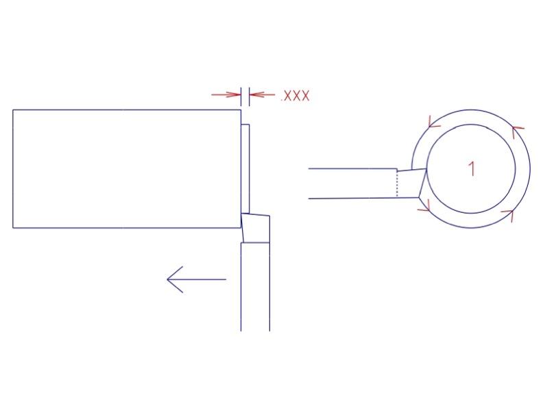
Feed rates used on a lathe are determined by multiple factors. Operation, surface finish, tool nose, and tool type are all aspects to be considered. When using carbide inserted tooling, the manufacturer is a good place to look for this information. They will give the operator feed rates in Inches Per Revolution (IPR) that will give the best tool life. Using that information, coupled with the part surface finish requirements, will give the best results.
Depth of Cut
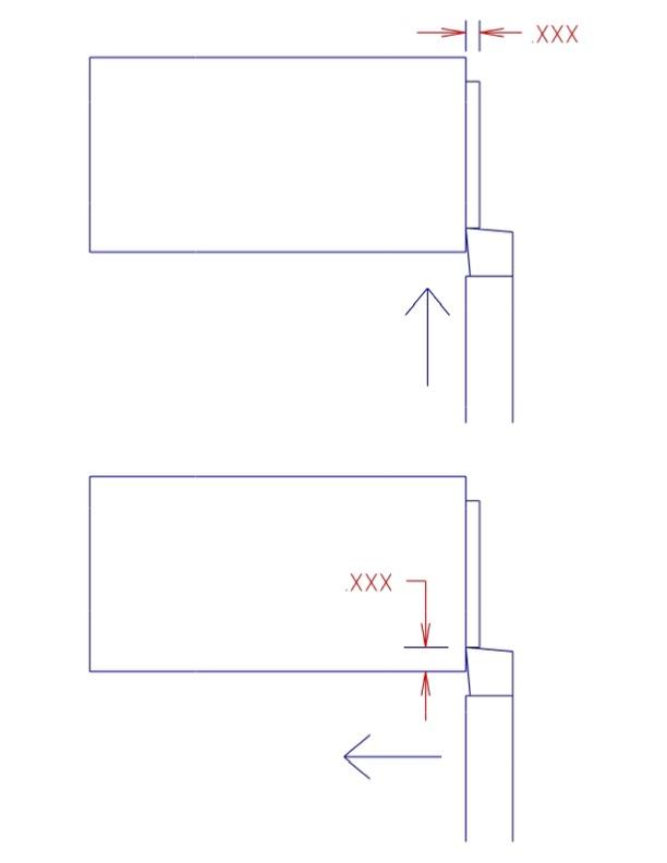
The insert manufacturer is also an excellent place to look for the recommended depth of cut for an insert. Depth of cut is the one cutting condition variable that can be altered with the least effects on tool life. Spindle speed and cutting feed rate will shorten tool life more quickly than depth of cut.
Finishing Allowance
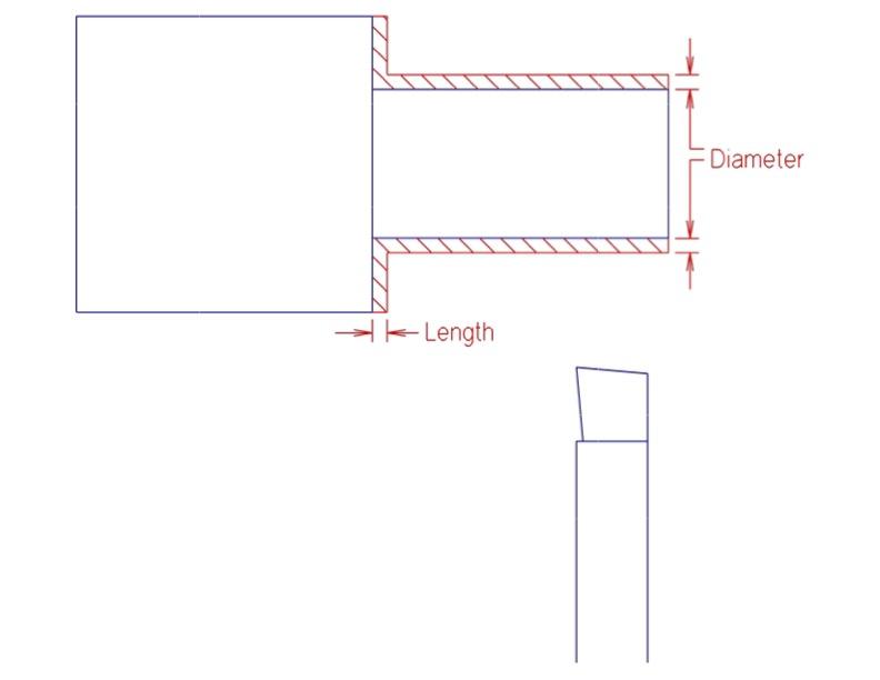
The finishing allowance is the intentional amount of material left on surfaces by the roughing tool. This remaining material is removed by the finishing tool when the part is brought to final size.
The size of the finishing allowance depends on the type of tool used for the cuts. Because of the way carbide inserts remove material it is often not a good plan to attempt small depths of cut. For this reason, a diameter increase of 1/32″, and a length of 1/64″ is recommended. The remaining material can be removed in two finish cuts of equal size, measuring between the two. This practice will give the machinist a more accurate final size because the pressures between the two finish passes will behave more similarly to one another than the heavy roughing cuts.
High speed steel and cement often have shapely ground edges and cut more freely than carbide. Because of this, they are capable of much lighter cuts, sometimes .001 or less. Many carbide inserts will ride up on small depths, burnishing the surface instead of cutting it.
Author’s Tip
Speaking in general terms, our roughing operations are going to be fed faster and deeper than the finishing cuts. For that reason, when roughing a part, I choose somewhere in the .010 IPR range for feed rate, and at a depth of cut the machine can handle. I like to start off small and increase the depth until I can hear the machine working. I keep my depths at an increment that is easy to count by. Don’t use .037 as an incremental depth because you will foul yourself up in the addition at some point. My favorite increment depths are multiples of .010 or .025.
For finishing operations, I am really looking at the accuracy of the feature and the surface finish callout. If the part I am turning has a +- .020 tolerance, I may not spend the time to switch to a finishing tool or slow my feed rate down. Just rough it right to size. However, if I see ± .005 or less, I am going to use a separate tool and set my feed about half as fast at about .005 IPR. It is important for me to note that the tool nose radius also plays an important role in surface finish. The smaller the nose radius is, the slower the feed rate has to be to achieve acceptable surface finishes.
Attributions
- Figure 10.91: Rotation per minute – Lathe by Micky R. Jennings, courtesy of Wenatchee Valley College, for WA Open ProfTech, © SBCTC, CC BY 4.0
- Figure 10.92: Feed rate – lathe by Micky R. Jennings, courtesy of Wenatchee Valley College, for WA Open ProfTech, © SBCTC, CC BY 4.0
- Figure 10.93: Depth of cut – lathe by Micky R. Jennings, courtesy of Wenatchee Valley College, for WA Open ProfTech, © SBCTC, CC BY 4.0
- Figure 10.94: Finishing allowance – lathe by Micky R. Jennings, courtesy of Wenatchee Valley College, for WA Open ProfTech, © SBCTC, CC BY 4.0
The rate at which a spindle is rotating. Often expressed in rotations per minute (RPM).
The rate at which a machine axis is moving. Often expressed in inches per minute (IPM).
The amount a cutting tool is engaged in the material as measured along an axis perpendicular to the cutting axes.
The amount of material that is intentionally left after roughing operations, for finishing passes.
