10.10 Facing
Micky R. Jennings

Facing on a lathe is the process of making a radial cut along the end of the workpiece. It is generally the first cut made and serves as a starting point on which many of the other processes are based. Before making the facing cut, the material is often a rough saw cut that isn’t square and is out of general surface finish tolerance. Facing is generally performed in multiple roughing cuts and at least one finishing cut.
Step by step process for facing:
- Chuck up on material in either a three or four jaw chuck and dial in to suit requirements.
- Load a right-handed turning tool onto the squared tool post.
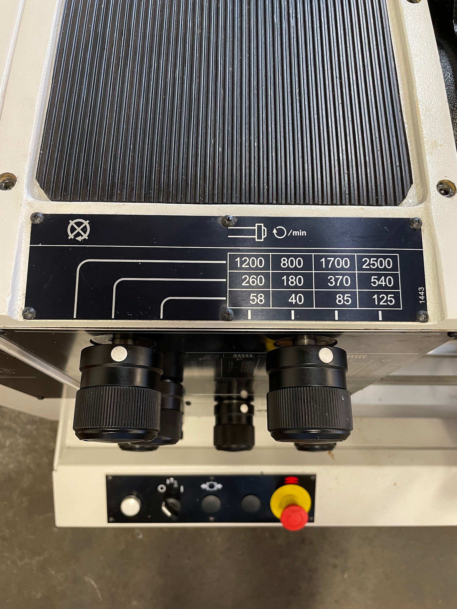
- Calculate and set the proper spindle speed for the combination of cutting tool and material to be used.
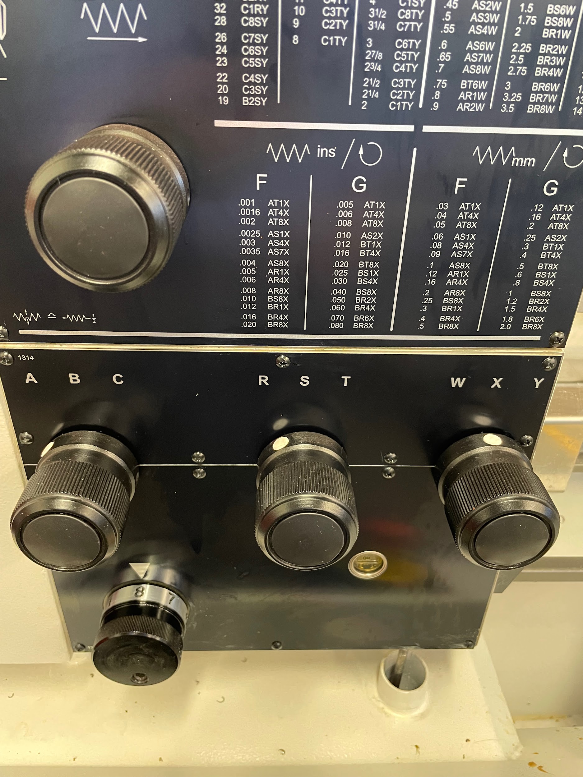
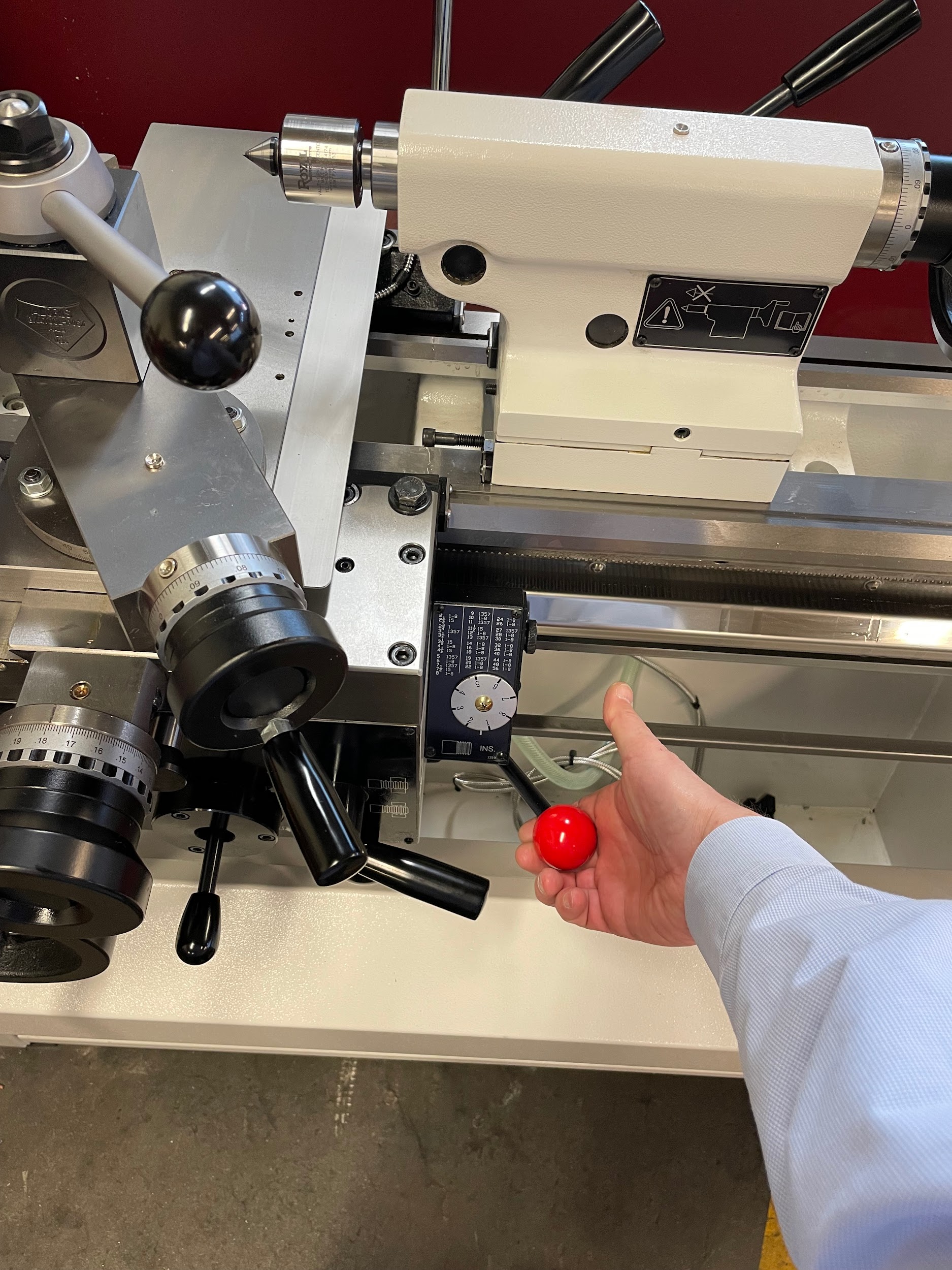
- Set the quick-change gear box for the feed rate desired to travel across the face of the work.
- Turn the spindle on.
- Manipulate the carriage and cross feed hand wheels to bring the cutting tool close to the face of the part and about 1/8″ inside of the outer diameter.
- Gently turn the carriage handwheel until the tip of the cutting tool starts touching the end of the work.
- Back the tool out past the outer diameter using the cross slide handwheel.
- Adjust the graduated collar on the carriage handwheel to zero.
- Turn the carriage hand wheel in .005 or .010. to make an initial cut.
- Lock the carriage movement.
- Engage the cross-slide power feed.
- Allow the cutting tool to travel across the face of the work and disengage the power feed once the tool reaches the center.
- Inspect the face of the work and continue making successive cuts until the face has been cut all the way across.
- Once the last pass is finished, and before moving the carriage, zero the graduated collar again. This is to prepare for turning the OD of the work a specific distance.
- Deburr the edge of the face with a file as the spindle is rotating. Hold the file handle in the left hand and the end of the file in the right hand to keep from reaching over the chuck.
Step 1: Chuck up on material in either a three or four jaw chuck and dial in to suit requirements.
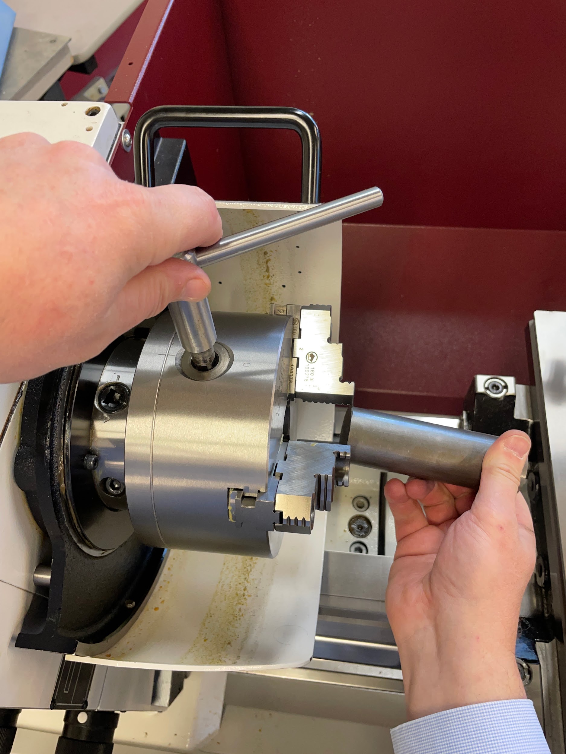
Step 1: Chuck up on material in either a three or four jaw chuck and dial in to suit requirements.

Step 2: Load a right-handed turning tool onto the squared tool post.
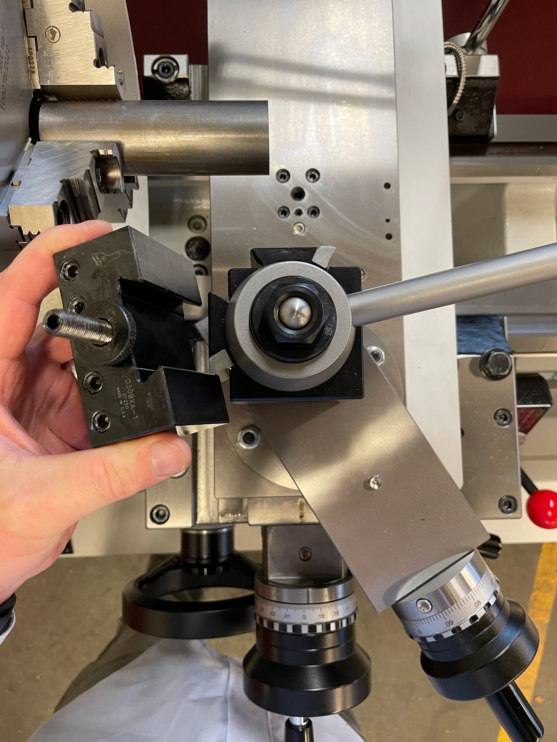
Step 2: Load a right-handed turning tool onto the squared tool post.

Step 3: Calculate and set the proper spindle speed for the combination of cutting tool and material to be used.
Step 4: Set the quick-change gear box for the feed rate desired to travel across the face of the work.
Step 5: Turn the spindle on.
Step 5: Turn the spindle on.

Step 12: Engage the cross-slide power feed.
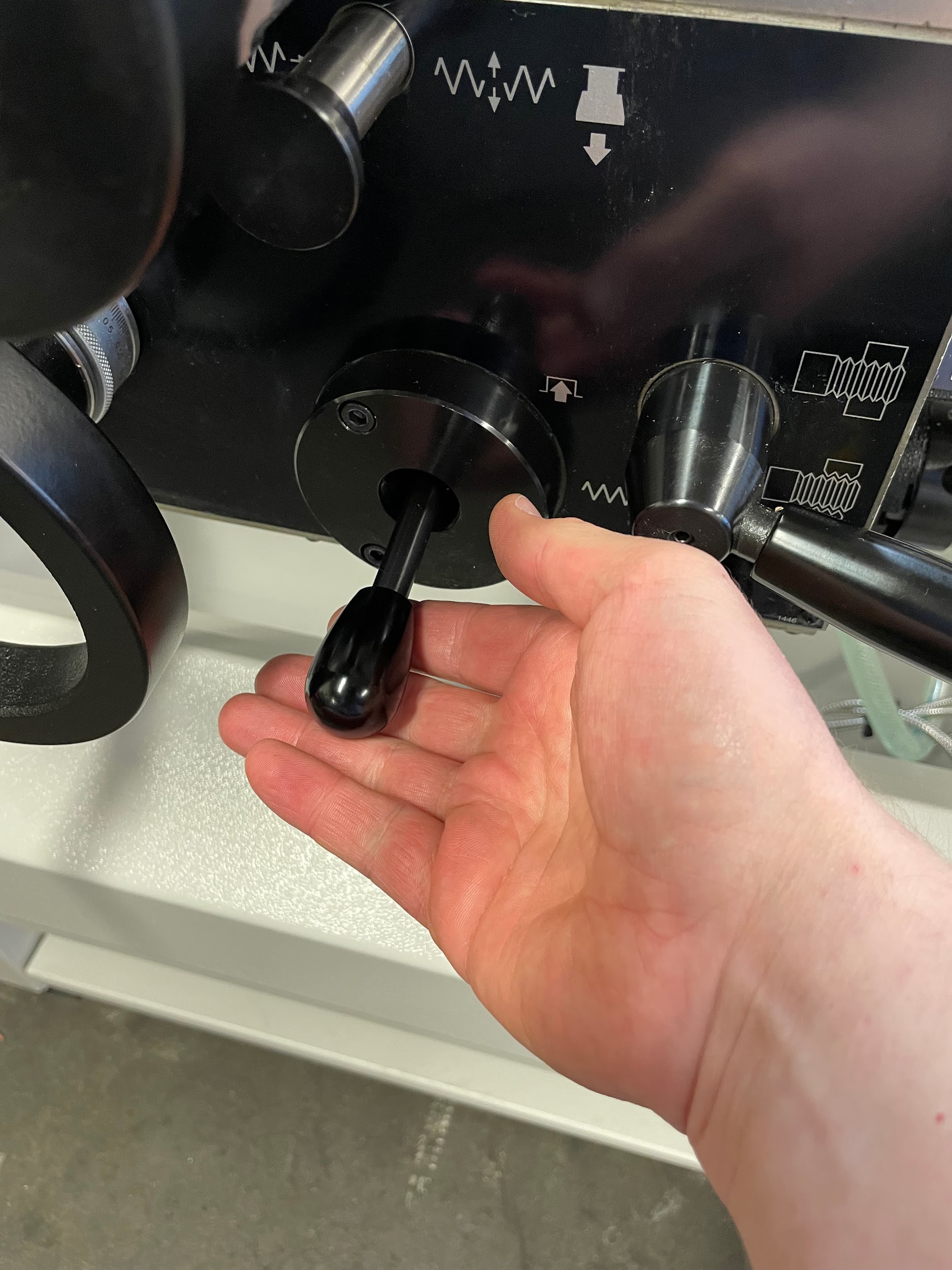
Step 5-13: Turn the spindle on. Manipulate the carriage and cross feed hand wheels to bring the cutting tool close to the face of the part and about 1/8″ inside of the outer diameter. Gently turn the carriage handwheel until the tip of the cutting tool starts touching the end of the work. Back the tool out past the outer diameter using the cross-slide handwheel. Adjust the graduated collar on the carriage handwheel to zero. Turn the carriage hand wheel in .005 or .010. to make an initial cut. Lock the carriage movement. Engage the cross-slide power feed. Allow the cutting tool to travel across the face of the work and disengage the power feed once the tool reaches the center.

Step 14: Inspect the face of the work and continue making successive cuts until the face has been cut all the way across.
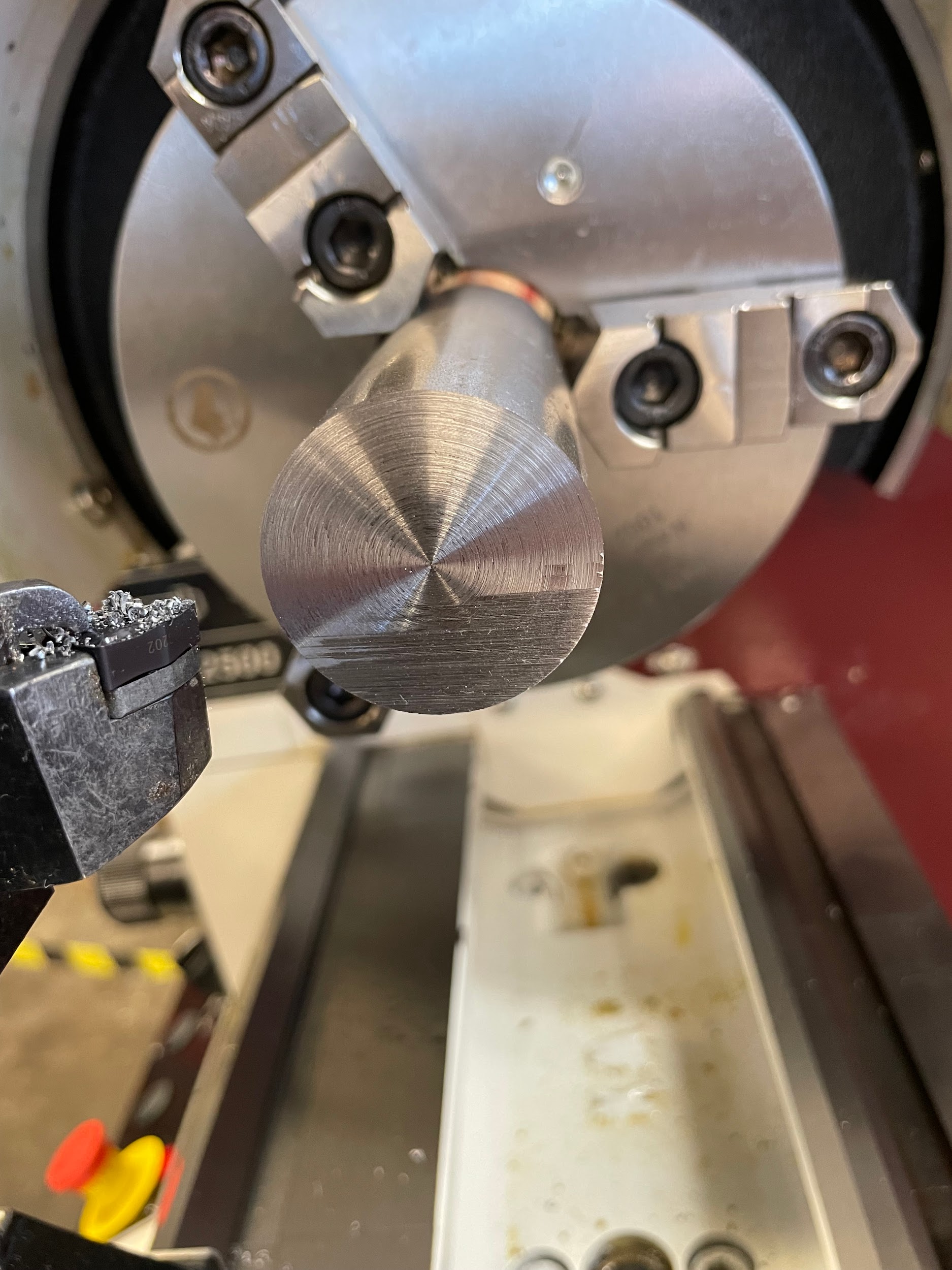
Step 14: Inspect the face of the work and continue making successive cuts until the face has been cut all the way across.

Step 16: Deburr the edge of the face with a file as the spindle is rotating. Hold the file handle in the left hand and the end of the file in the right hand to keep from reaching over the chuck.

Attributions
- Figure 10.95: Partially faced part by Micky R. Jennings, courtesy of Wenatchee Valley College, for WA Open ProfTech, © SBCTC, CC BY 4.0
- Figure 10.96: Loading a part by Micky R. Jennings, courtesy of Wenatchee Valley College, for WA Open ProfTech, © SBCTC, CC BY 4.0
- Video 10.32: Micky R. Jennings, courtesy of Wenatchee Valley College, for WA Open ProfTech, © SBCTC, CC BY 4.0
- Figure 10.97: Loading quick change toolholder by Micky R. Jennings, courtesy of Wenatchee Valley College, for WA Open ProfTech, © SBCTC, CC BY 4.0
- Video 10.33: Micky R. Jennings, courtesy of Wenatchee Valley College, for WA Open ProfTech, © SBCTC, CC BY 4.0
- Figure 10.98: Spindle speeds by Micky R. Jennings, courtesy of Wenatchee Valley College, for WA Open ProfTech, © SBCTC, CC BY 4.0
- Figure 10.99: Feed rates by Micky R. Jennings, courtesy of Wenatchee Valley College, for WA Open ProfTech, © SBCTC, CC BY 4.0
- Figure 10.100: Turning the spindle on by Micky R. Jennings, courtesy of Wenatchee Valley College, for WA Open ProfTech, © SBCTC, CC BY 4.0
- Video 10.34: Micky R. Jennings, courtesy of Wenatchee Valley College, for WA Open ProfTech, © SBCTC, CC BY 4.0
- Figure 10.101: Engaging the feed lever by Micky R. Jennings, courtesy of Wenatchee Valley College, for WA Open ProfTech, © SBCTC, CC BY 4.0
- Video 10.35: Micky R. Jennings, courtesy of Wenatchee Valley College, for WA Open ProfTech, © SBCTC, CC BY 4.0
- Figure 10.102: Partially faced part by Micky R. Jennings, courtesy of Wenatchee Valley College, for WA Open ProfTech, © SBCTC, CC BY 4.0
- Video 10.36: Micky R. Jennings, courtesy of Wenatchee Valley College, for WA Open ProfTech, © SBCTC, CC BY 4.0
- Video 10.37: Micky R. Jennings, courtesy of Wenatchee Valley College, for WA Open ProfTech, © SBCTC, CC BY 4.0
A term used on the lathe to describe the cutting across the end of a workpiece to make it flat, or to describe cutting the top of a part flat on a mill.
