10.12 Boring
Micky R. Jennings
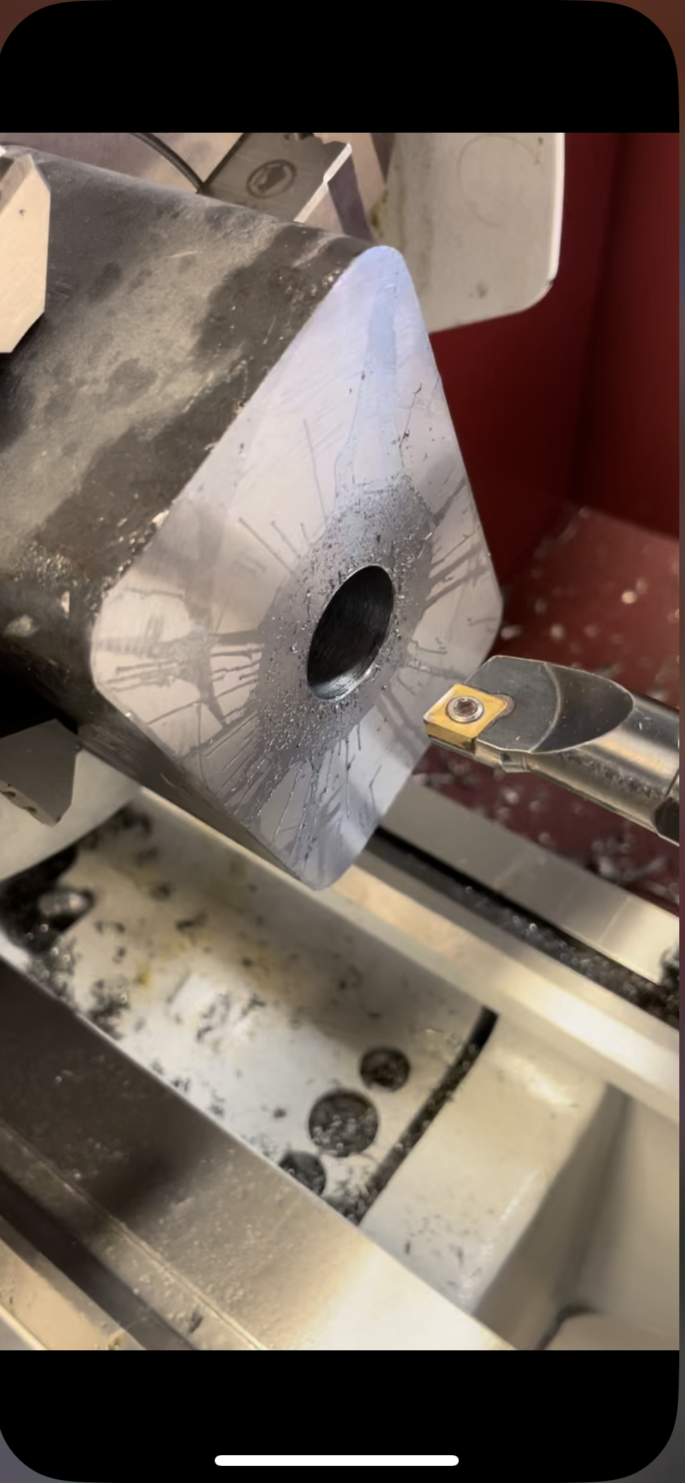
Boring is the process of enlarging a drilled hole in a manner similar to turning. Unlike turning, however, boring occurs on the inside of the part. Boring is performed with a tool known as a boring bar. Facing can also be performed with a boring bar. The length and diameter of the tool are critical considerations when setting up for a boring operation. Boring is generally more unstable than other turning operations and the operator must optimize the setup to reduce possible chatter. Boring is performed with multiple roughing cuts and at least one finishing cut.
Step by step process for boring:
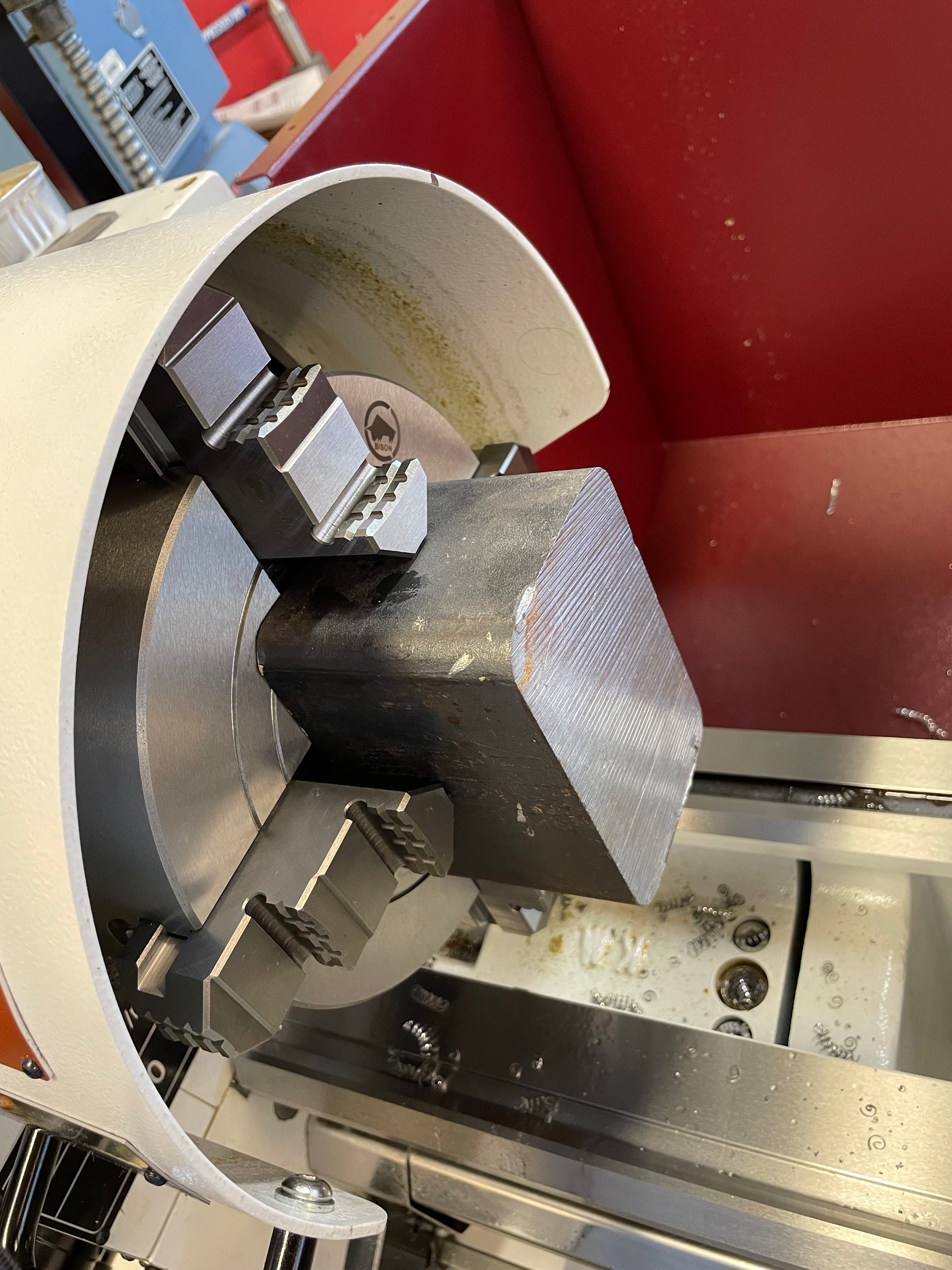
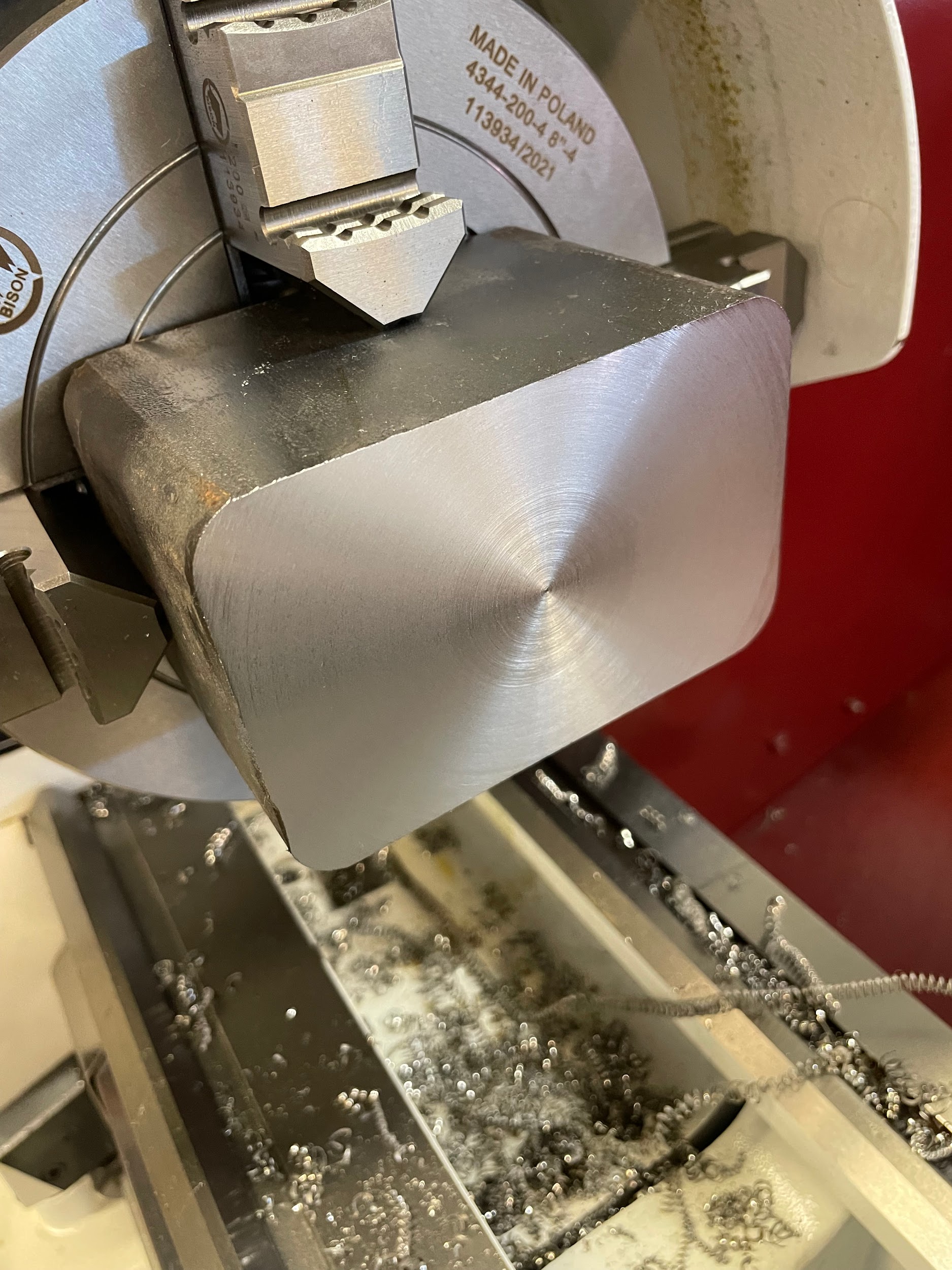
- Insert material into a chuck, dial in if necessary, and face.
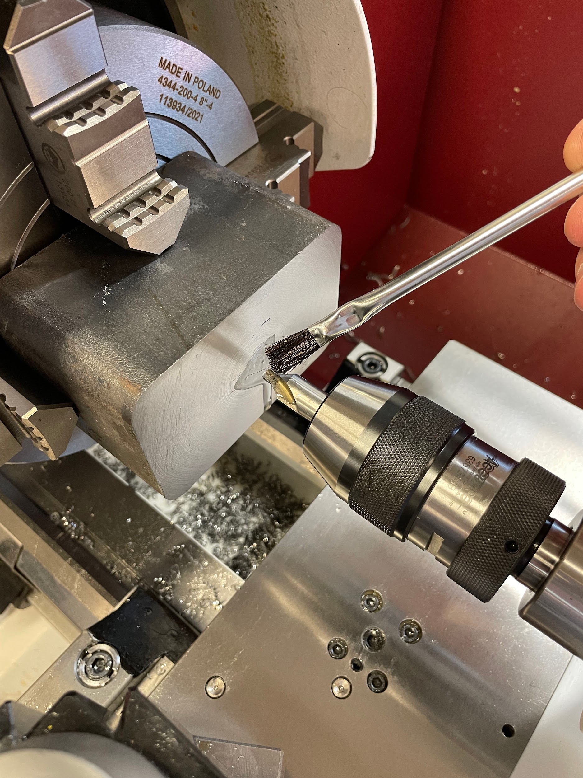
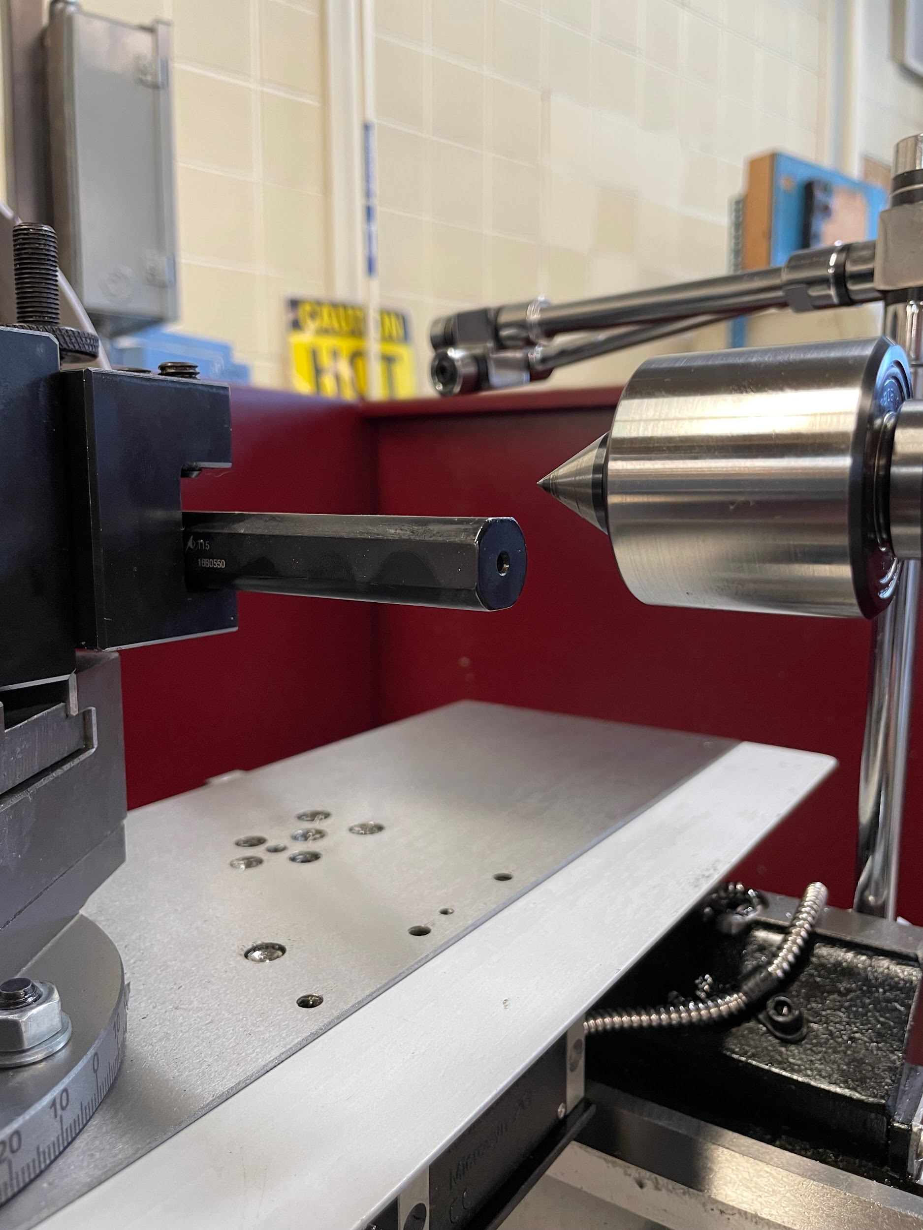
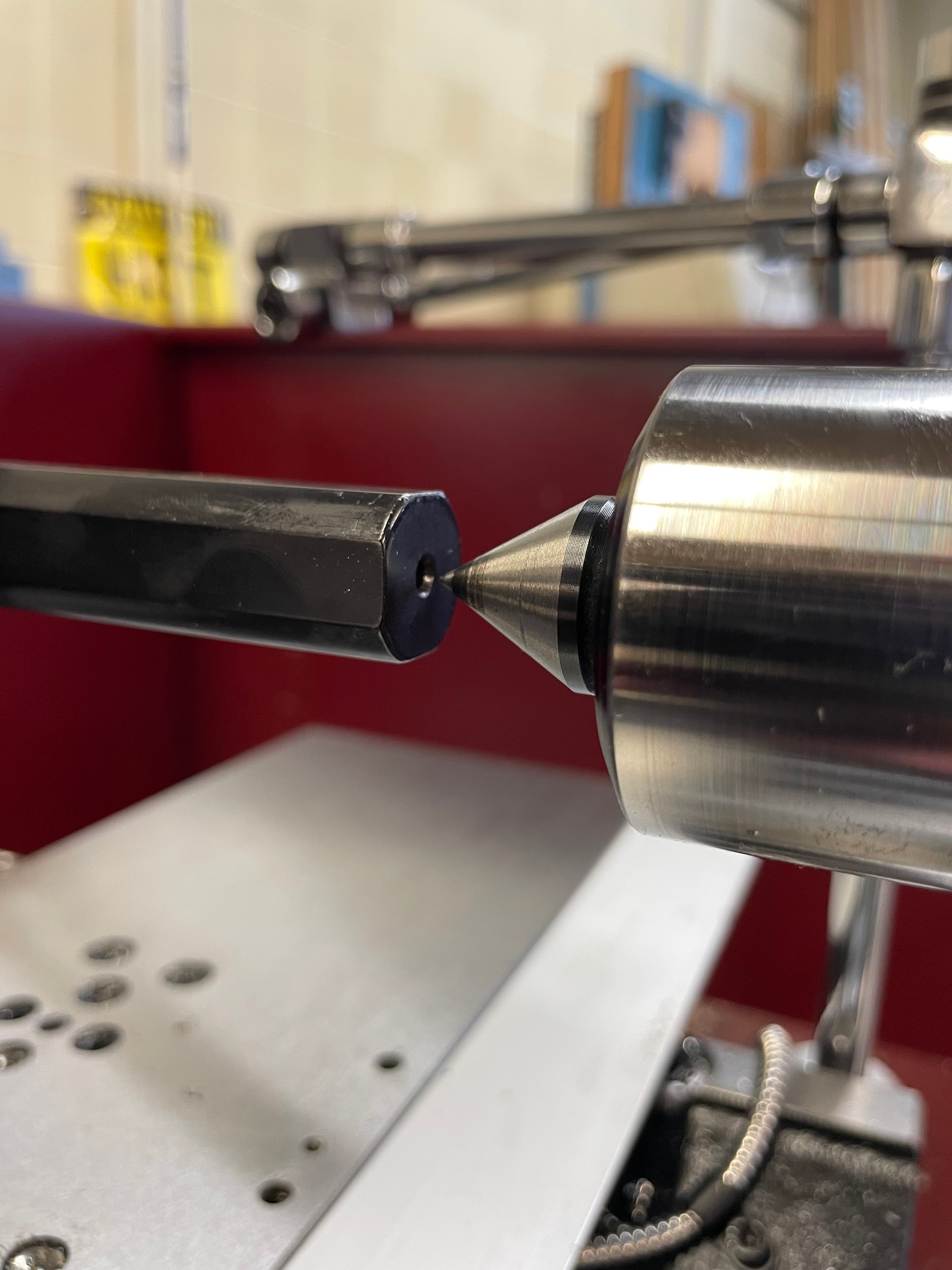
- Spot or center drill the part with the tailstock.
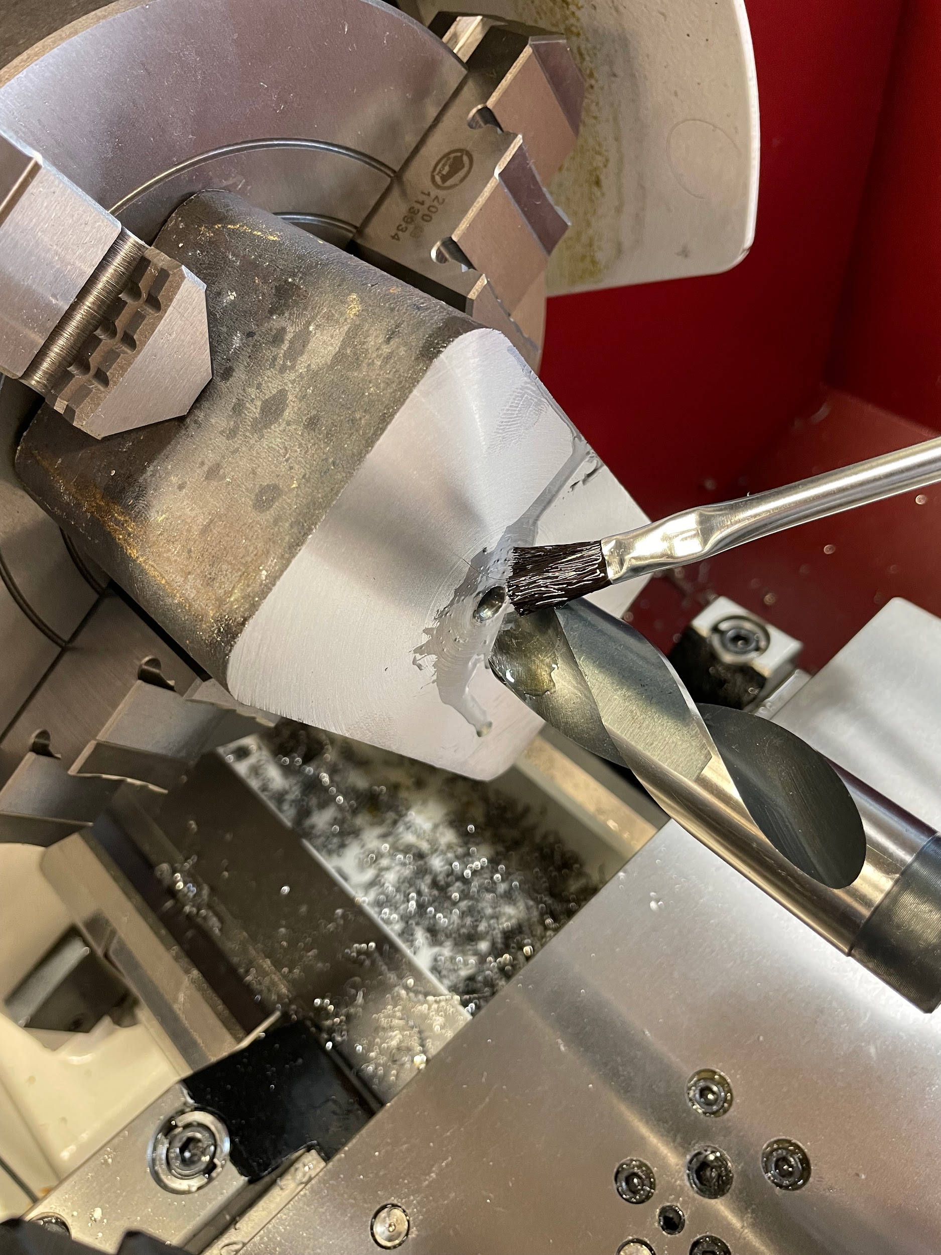
- Drill a hole large enough for the boring bar to fit inside. The insert offset can be measured and then added to the diameter of the to calculate the diameter required before boring. Sometimes this information is printed on the side of the boring bar.
- Load a boring bar into a tool holder and set the tool height. Make sure to only stick the bar out slightly longer than the depth required for the bored hole (approximately 1/8″).
- Select a spindle speed and feed rate for the boring operation. Calculate the spindle speed based on the diameter of the finished bore.
- Put layout dye on the boring bar at the approximate depth of the bored hole.
- Using odd legged calipers, scribe a precision depth gage line from the tip of the boring bar on the shank.
- Oil part if necessary.
- Turn the spindle on.
- Touch the boring bar off on the face of the part and set the graduated collar on the carriage hand wheel to zero.
- Touch the boring bar off on the inside of the bore and set the graduated collar on the cross-slide to zero.
- Pull the bar out of the hole and set an initial depth for the first cut.
- Engage the carriage feed lever and watch as the bar continues into the work, disengaging when the face of the work reaches 1/8″ from the scribed line on the bar.
- Take the remaining material out by hand while reading the graduated collar for accurate depth.
- Continue to make successive cuts until bore diameter is reached.
- Deburr opening of bored hole.
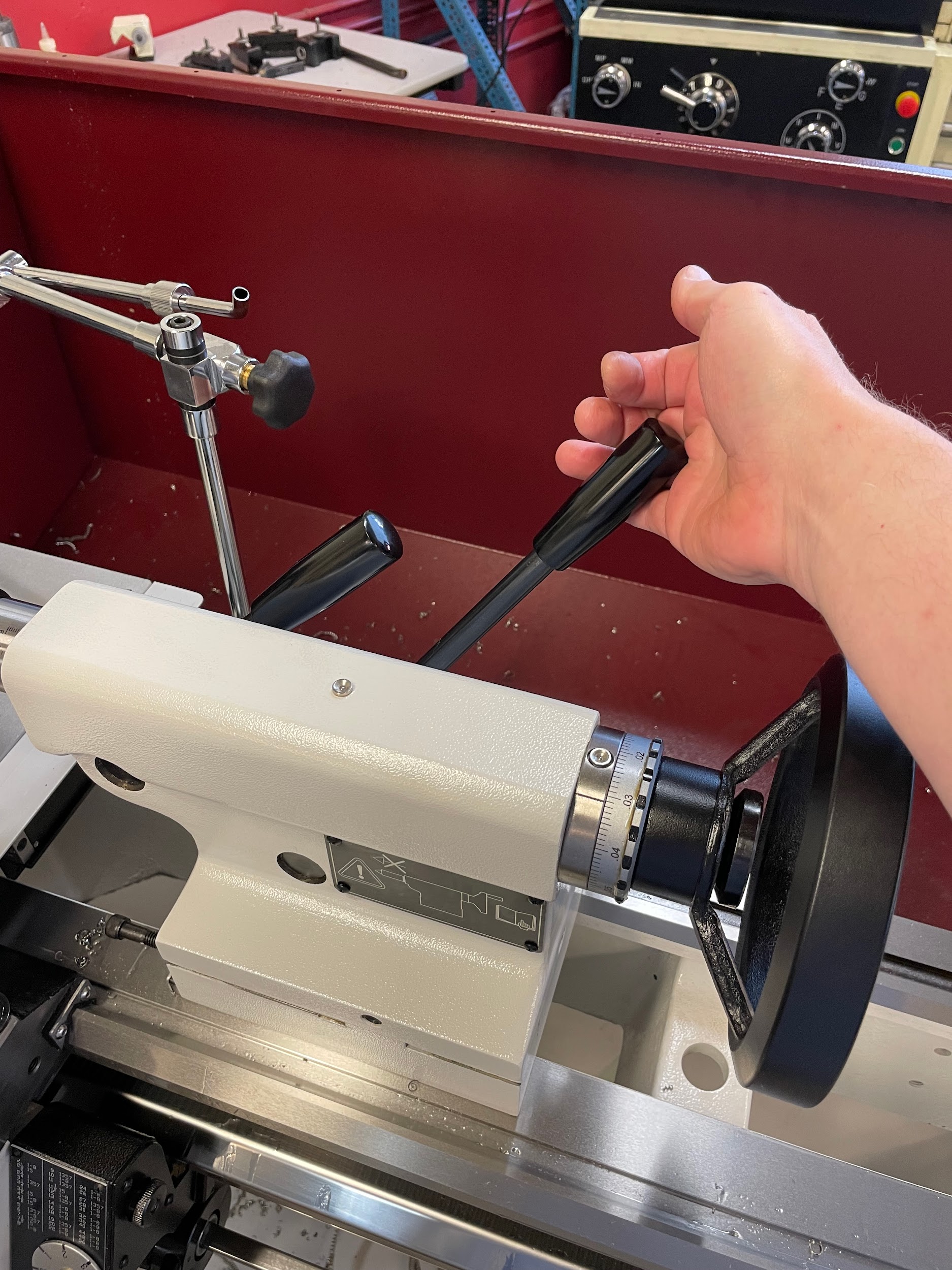
Step 1: Insert material into a chuck, dial in if necessary, and face.
Step 1: Insert material into a chuck, dial in if necessary, and face.

Step 1: Insert material into a chuck, dial in if necessary, and face.

Step 1: Insert material into a chuck, dial in if necessary, and face.
Step 1: Insert material into a chuck, dial in if necessary, and face.

Step 1: Insert material into a chuck, dial in if necessary, and face.
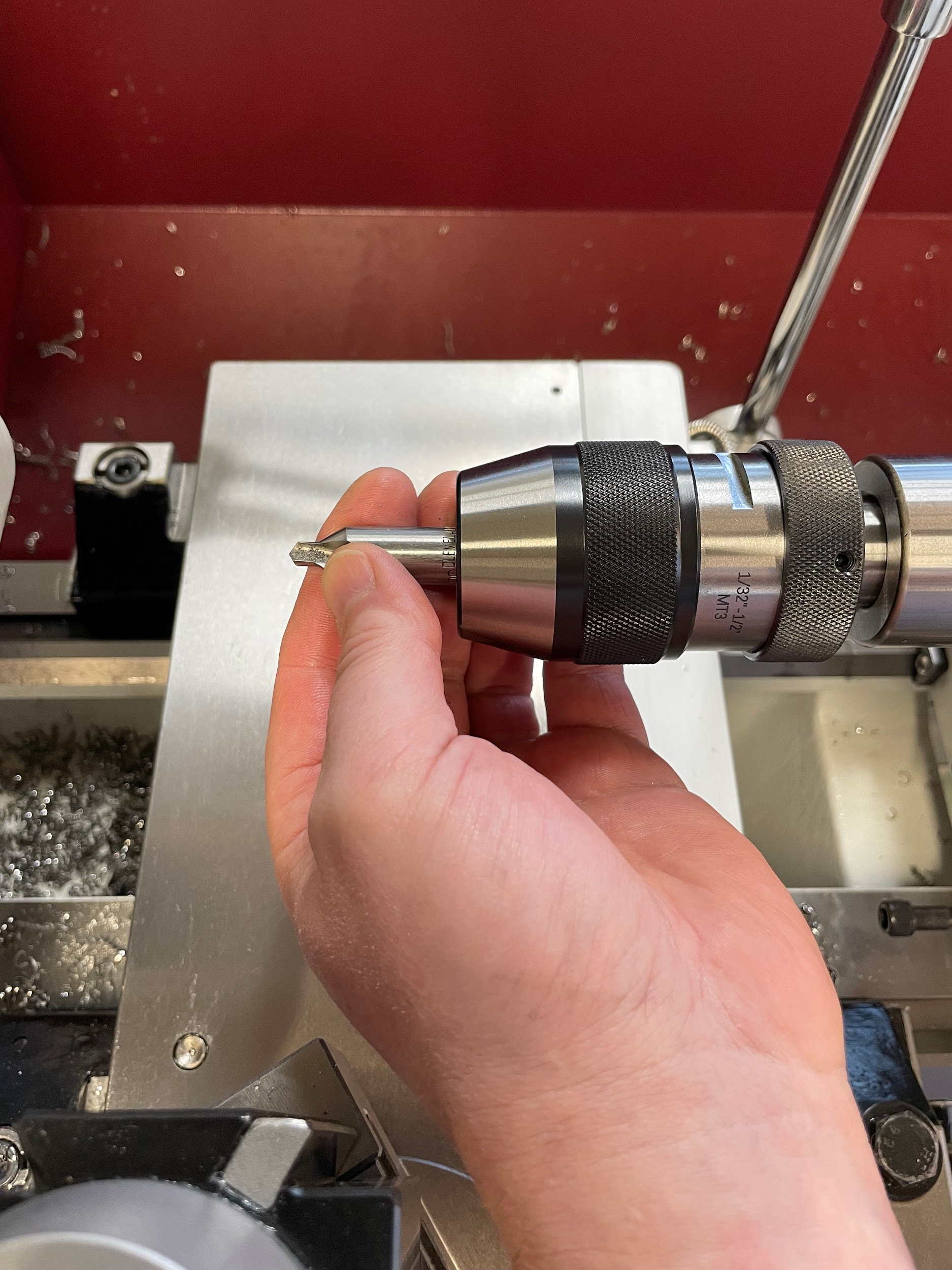
Step 2: Spot or center drill the part with the tailstock.

Step 2: Spot or center drill the part with the tailstock.
Step 2: Spot or center drill the part with the tailstock.
Step 2: Spot or center drill the part with the tailstock.

Step 2: Spot or center drill the part with the tailstock.

Step 2: Spot or center drill the part with the tailstock.
Step 2: Spot or center drill the part with the tailstock.

Step 3: Drill a hole large enough for the boring bar to fit inside. The insert offset can be measured and then added to the diameter of the to calculate the diameter required before boring. Sometimes this information is printed on the side of the boring bar.

Step 3: Drill a hole large enough for the boring bar to fit inside. The insert offset can be measured and then added to the diameter of the to calculate the diameter required before boring. Sometimes this information is printed on the side of the boring bar.

Step 3: Drill a hole large enough for the boring bar to fit inside. The insert offset can be measured and then added to the diameter of the to calculate the diameter required before boring. Sometimes this information is printed on the side of the boring bar.
Step 3: Drill a hole large enough for the boring bar to fit inside. The insert offset can be measured and then added to the diameter of the to calculate the diameter required before boring. Sometimes this information is printed on the side of the boring bar.”

Step 4: Load a boring bar into a tool holder and set the tool height. Make sure to only stick the bar out slightly longer than the depth required for the bored hole (approximately 1/8″).
Step 4: Load a boring bar into a tool holder and set the tool height. Make sure to only stick the bar out slightly longer than the depth required for the bored hole (approximately 1/8″).
Step 8: Oil part if necessary.

Step 10: Touch the boring bar off on the face of the part and set the graduated collar on the carriage hand wheel to zero.

Step 13: Engage the carriage feed lever and watch as the bar continues into the work, disengaging when the face of the work reaches 1/8″ from the scribed line on the bar.

Step 13: Engage the carriage feed lever and watch as the bar continues into the work, disengaging when the face of the work reaches 1/8″ from the scribed line on the bar.

Attributions
- Figure 10.109: Boring by Micky R. Jennings, courtesy of Wenatchee Valley College, for WA Open ProfTech, © SBCTC, CC BY 4.0
- Figure 10.110: Prepped for boring by Micky R. Jennings, courtesy of Wenatchee Valley College, for WA Open ProfTech, © SBCTC, CC BY 4.0
- Video 10.43: Micky R. Jennings, courtesy of Wenatchee Valley College, for WA Open ProfTech, © SBCTC, CC BY 4.0
- Video 10.44: Micky R. Jennings, courtesy of Wenatchee Valley College, for WA Open ProfTech, © SBCTC, CC BY 4.0
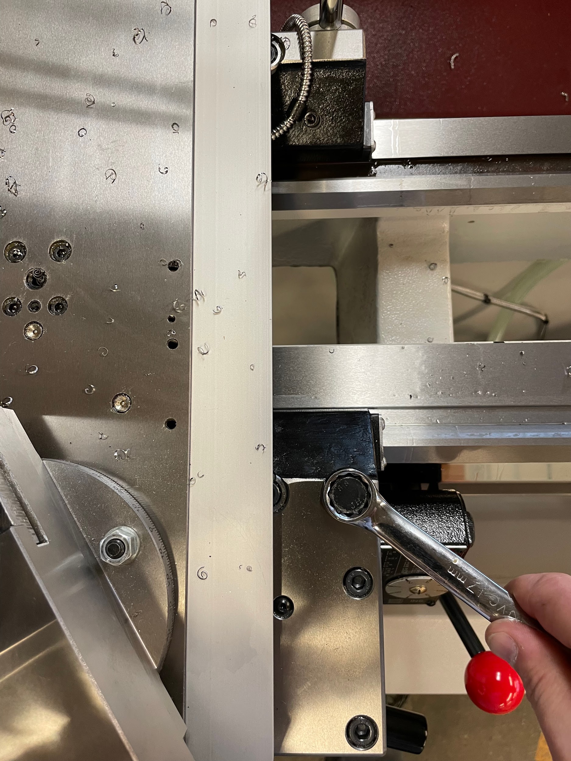
- Figure 10.111: Carriage locking by Micky R. Jennings, courtesy of Wenatchee Valley College, for WA Open ProfTech, © SBCTC, CC BY 4.0
- Video 10.45: Micky R. Jennings, courtesy of Wenatchee Valley College, for WA Open ProfTech, © SBCTC, CC BY 4.0
- Figure 10.112: Faced by Micky R. Jennings, courtesy of Wenatchee Valley College, for WA Open ProfTech, © SBCTC, CC BY 4.0
- Video 10.46: Micky R. Jennings, courtesy of Wenatchee Valley College, for WA Open ProfTech, © SBCTC, CC BY 4.0
- Figure 10.113: Tailstock lock by Micky R. Jennings, courtesy of Wenatchee Valley College, for WA Open ProfTech, © SBCTC, CC BY 4.0
- Figure 10.114: Loading the center drill by Micky R. Jennings, courtesy of Wenatchee Valley College, for WA Open ProfTech, © SBCTC, CC BY 4.0
- Video 10.47: Micky R. Jennings, courtesy of Wenatchee Valley College, for WA Open ProfTech, © SBCTC, CC BY 4.0
- Video 10.48: Micky R. Jennings, courtesy of Wenatchee Valley College, for WA Open ProfTech, © SBCTC, CC BY 4.0
- Figure 10.115: Applying cutting oil by Micky R. Jennings, courtesy of Wenatchee Valley College, for WA Open ProfTech, © SBCTC, CC BY 4.0
- Video 10.49: Micky R. Jennings, courtesy of Wenatchee Valley College, for WA Open ProfTech, © SBCTC, CC BY 4.0
- Video 10.50: Micky R. Jennings, courtesy of Wenatchee Valley College, for WA Open ProfTech, © SBCTC, CC BY 4.0
- Video 10.51: Micky R. Jennings, courtesy of Wenatchee Valley College, for WA Open ProfTech, © SBCTC, CC BY 4.0
- Figure 10.116: Applying cutting oil to drill by Micky R. Jennings, courtesy of Wenatchee Valley College, for WA Open ProfTech, © SBCTC, CC BY 4.0
- Video 10.52: Micky R. Jennings, courtesy of Wenatchee Valley College, for WA Open ProfTech, © SBCTC, CC BY 4.0
- Figure 10.117: Low boring bar by Micky R. Jennings, courtesy of Wenatchee Valley College, for WA Open ProfTech, © SBCTC, CC BY 4.0
- Figure 10.118: Correct boring bar height by Micky R. Jennings, courtesy of Wenatchee Valley College, for WA Open ProfTech, © SBCTC, CC BY 4.0
- Video 10.53: Micky R. Jennings, courtesy of Wenatchee Valley College, for WA Open ProfTech, © SBCTC, CC BY 4.0
- Video 10.54: Micky R. Jennings, courtesy of Wenatchee Valley College, for WA Open ProfTech, © SBCTC, CC BY 4.0
- Video 10.55: Micky R. Jennings, courtesy of Wenatchee Valley College, for WA Open ProfTech, © SBCTC, CC BY 4.0
- Video 10.56: Micky R. Jennings, courtesy of Wenatchee Valley College, for WA Open ProfTech, © SBCTC, CC BY 4.0
A cutting operation that uses a single point cutting tool (boring bar) to produce an internal conical, or cylindrical feature by enlarging an existing opening in a workpiece.
