10.14 Radius Cutting
Micky R. Jennings
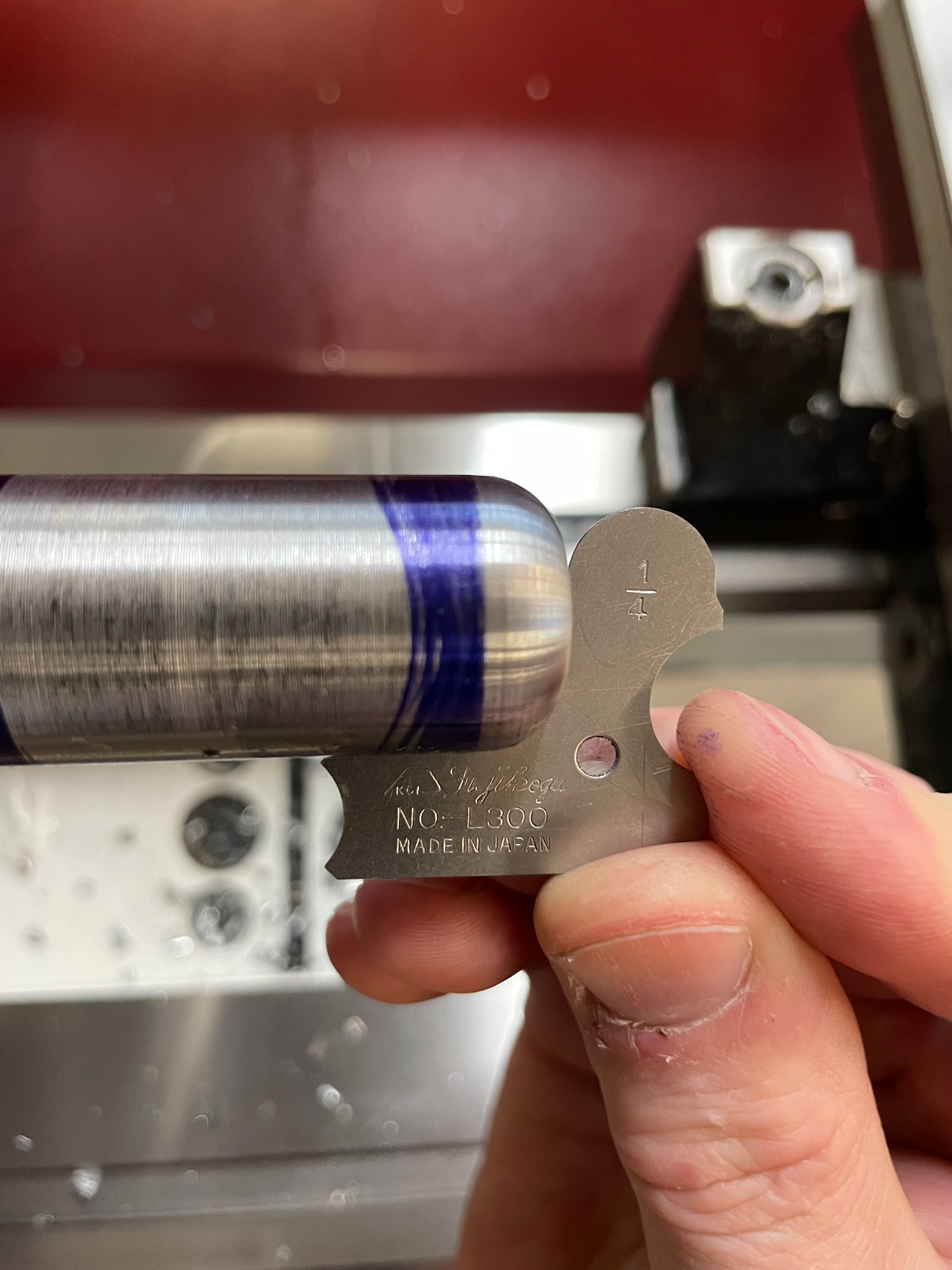
Figure 10.129 A hand holds a ¼” radius gauge, measuring the convex radius at the end of the part. / Image Credit: Micky R. Jennings, courtesy of Wenatchee Valley College, CC BY 4.0
Radius cutting refers to the process of creating either a concave or convex radius on the workpiece using the lathe. There are a couple of ways to create a radius on a lathe. One method entails using a radius cutting attachment. Another method would be using form tools. Both approaches work well, but using a radius cutting attachment may be more time-consuming and costly in most cases. Buying a custom ground form tool may also be out of the budget for some jobs. If a shop has radius measuring gages, HSS, and a pedestal grinder, simple radius form tool creation is a possibility. For standard 90 or 180 degree radii, ball end mills and milling radius cutters can be used with good results.
Step by step process for cutting a convex radius:
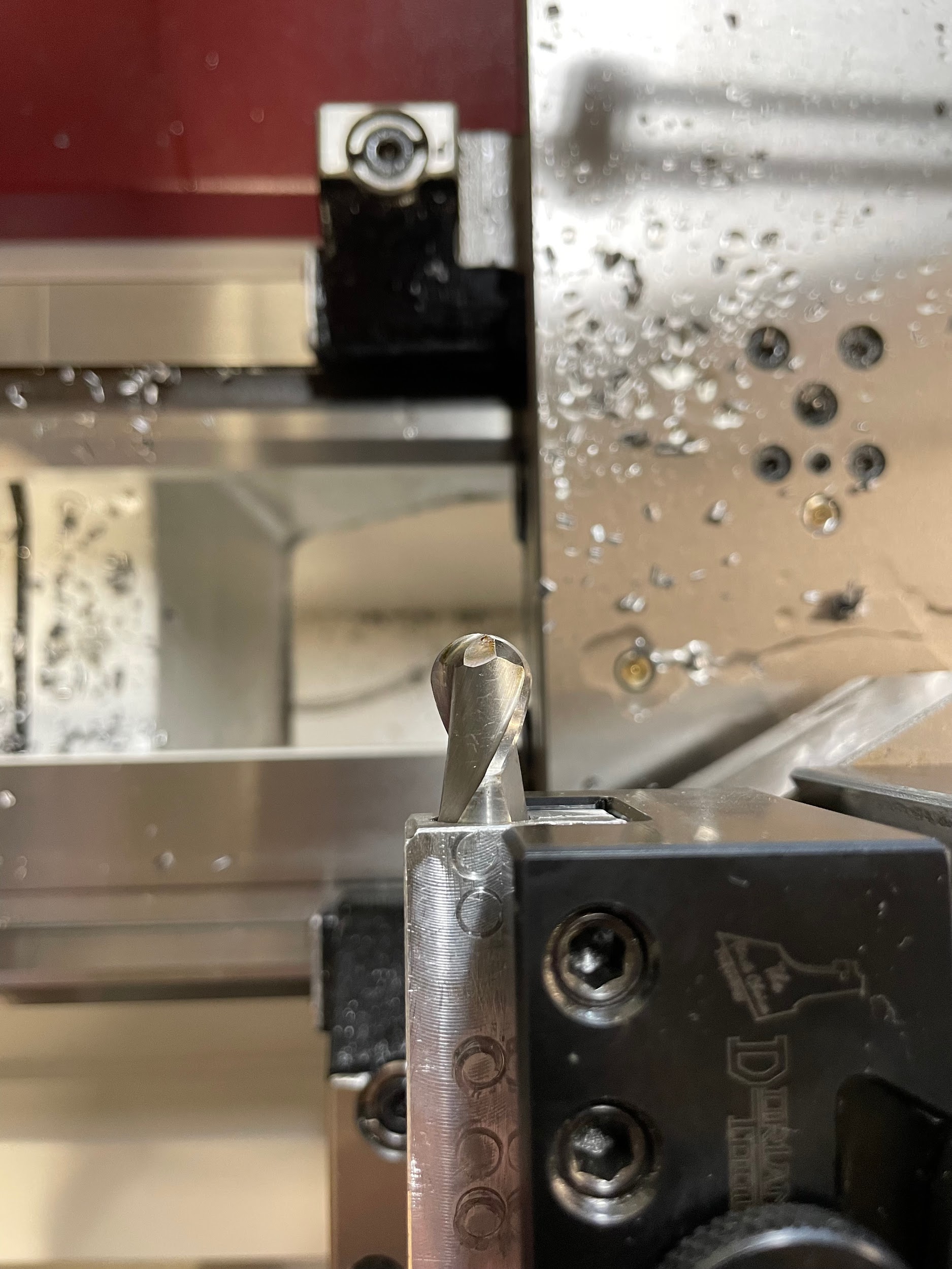
- Select a 90 degree radius cutting tool, install it in a tool holder on the tool post, and square it to the machine.
- Apply layout dye to the outside diameter and the face that will have the 90 degree radius.
- Calculate the spindle speed for the maximum diameter of the work the tool will contact. The spindle speed is generally 1/4 the speed for form turning to that of standard turning because of the amount of tool in contact with the work. The longer the linear length of cutting edge touching the work, the greater the chance for chatter to occur.
- Start the spindle.
- Touch the radial flat edge to the face of where the radius is to be.
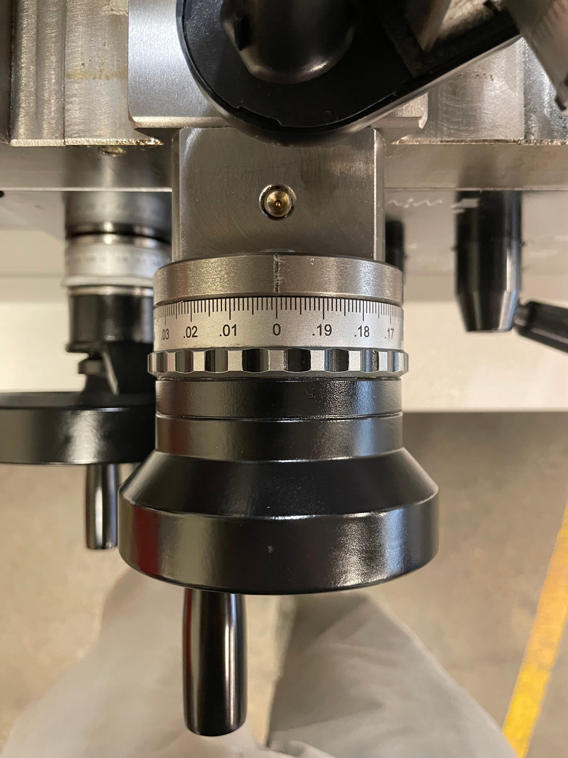
- Set the carriage handwheel to zero.
- Back the tool off the part.
- Touch the axial flat edge to the diameter of where the radius is to be.
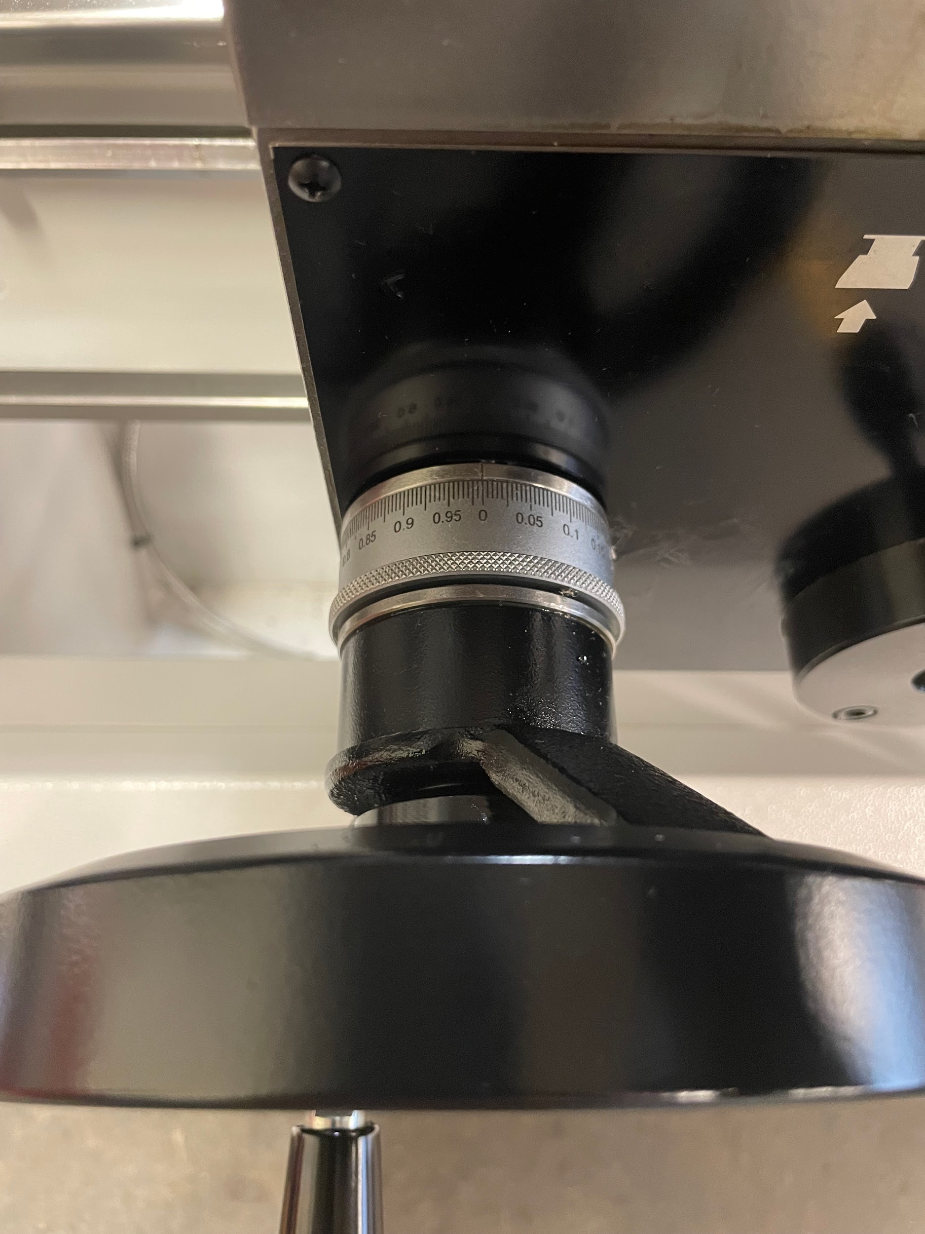
- Set the cross slide handwheel to zero.
- Back the tool off.
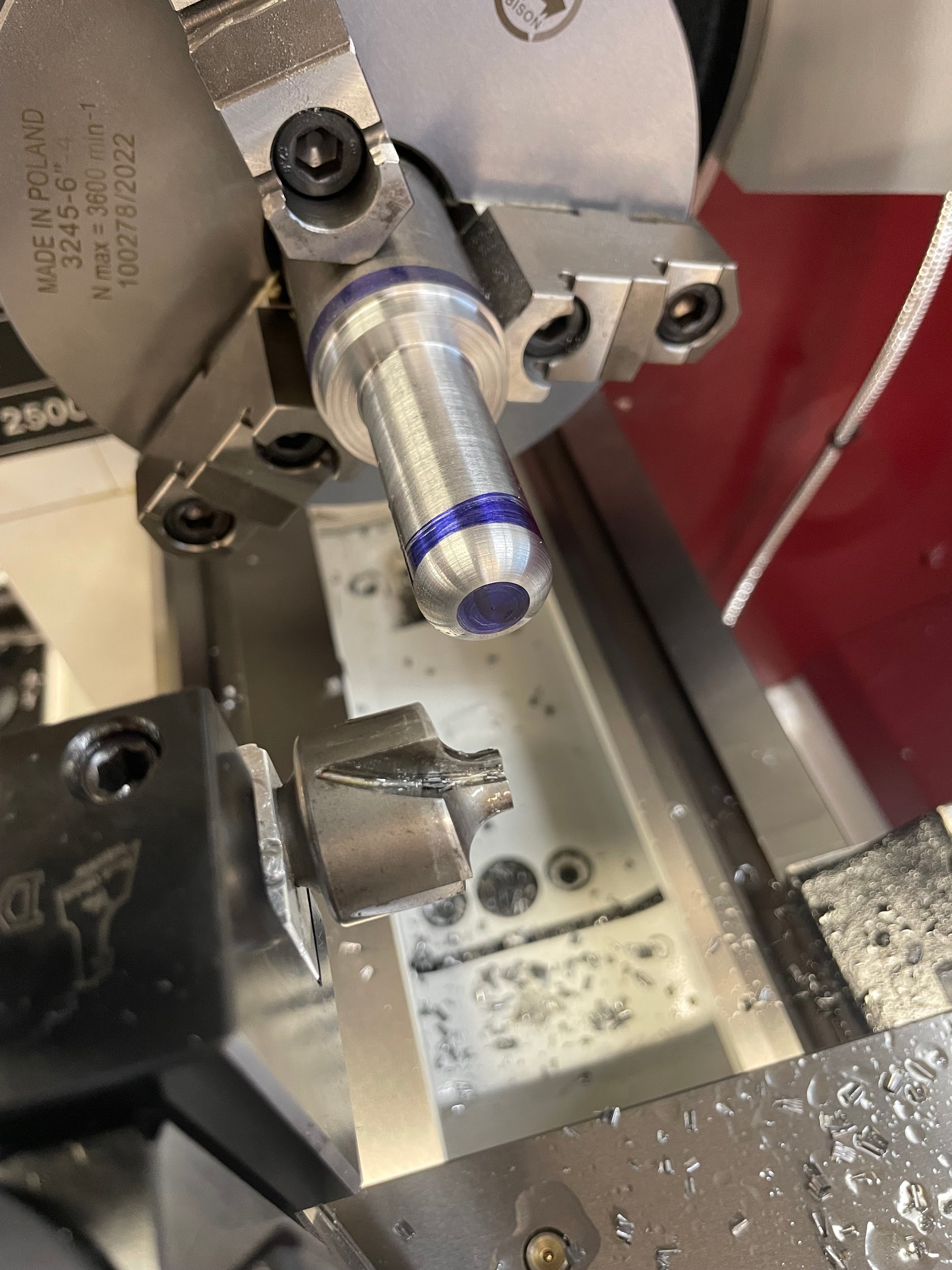
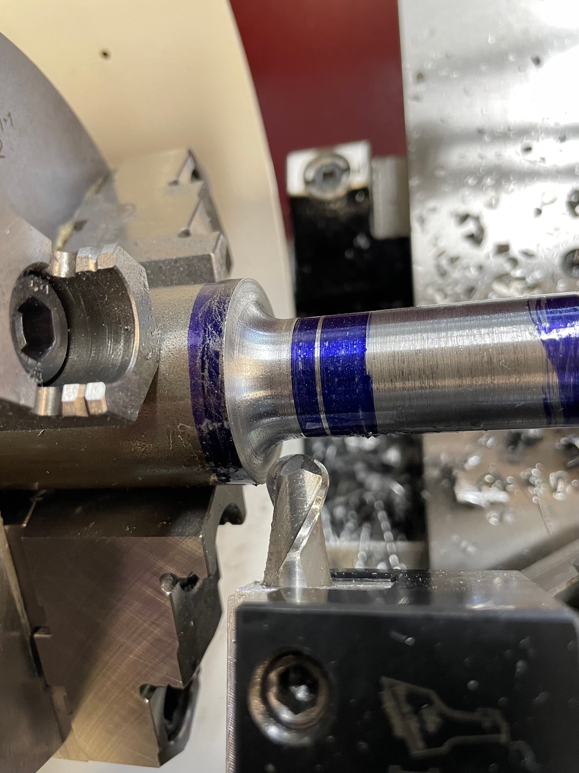
- Bring the center of the radius tool up to the corner of the part.
- Apply cutting oil.
- Gently work the tool in a little on the cross slide, then a little on the carriage. Back and forth with each until reaching the zero point on both hand wheels.
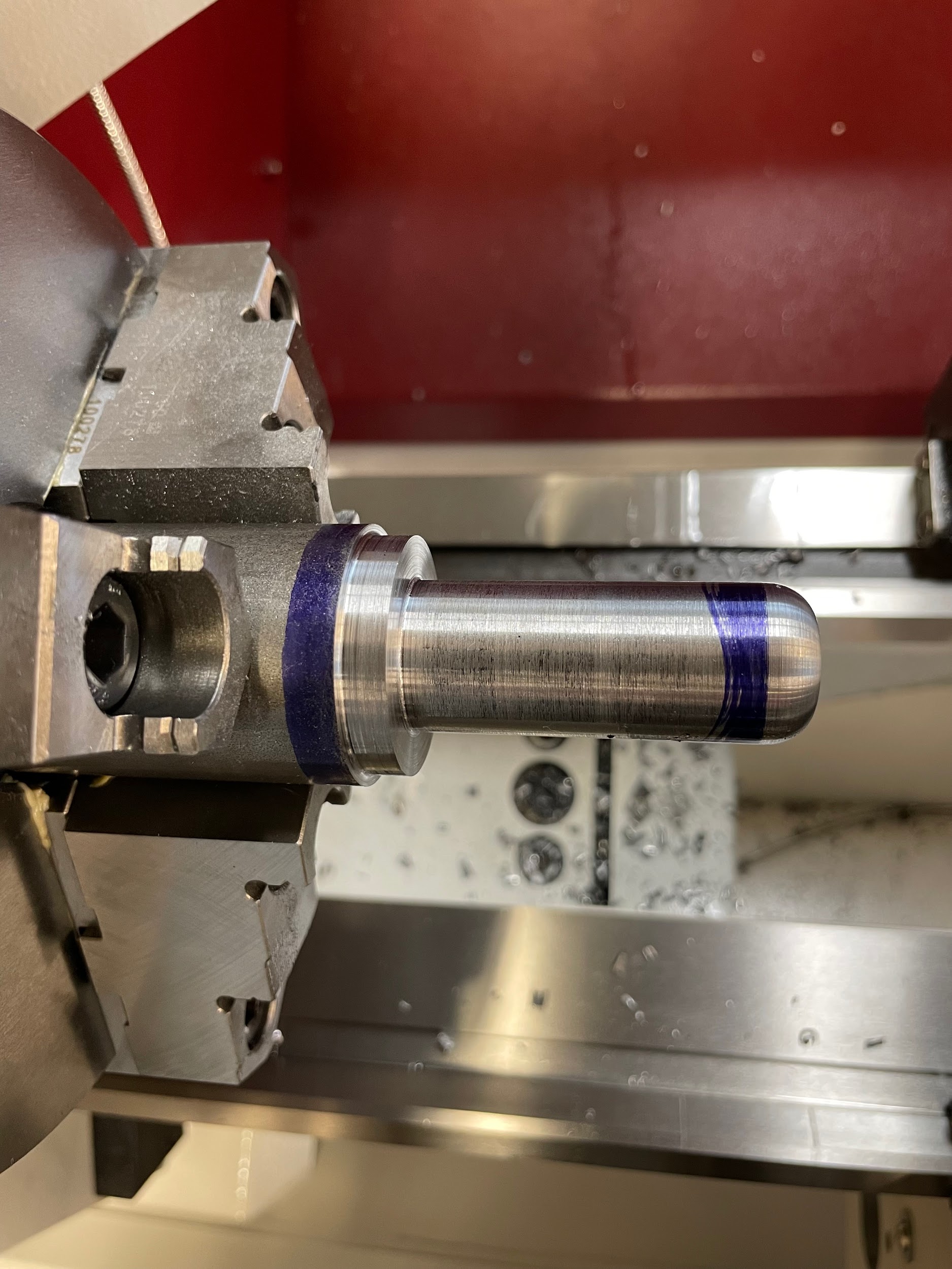
- Back the tool off and measure with a radius gage.
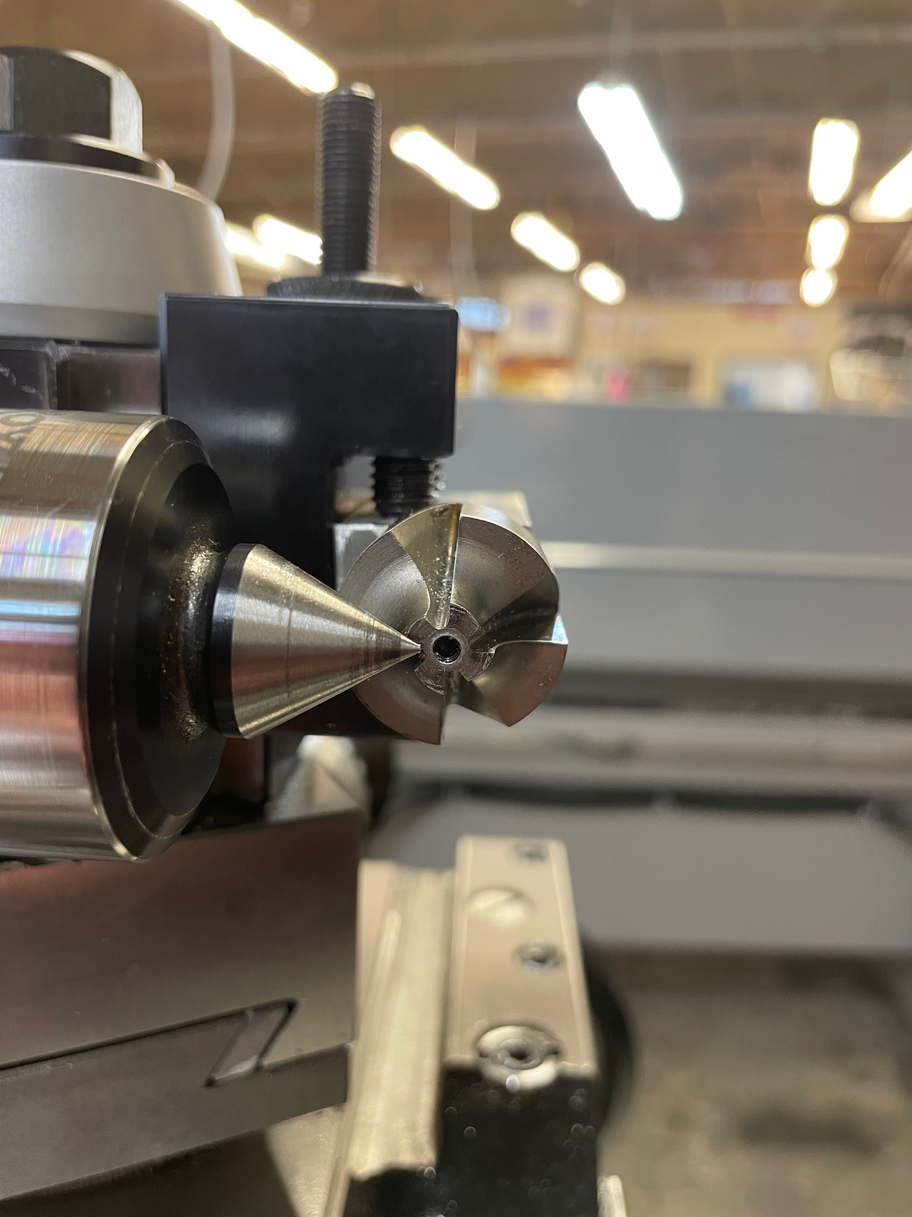
Step 1: Select a 90 degree radius cutting tool, install it in a tool holder on the tool post, and square it to the machine.
Step 1: Select a 90 degree radius cutting tool, install it in a tool holder on the tool post, and square it to the machine.
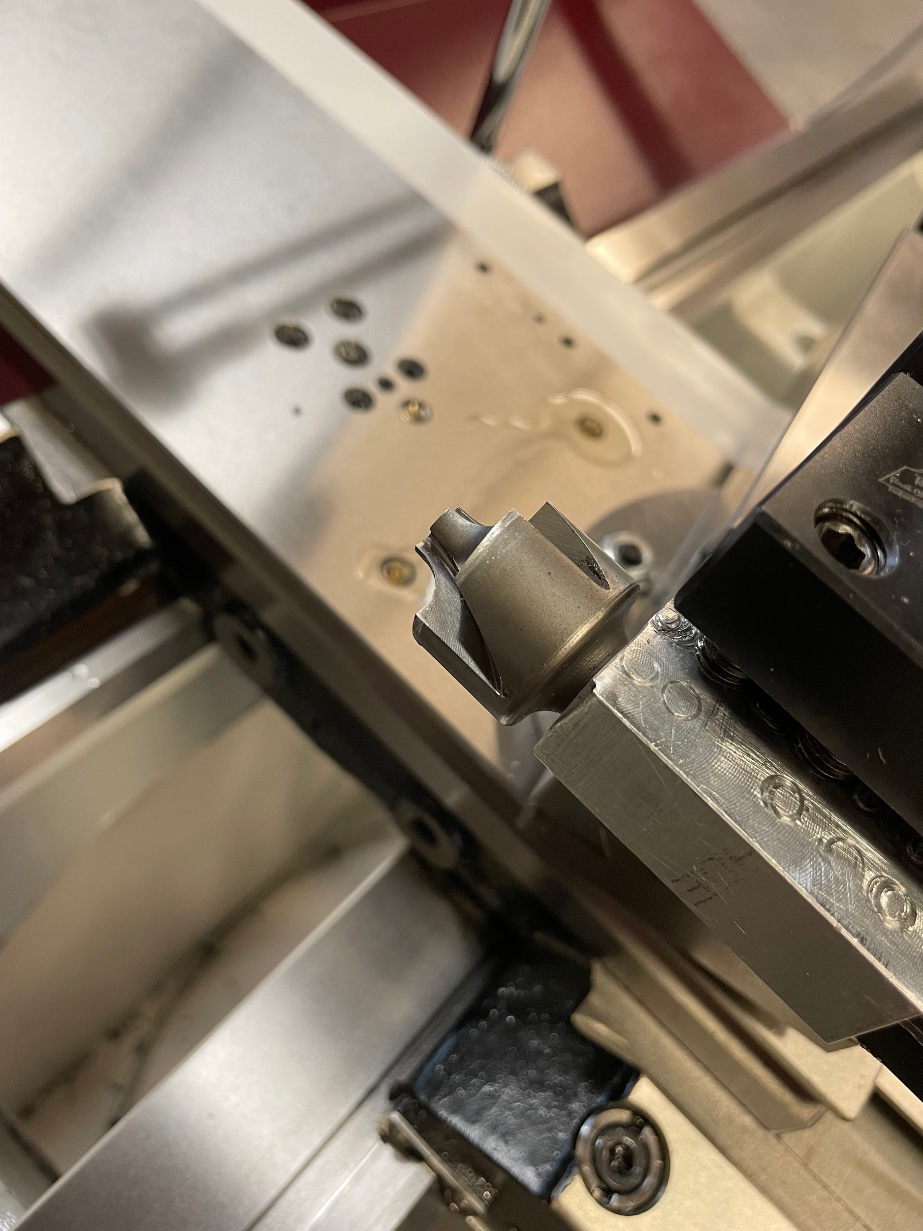
Step 1: Select a 90 degree radius cutting tool, install it in a tool holder on the tool post, and square it to the machine.
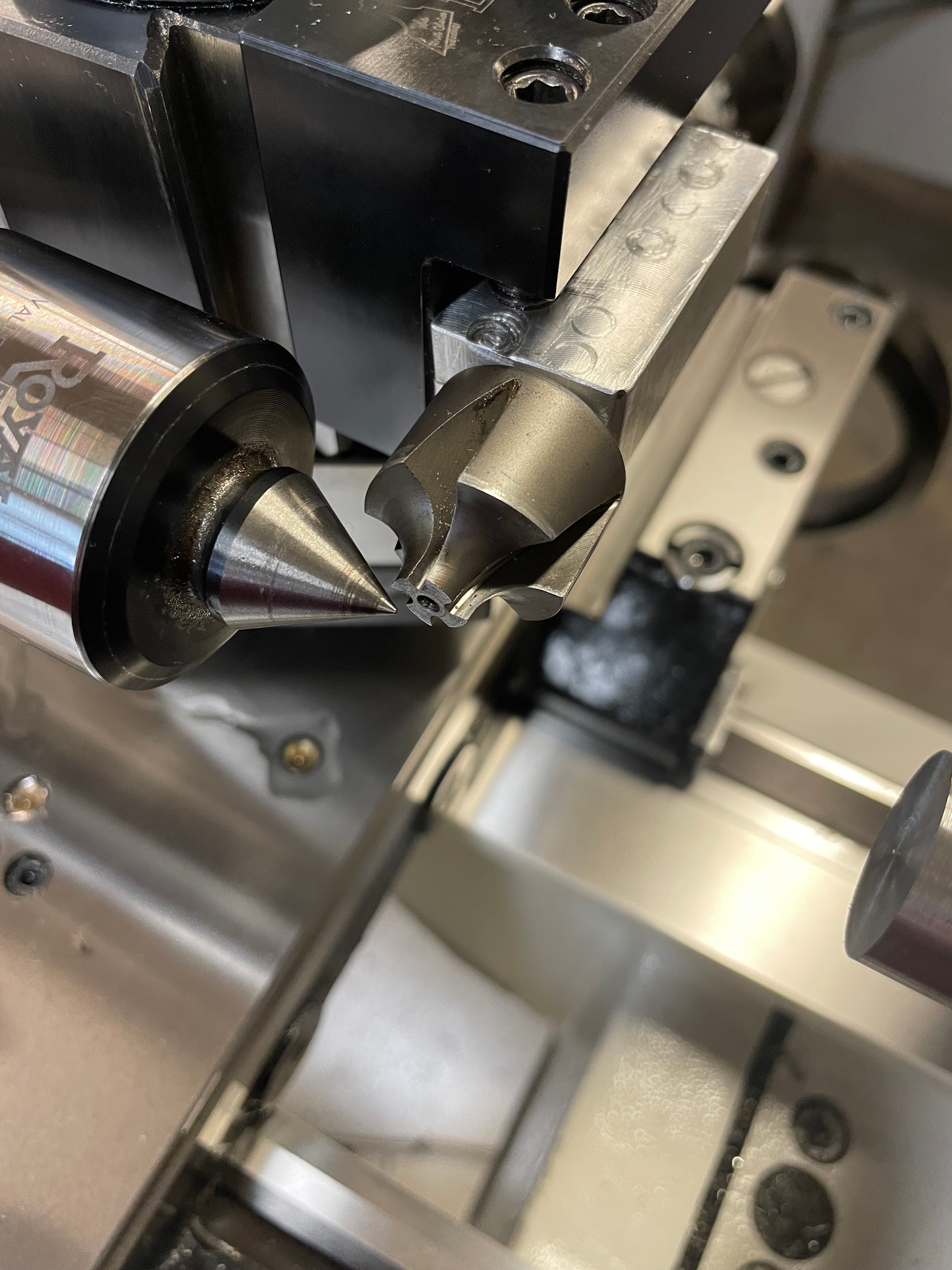
Step 1: Select a 90 degree radius cutting tool, install it in a tool holder on the tool post, and square it to the machine.
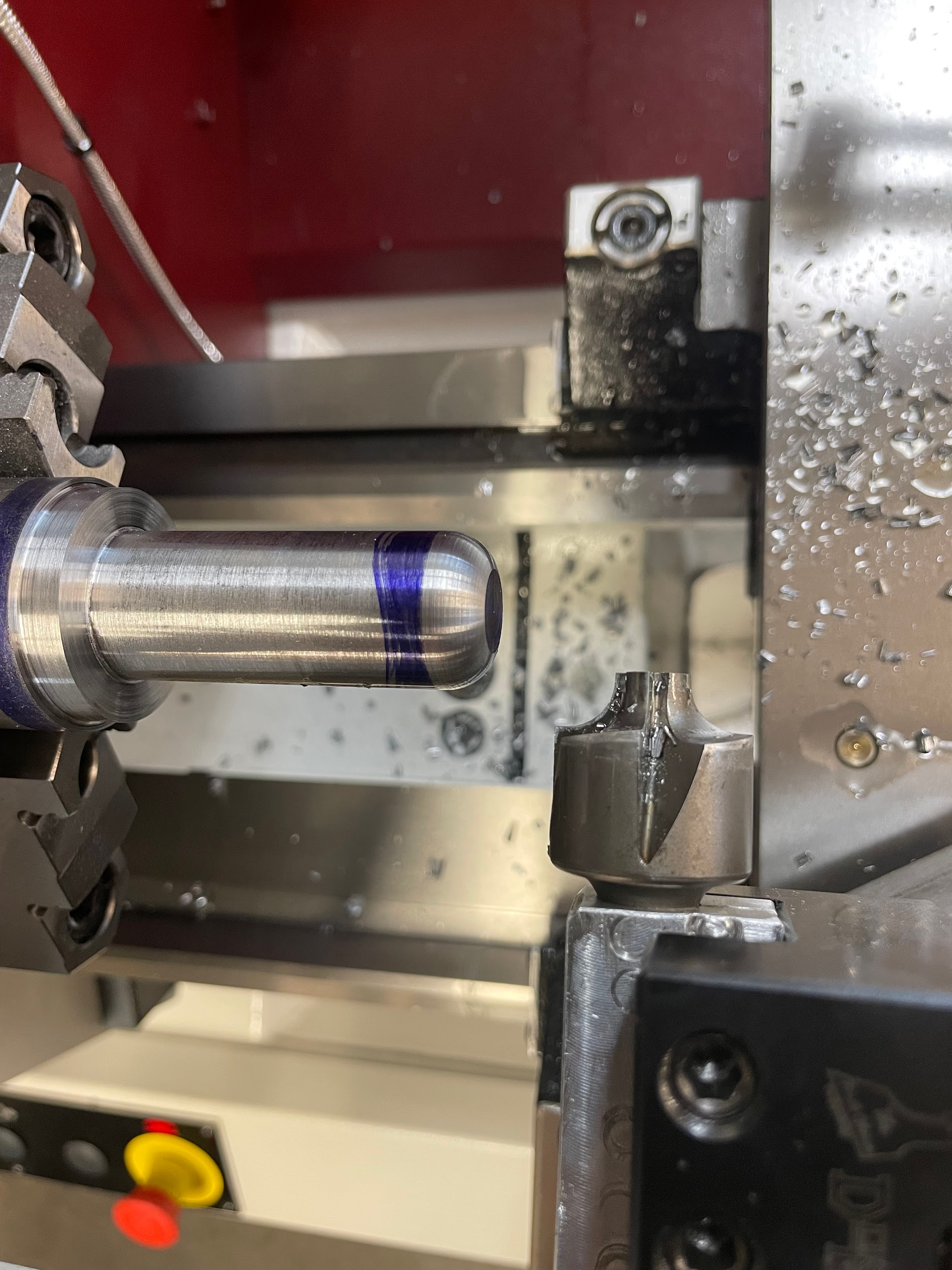
Step 2: Apply layout dye to the outside diameter and the face that will have the 90 degree radius.

Step 5: Touch the radial flat edge to the face of where the radius is to be.

Step 6: Set the carriage handwheel to zero.

Step 8: Touch the axial flat edge to the diameter of where the radius is to be.

Step 9: Set the cross-slide handwheel to zero.

Step 12: Apply cutting oil.

Step 13: Gently work the tool in a little on the cross-slide, then a little on the carriage. Back and forth with each until reaching the zero point on both hand wheels.

Step 13: Gently work the tool in a little on the cross slide, then a little on the carriage. Back and forth with each until reaching the zero point on both hand wheels.
Step 13: Gently work the tool in a little on the cross-slide, then a little on the carriage. Back and forth with each until reaching the zero point on both hand wheels.
Step 14: Back the tool off and measure with a radius gage.

Figure 10.140 A hand holds a ¼” radius gauge, measuring the convex radius at the end of the part./ Image Credit: Micky R. Jennings, courtesy of Wenatchee Valley College, CC BY 4.0
The following is the process for cutting a basic 90 degree concave radius. When turning a diameter that will have an internal radius up against a shoulder, the allowance of the radius must be accounted for. The steps below start with the basics of allowing for the extra material needed.
Step by step process for cutting a concave radius:
- Examine the print for the radius size.
- Calculate the step size that will be left in place of the radius. For instance, a 1/2″ radius would require a step of 1/2″ shorter in length, and 1″ larger in diameter to allow for the creation of the radius. Essentially, instead of making one rectangular shaped cut, two will be made.
- Rough and finish the largest diameter and full-length step.
- Rough and finish the smallest diameter and shortest length step.
- Select a 90 degree radius cutting tool, install it in a tool holder on the tool post, and square it to the machine.
- Apply layout dye to the outside diameter and the face that will have the 90 degree radius.
- Calculate the spindle speed for the maximum diameter of the work the tool will contact. The spindle speed is generally 1/4 the speed for form turning to that of standard turning because of the amount of tool in contact with the work. The longer the linear length of cutting edge touching the work, the greater the chance for chatter to occur.
- Start the spindle.
- Touch the radius tool to the finished diameter of where the radius will end.
- Set the cross-slide handwheel to zero.
- Back the tool off the part.
- Touch the radius tool to the finished shoulder of where the radius will end.
- Set the carriage handwheel to zero.
- Back the tool off.
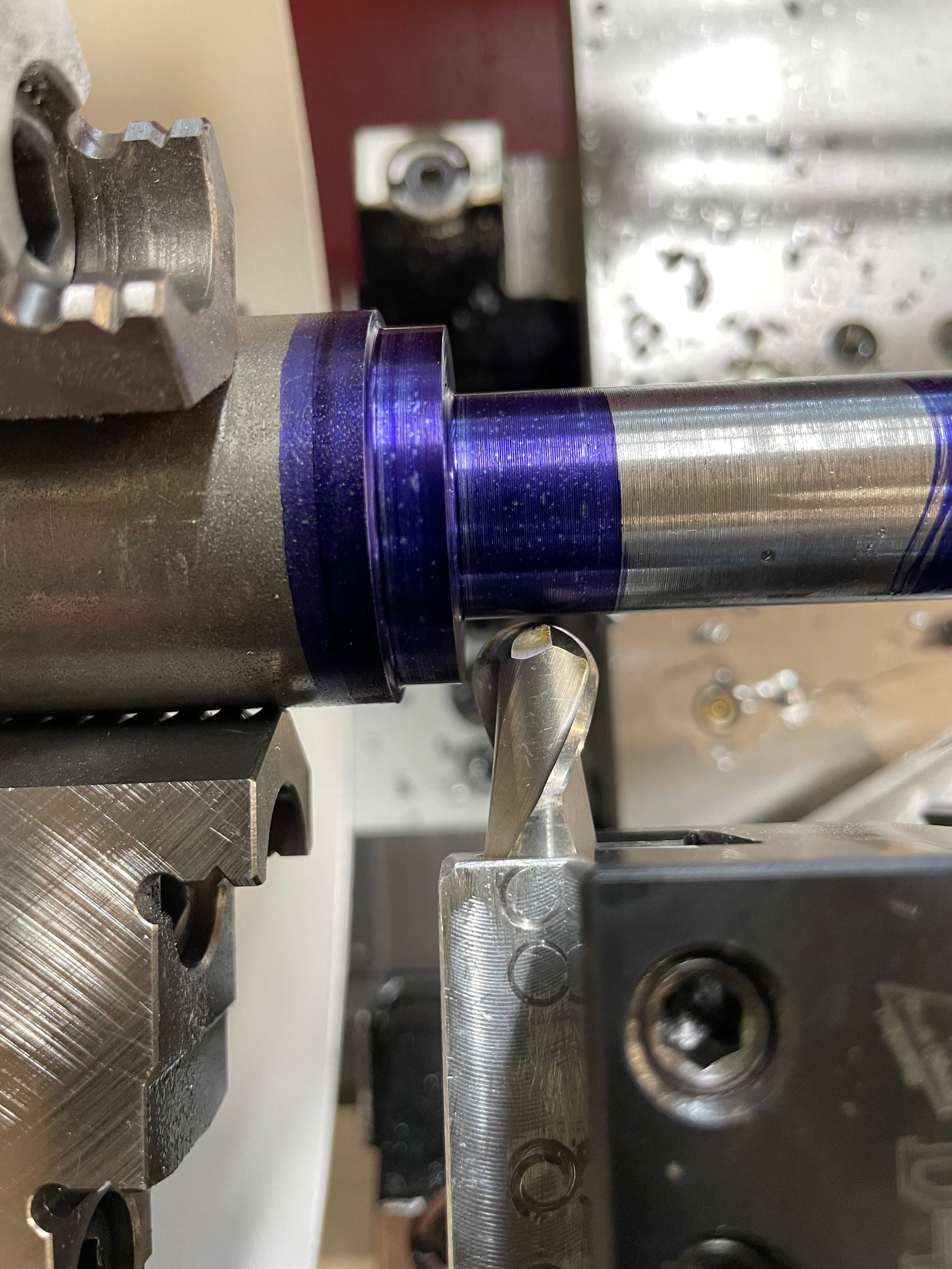
- Bring the center of the radius tool up to the corner of the part.
- Apply cutting oil.
- Gently work the tool in, a little on the cross-slide, then a little on the carriage. Back and forth with each until reaching the zero point on both hand wheels.
- Back the tool off and measure with a radius gage.
Step 1-4: Examine the print for the radius size. Calculate the step size that will be left in place of the radius. For instance, a 1/2″ radius would require a step of 1/2″ shorter in length, and 1″ larger in diameter to allow for the creation of the radius. Essentially, instead of making one rectangular shaped cut, two will be made. Rough and finish the largest diameter and full- length step. Rough and finish the smallest diameter and shortest length step.”
Step 5: Select a 90 degree radius cutting tool, install it in a tool holder on the tool post, and square it to the machine.
Step 6: Apply layout dye to the outside diameter and the face that will have the 90 degree radius.

Step 6: Apply layout dye to the outside diameter and the face that will have the 90 degree radius.
Step 9: Touch the radius tool to the finished diameter of where the radius will end.

Step 10: Set the cross-slide handwheel to zero.
Step 12: Touch the radius tool to the finished shoulder of where the radius will end.

Step 13: Set the carriage handwheel to zero.
Step 16: Apply cutting oil.

Step 17: Gently work the tool in, a little on the cross slide, then a little on the carriage. Back and forth with each until reaching the zero point on both hand wheels.

Step 17: Gently work the tool in, a little on the cross slide, then a little on the carriage. Back and forth with each until reaching the zero point on both hand wheels.
Step 18: Back the tool off and measure with a radius gage.
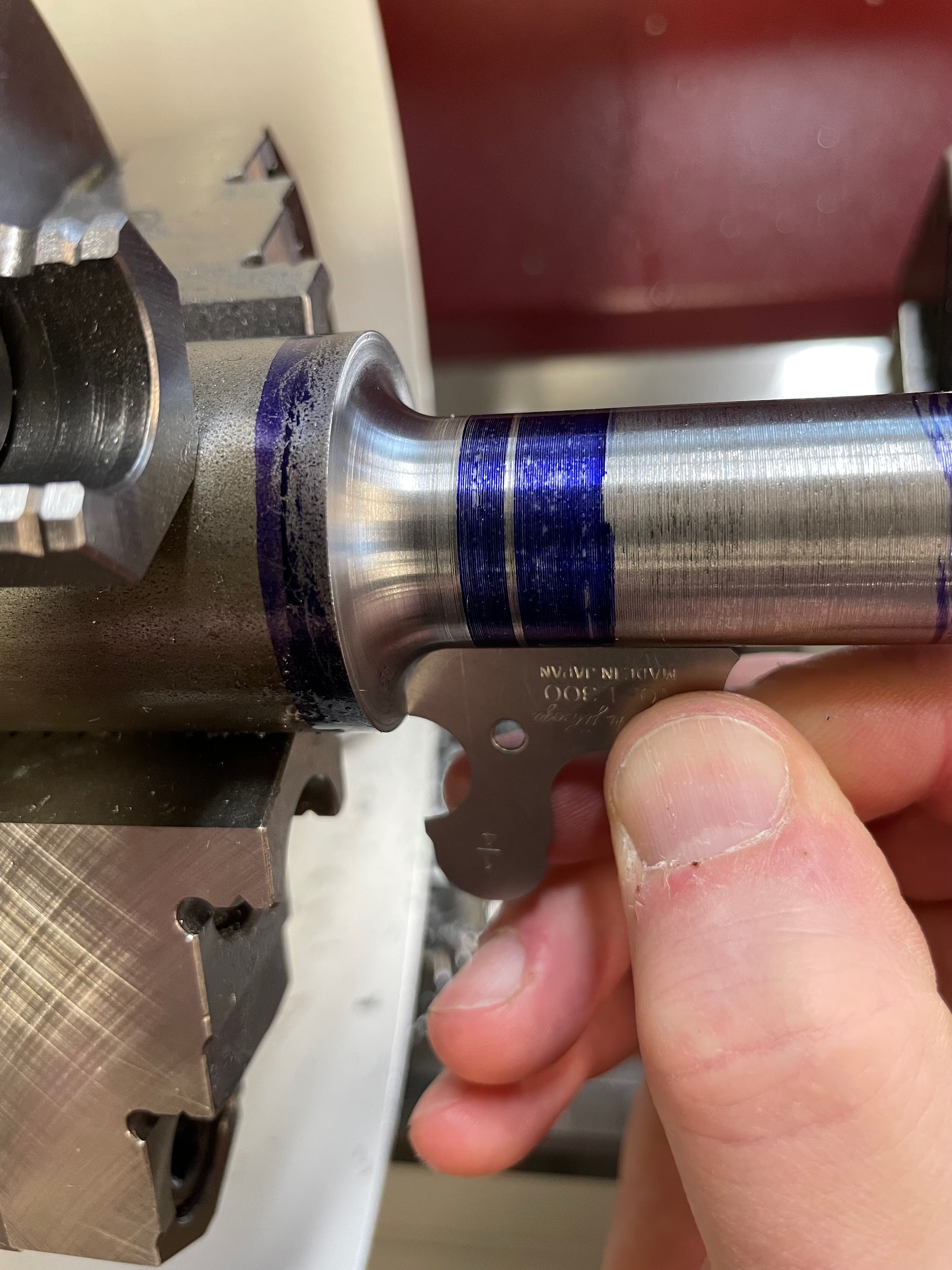
Figure 10.147. A hand holds a ¼” radius gauge, measuring the concave radius on the part. / Image Credit: Micky R. Jennings, courtesy of Wenatchee Valley College, CC BY 4.0
Author’s Tip
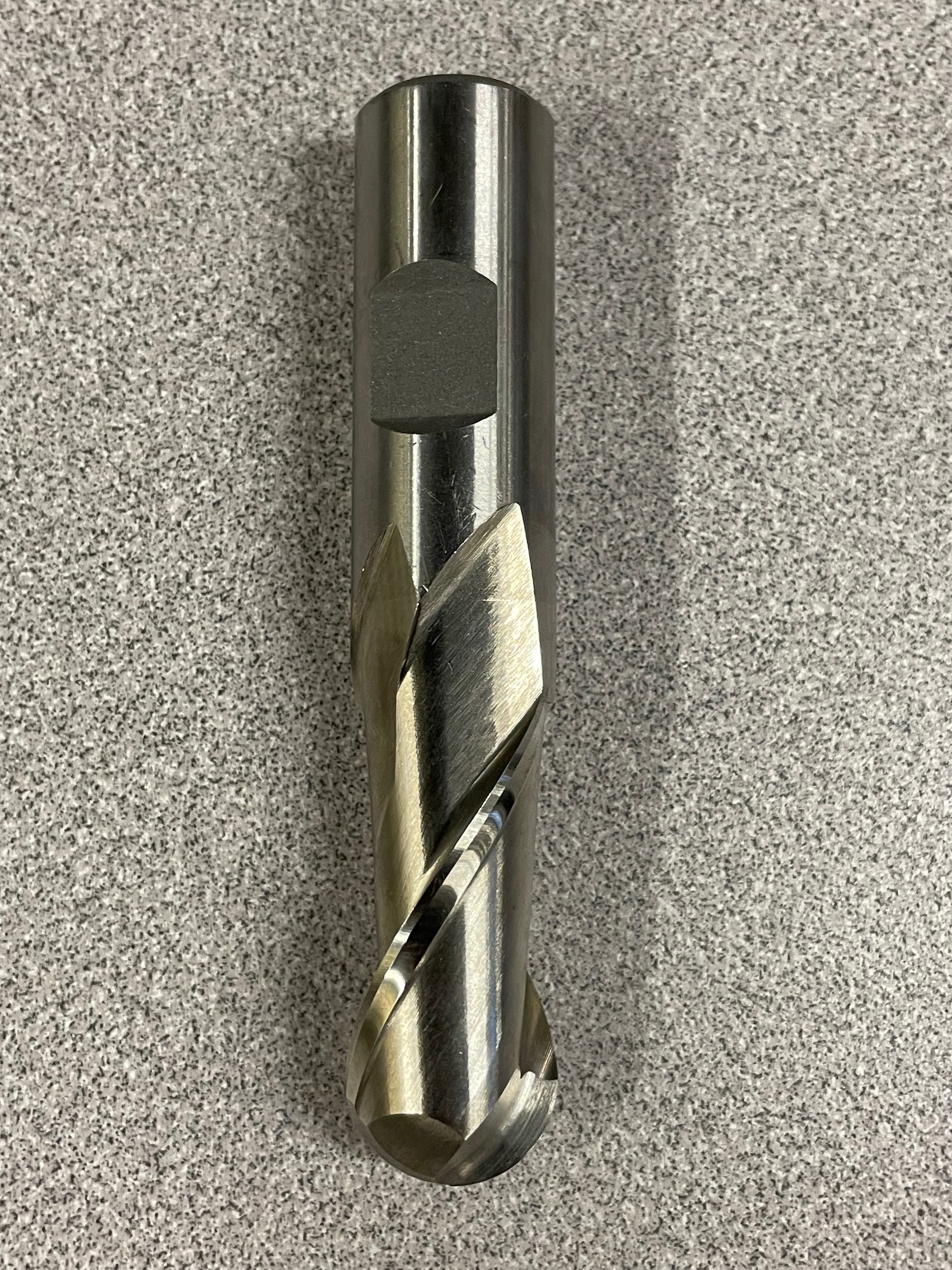
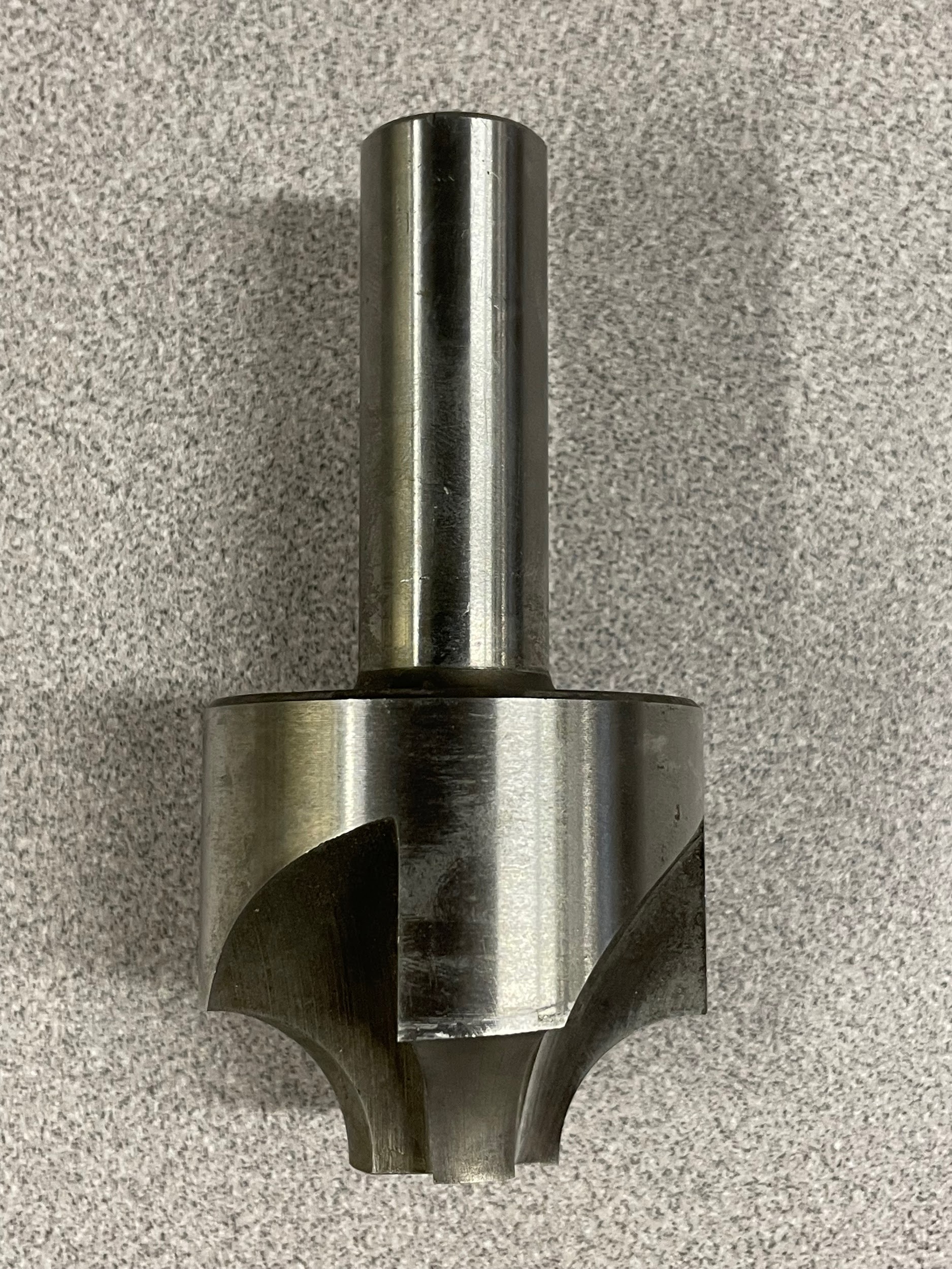
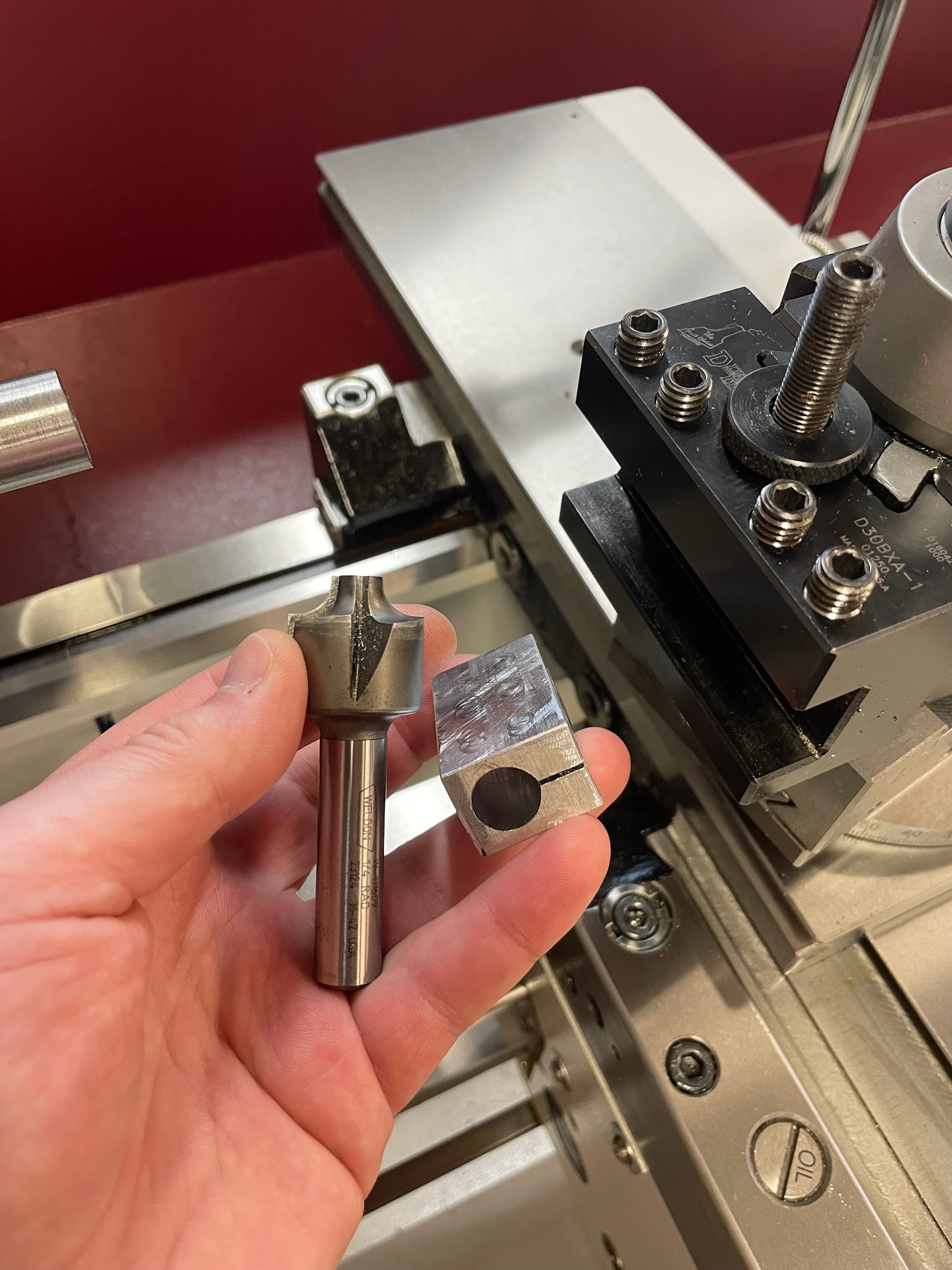
Professionally ground radius cutting tools are expensive, and it is difficult for us to create accurate circular shapes by off-hand grinding. For that reason, when I have a few parts to make and I don’t have the time or budget to access the nicer tools I would like, I turn to other tools in the shop. Ball end mills and milling radius cutters work beautifully as a precision solution to this issue. All you have to do is create a small rectangular block with a hole in it the size of the milling tool shank. Then cut a slit along one side so the block can be compressed by the set screws of the lathe tool holder and transmit the force onto the shank of the milling tool. Securely holding it in place. Turn impromptu precision radii with confidence!
Attributions
- Figure 10.129: Convex radius measurement by Micky R. Jennings, courtesy of Wenatchee Valley College, for WA Open ProfTech, © SBCTC, CC BY 4.0
- Figure 10.130: Ball end mill by Micky R. Jennings, courtesy of Wenatchee Valley College, for WA Open ProfTech, © SBCTC, CC BY 4.0
- Figure 10.131: Corner rounding tool by Micky R. Jennings, courtesy of Wenatchee Valley College, for WA Open ProfTech, © SBCTC, CC BY 4.0
- Figure 10.132: Tooling for radius cutting by Micky R. Jennings, courtesy of Wenatchee Valley College, for WA Open ProfTech, © SBCTC, CC BY 4.0
- Figure 10.133: Convex tool by Micky R. Jennings, courtesy of Wenatchee Valley College, for WA Open ProfTech, © SBCTC, CC BY 4.0
- Figure 10.134: Convex radius tool height by Micky R. Jennings, courtesy of Wenatchee Valley College, for WA Open ProfTech, © SBCTC, CC BY 4.0
- Figure 10.135: Convex radius tool height by Micky R. Jennings, courtesy of Wenatchee Valley College, for WA Open ProfTech, © SBCTC, CC BY 4.0
- Video 10.67: Micky R. Jennings, courtesy of Wenatchee Valley College, for WA Open ProfTech, © SBCTC, CC BY 4.0
- Video 10.68: Micky R. Jennings, courtesy of Wenatchee Valley College, for WA Open ProfTech, © SBCTC, CC BY 4.0
- Figure 10.136: Zeroing the carriage handwheel by Micky R. Jennings, courtesy of Wenatchee Valley College, for WA Open ProfTech, © SBCTC, CC BY 4.0
- Video 10.69: Micky R. Jennings, courtesy of Wenatchee Valley College, for WA Open ProfTech, © SBCTC, CC BY 4.0
- Figure 10.137: Zeroing the cross slide handwheel by Micky R. Jennings, courtesy of Wenatchee Valley College, for WA Open ProfTech, © SBCTC, CC BY 4.0
- Video 10.70: Micky R. Jennings, courtesy of Wenatchee Valley College, for WA Open ProfTech, © SBCTC, CC BY 4.0
- Video 10.71: Micky R. Jennings, courtesy of Wenatchee Valley College, for WA Open ProfTech, © SBCTC, CC BY 4.0
- Figure 10.138: Finished convex radius by Micky R. Jennings, courtesy of Wenatchee Valley College, for WA Open ProfTech, © SBCTC, CC BY 4.0
- Figure 10.139: Finished convex radius 2 by Micky R. Jennings, courtesy of Wenatchee Valley College, for WA Open ProfTech, © SBCTC, CC BY 4.0
- Figure 10.140: Convex radius measurement by Micky R. Jennings, courtesy of Wenatchee Valley College, for WA Open ProfTech, © SBCTC, CC BY 4.0
- Figure 10.141: Prep for concave radius by Micky R. Jennings, courtesy of Wenatchee Valley College, for WA Open ProfTech, © SBCTC, CC BY 4.0
- Figure 10.142: Concave radius tool by Micky R. Jennings, courtesy of Wenatchee Valley College, for WA Open ProfTech, © SBCTC, CC BY 4.0
- Video 10.72: Micky R. Jennings, courtesy of Wenatchee Valley College, for WA Open ProfTech, © SBCTC, CC BY 4.0
- Figure 10.143: Positioning concave radius tool by Micky R. Jennings, courtesy of Wenatchee Valley College, for WA Open ProfTech, © SBCTC, CC BY 4.0
- Video 10.73: Micky R. Jennings, courtesy of Wenatchee Valley College, for WA Open ProfTech, © SBCTC, CC BY 4.0
- Figure 10.144: Zeroing the cross slide handwheel by Micky R. Jennings, courtesy of Wenatchee Valley College, for WA Open ProfTech, © SBCTC, CC BY 4.0
- Video 10.74: Micky R. Jennings, courtesy of Wenatchee Valley College, for WA Open ProfTech, © SBCTC, CC BY 4.0
- Figure 10.145: Zeroing the carriage handwheel by Micky R. Jennings, courtesy of Wenatchee Valley College, for WA Open ProfTech, © SBCTC, CC BY 4.0
- Video 10.75: Micky R. Jennings, courtesy of Wenatchee Valley College, for WA Open ProfTech, © SBCTC, CC BY 4.0
- Video 10.76: Micky R. Jennings, courtesy of Wenatchee Valley College, for WA Open ProfTech, © SBCTC, CC BY 4.0
- Figure 10.146: Finished concave radius by Micky R. Jennings, courtesy of Wenatchee Valley College, for WA Open ProfTech, © SBCTC, CC BY 4.0
- Figure 10.147: Concave radius measurement by Micky R. Jennings, courtesy of Wenatchee Valley College, for WA Open ProfTech, © SBCTC, CC BY 4.0
