10.17 Threading
Micky R. Jennings
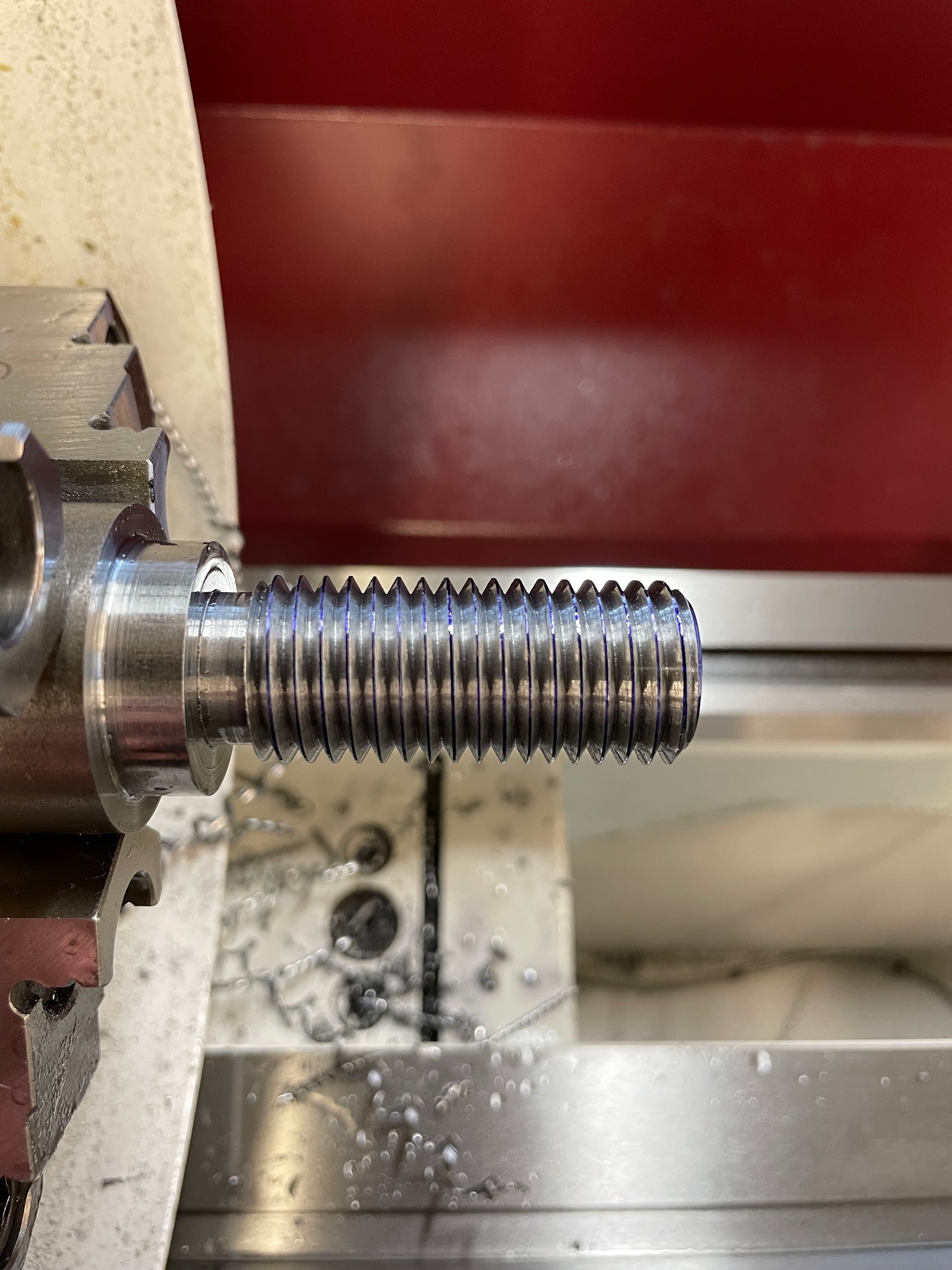
Threading is the process of creating a precision angular helical groove down the length of a shaft. The result of this cutting operation is known as a thread. There are many types of threads that could be discussed, but the most common are unified inch threads and metric threads. This text will discuss the basics of single point cutting unified threads. This process can easily be adapted for cutting metric threads. Before beginning to cut threads, it is important to define some thread terminology.
Terminology
Nominal Diameter
The nominal diameter of the thread is a general reference term. For example, you might hear a machinist mention a 1/2″ bolt. The nominal diameter is 1/2″, but that isn’t what the outside of the thread really measures.
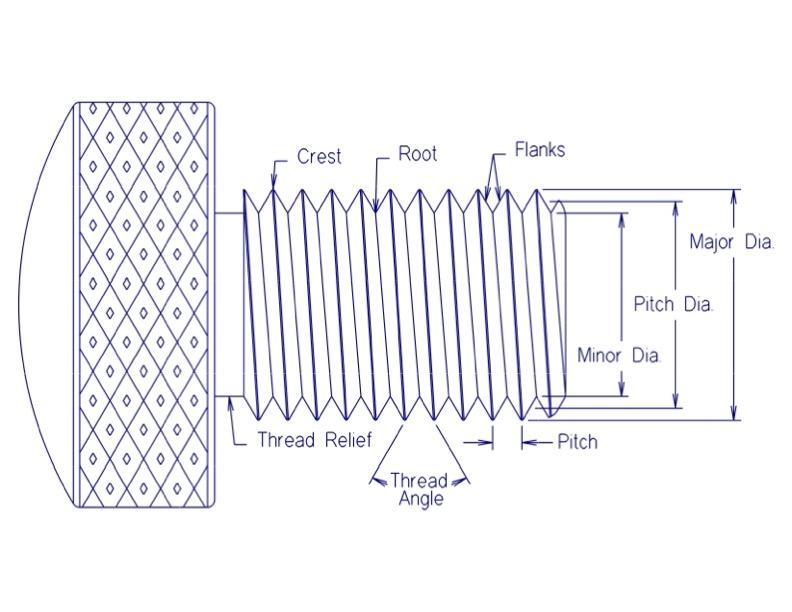
Major Diameter
The major diameter of an external thread is what the outside diameter of the thread actually measures, generally slightly smaller than nominal. For internal threads, the major diameter is the largest diameter of the thread being cut.
Minor Diameter
The minor diameter of an external thread refers to the smallest diameter of the thread being cut. For internal threads, the minor diameter is the same as the tap drill size when looking to maintain 75% thread engagement.
Pitch Diameter
The pitch diameter is the imaginary diameter that exists at the point where 1/2 of the thread’s pitch would lie horizontally on a single thread. This is one of the most important parts of a thread to measure because it is where internal and external threads meet.
Threads Per Inch
Also known as TPI, threads per inch is used in describing inch thread sizes. For example, a 1/2-13 thread has a nominal diameter of 1/2″ and a TPI of 13. Metric threads don’t use TPI to describe threads; they just use the thread pitch.
Pitch
The pitch of a thread is the distance from one point on a thread to the same point on another thread. Knowing the size of a thread, the pitch can be calculated with the formula:
Pitch = 1/TPI
For example, a 1/2-13 thread has a pitch of .077 because 1/13 = .077
Lead
The lead of a thread is the distance a threaded shaft would travel inside a nut when turned one full rotation. For a single start thread, the lead is equal to the thread pitch. For a double start thread, the lead would be twice the thread pitch, and so on.
Crest
The crest of a thread is the small flat at the major diameter of an external thread and the minor diameter of an internal thread.
Root
The root of a thread is the bottom surface generated by the thread cutting tool. On an external thread, the root would be at the minor diameter, and on an internal thread, the root would be at the major diameter.
Flank
The flank of the thread is the angular portion between the crest and root. The vee shape cut on the thread, from one flank to the other flank, measures 60 degrees on both inch and metric threads.
Step by step process for external threading:
- Turn the outside major diameter of the area to be threaded. The major diameter and tolerance for any thread can be looked up in a manufacturing reference book.
- Chamfer the face end of the shaft to be threaded. The size of this chamfer should be about down to the minor diameter.
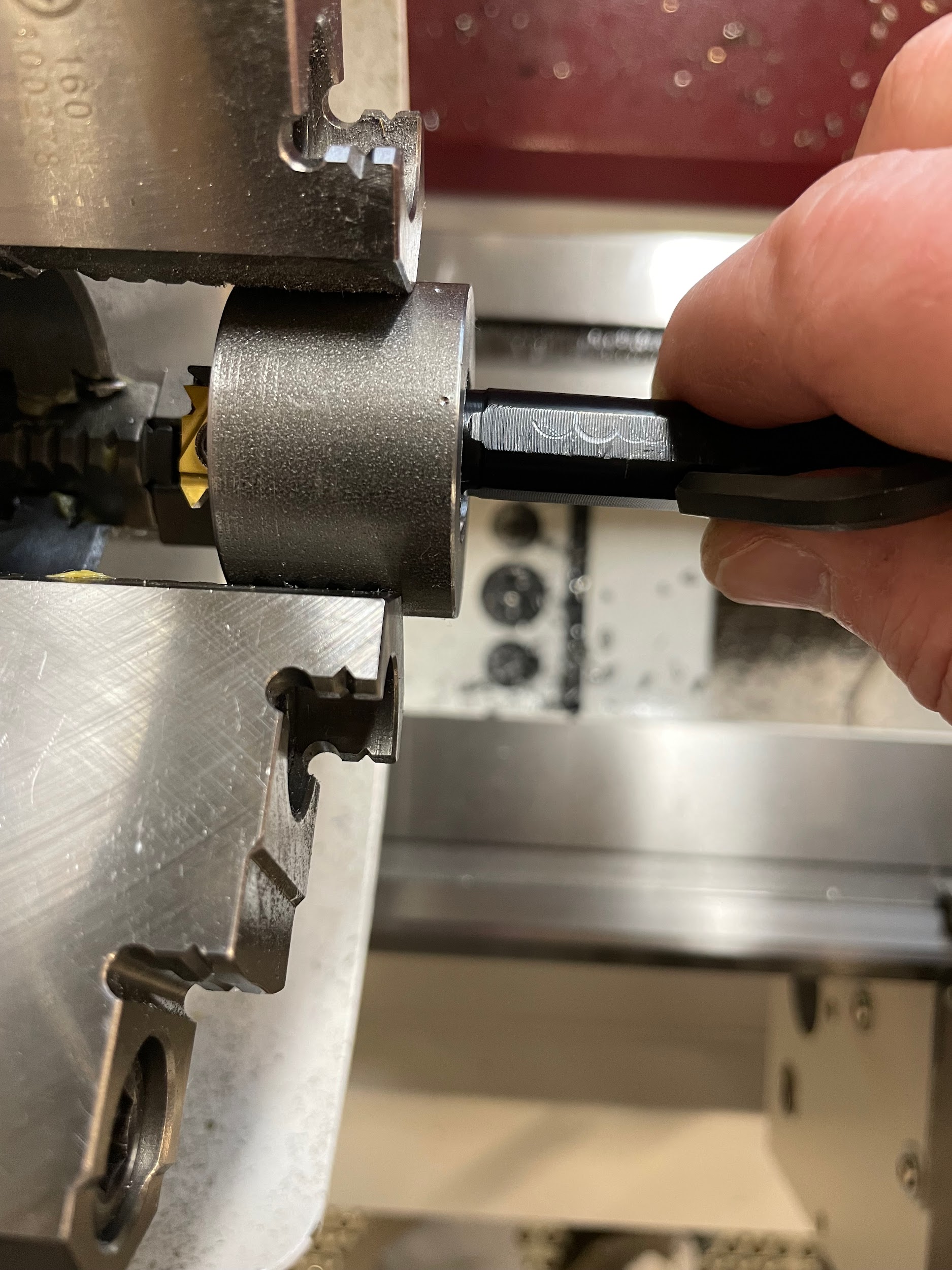
- Load a 60 degree threading tool into a tool holder and onto the tool post of the lathe and set the height.
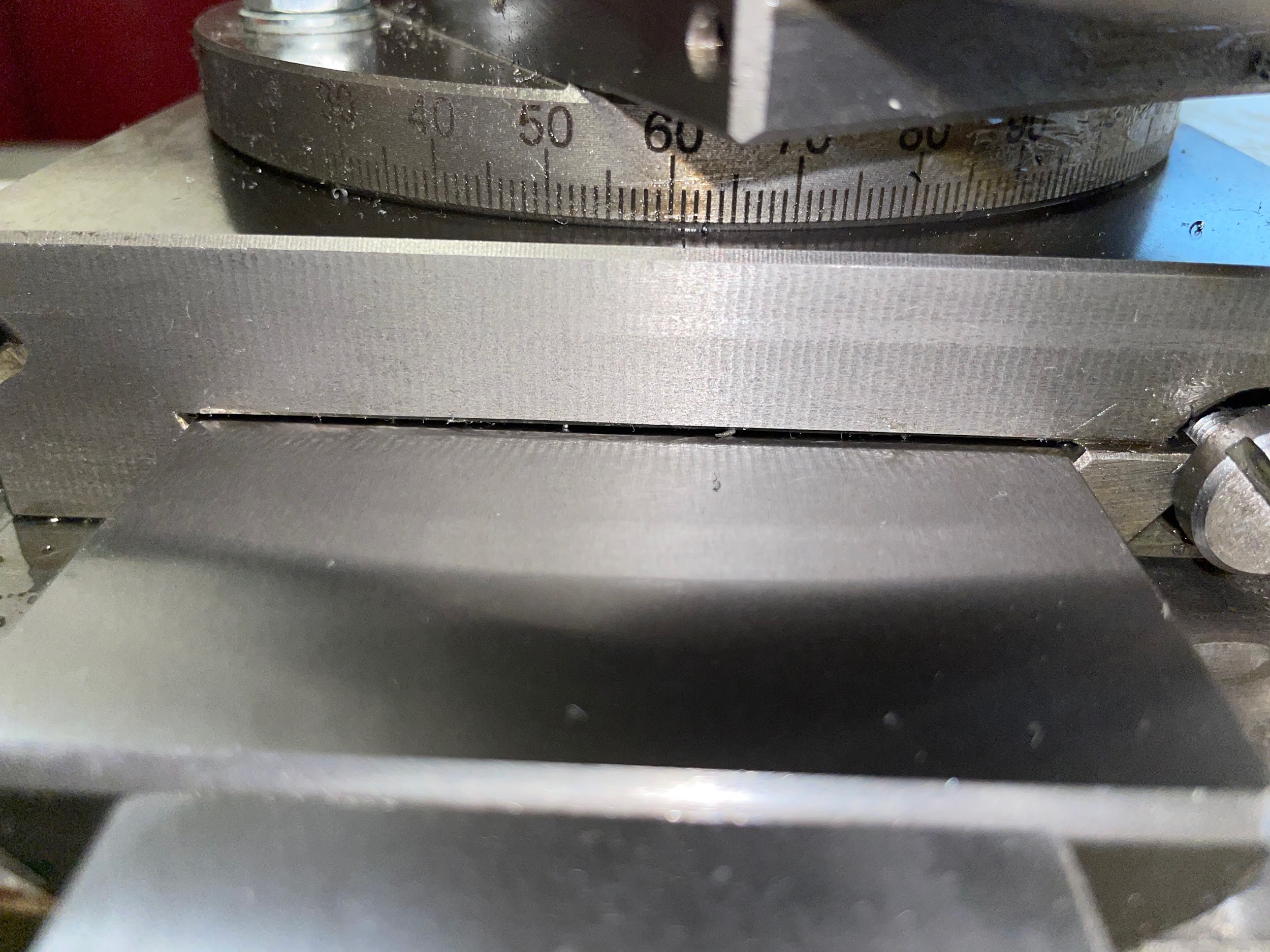
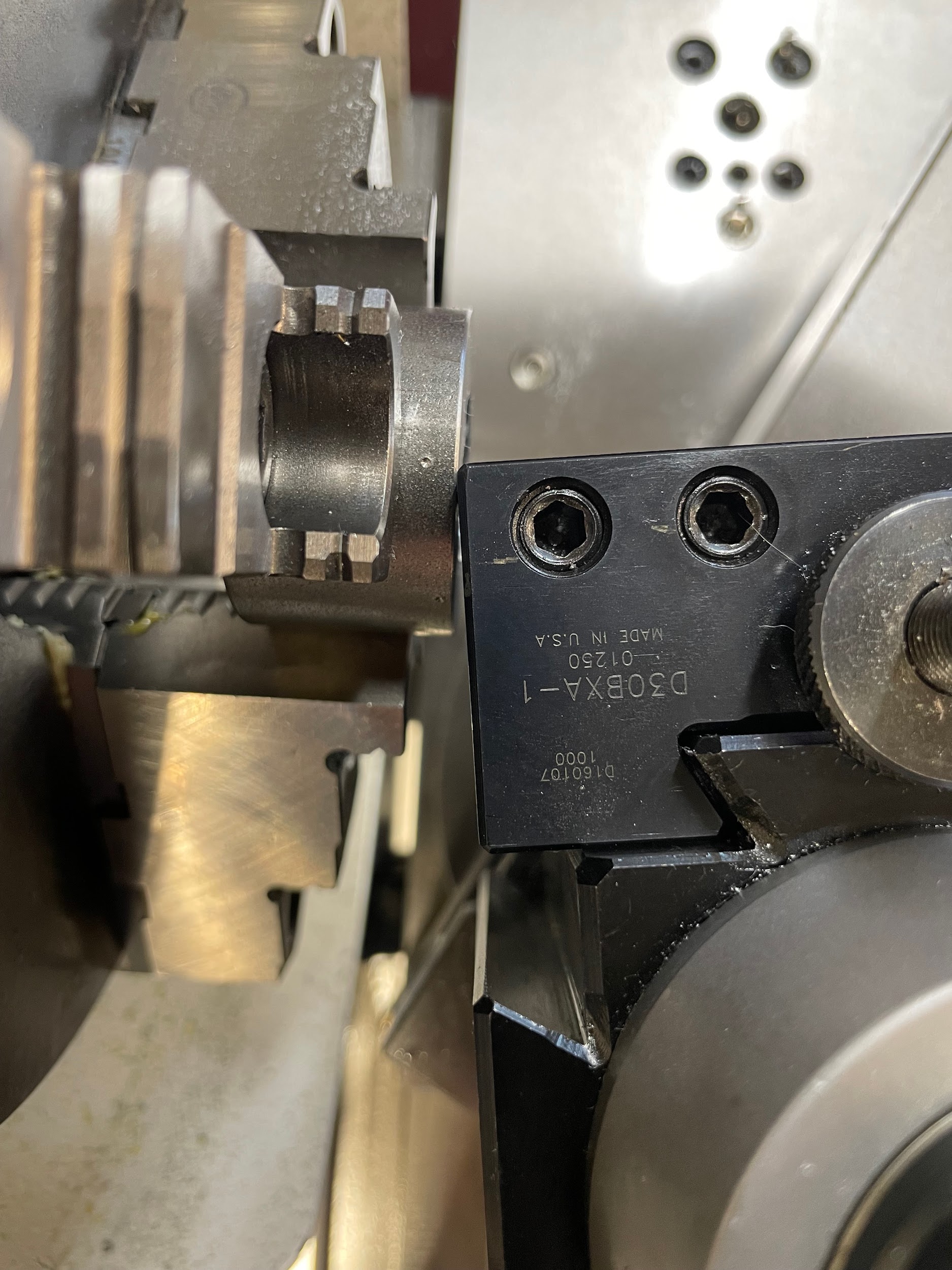
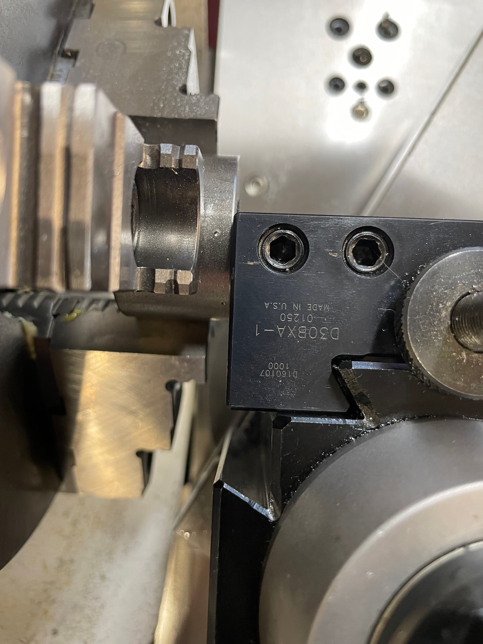
- Adjust the angle of the compound rest so that it is pointing 29 degrees from being perpendicular to the work. It is important to note that the compound rest should not be set to 29 degrees. This is the angle at which the tool will be advancing for the depth of cut. The reason for the angle is so that the tool cuts a majority of the material from the leading edge of the tool and the chip has room to flow across the chip tool interface. If the depth of cut were to be made strictly perpendicular to the work, the chip would try to form equally from both sides of the cutting tool and bunch up near the fragile tip and potentially break it.
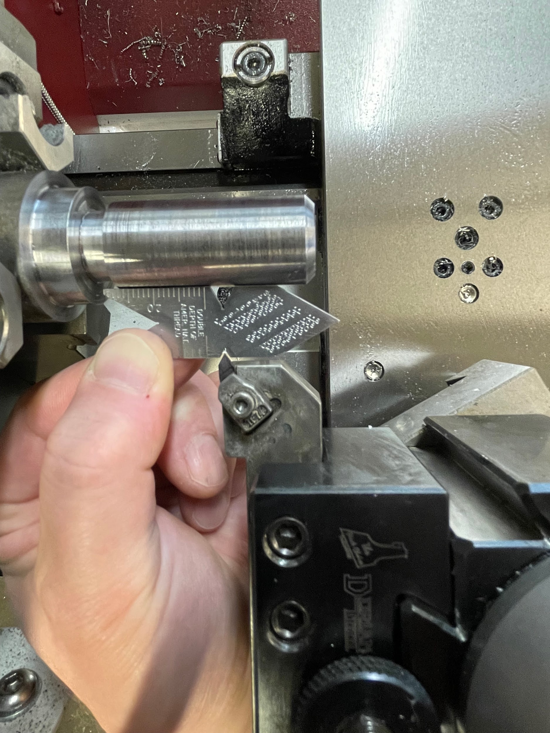
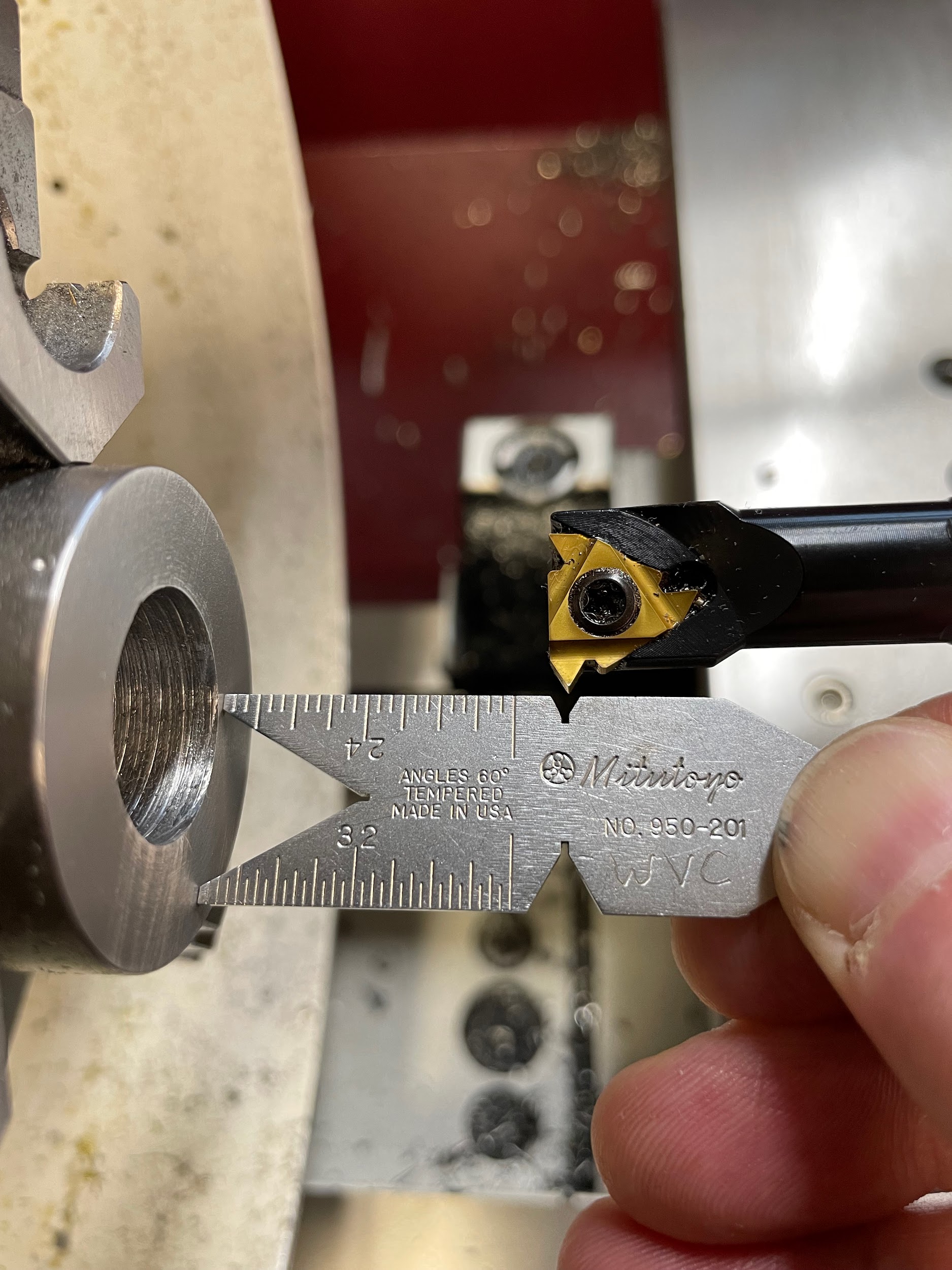
- Using a center gage, make sure the tool is pointed perpendicular to the work.
- Select a slow spindle speed for threading, generally about 100 RPMs for beginners. On a gear head lathe, once the threading process has been started, the spindle speed cannot be altered without ruining the alignment of the thread.
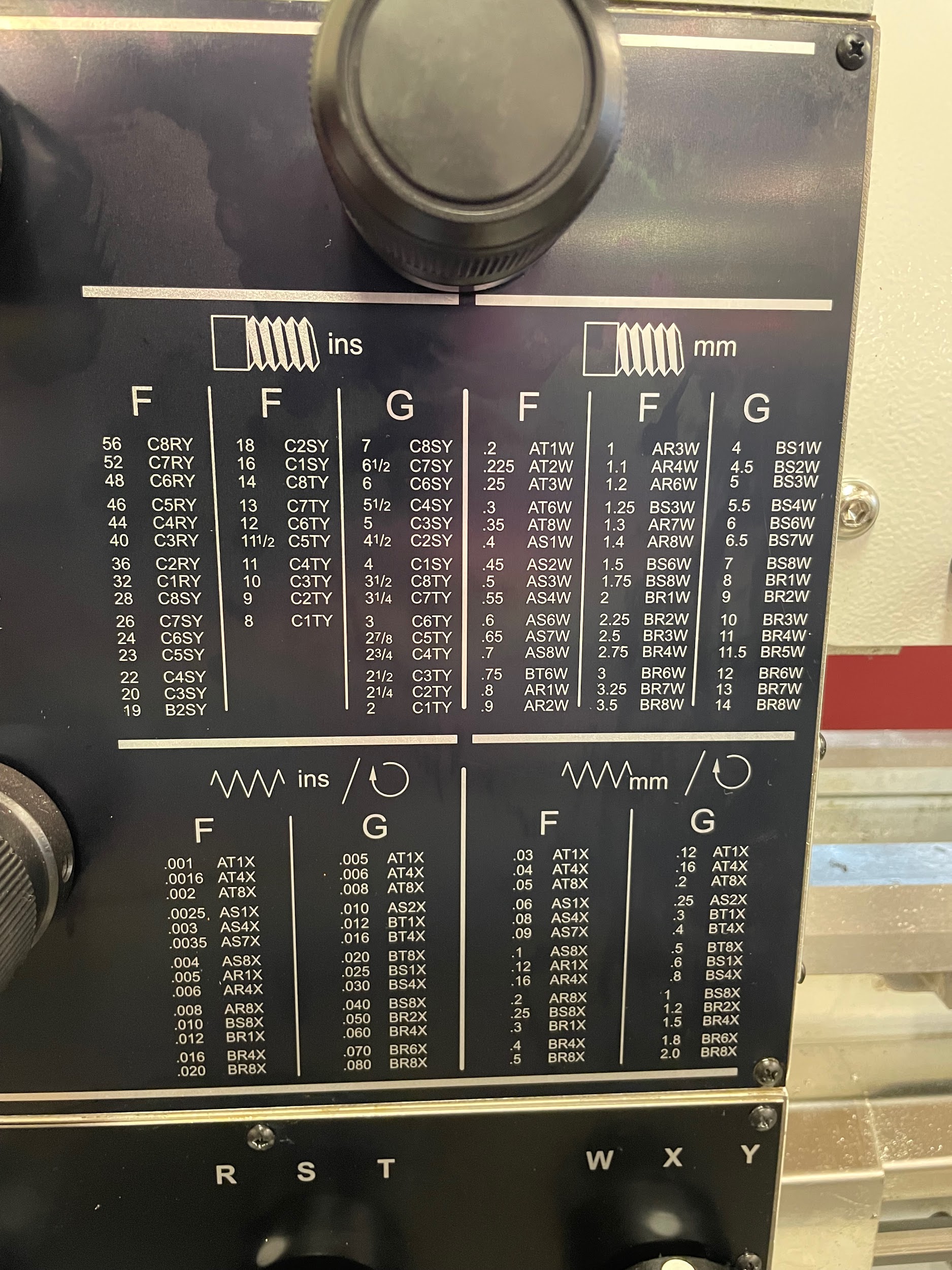
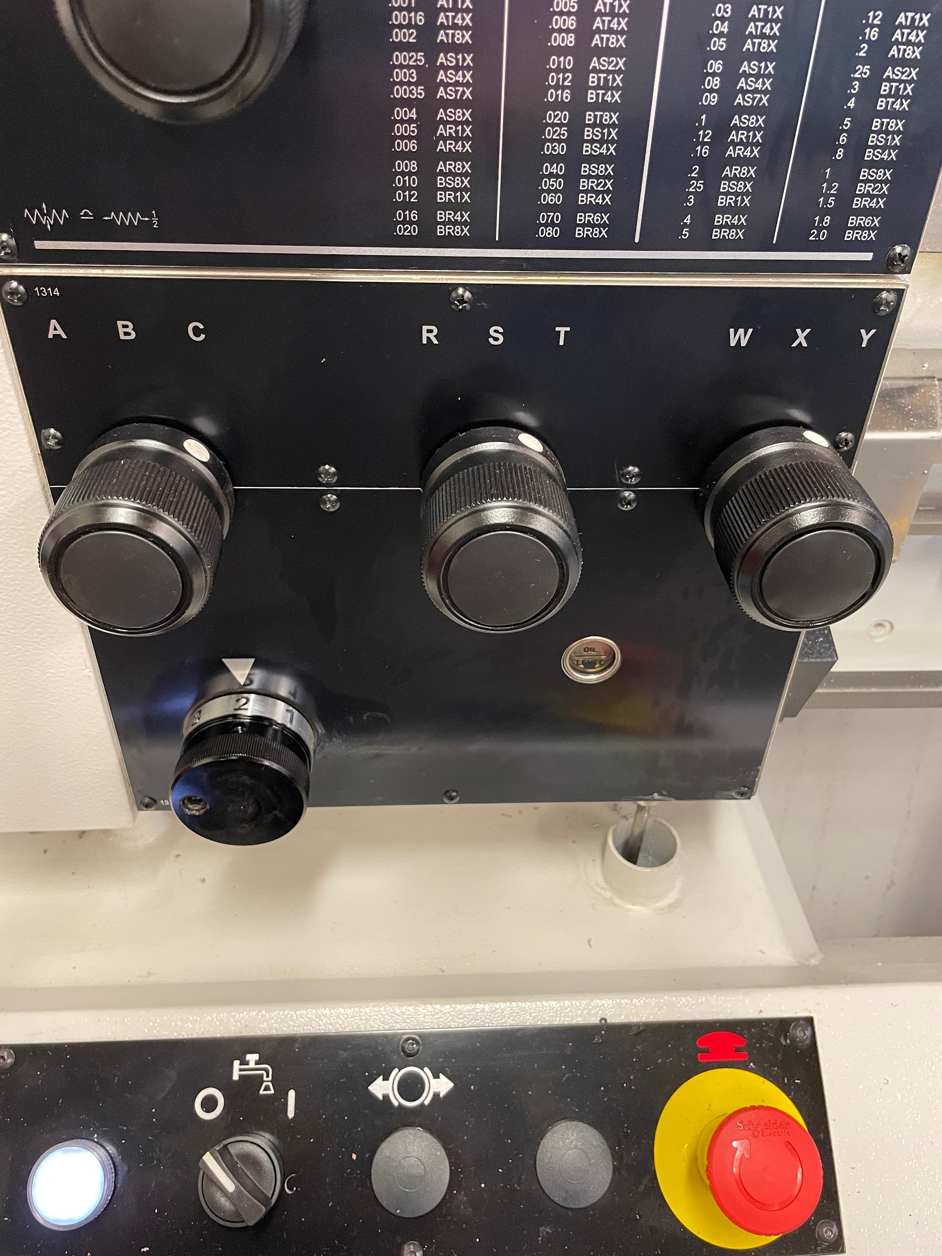
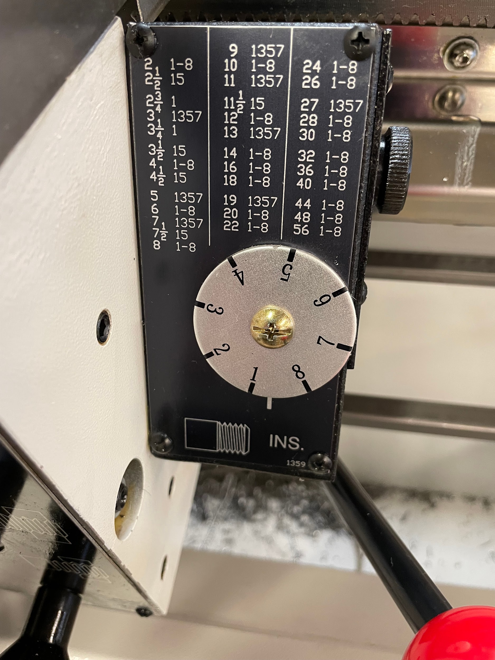
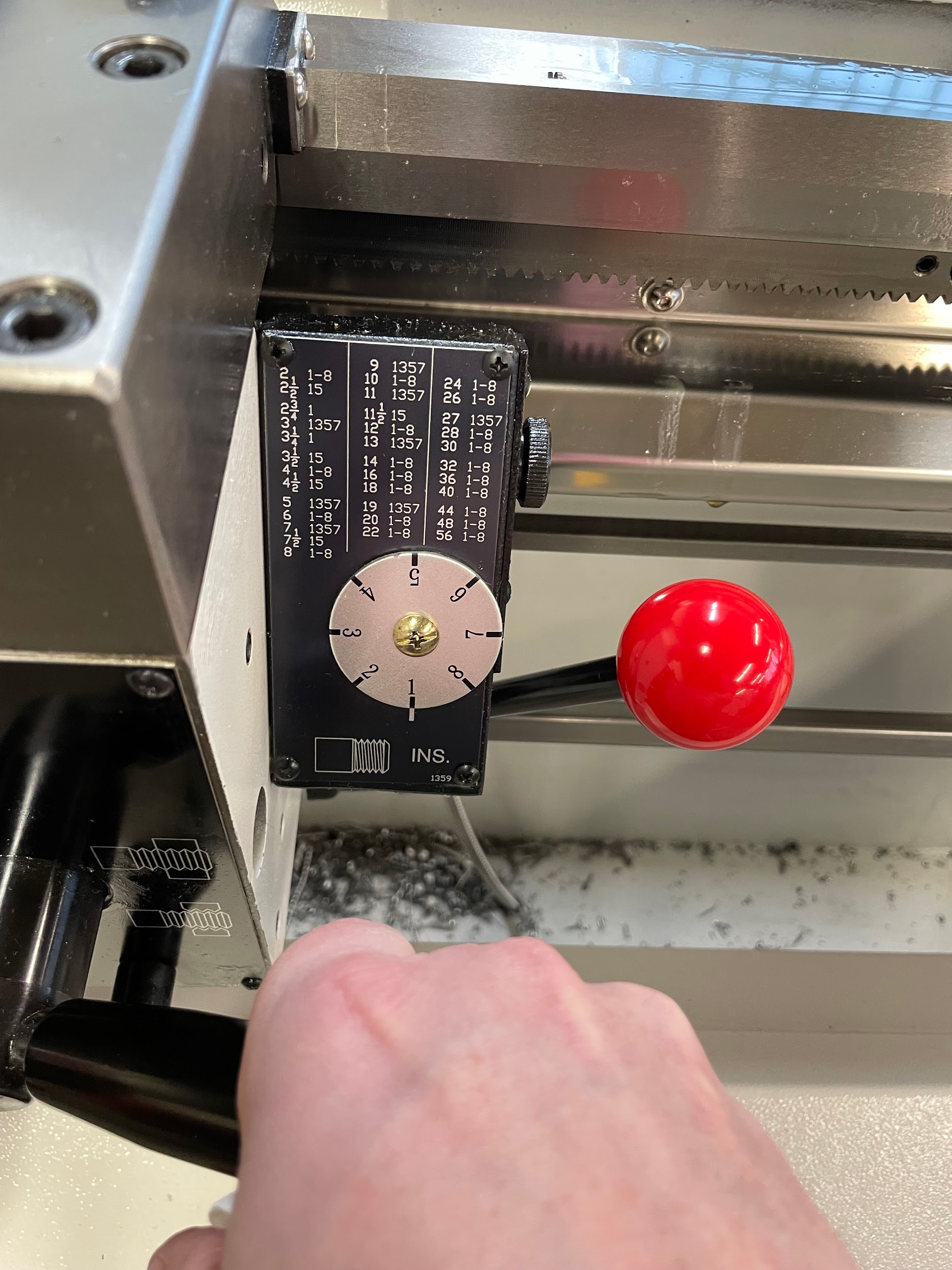
- Using the quick change gear box, select the TPI required.
- Turn the spindle on and make sure the machine is in gear and that the lead screw is turning.
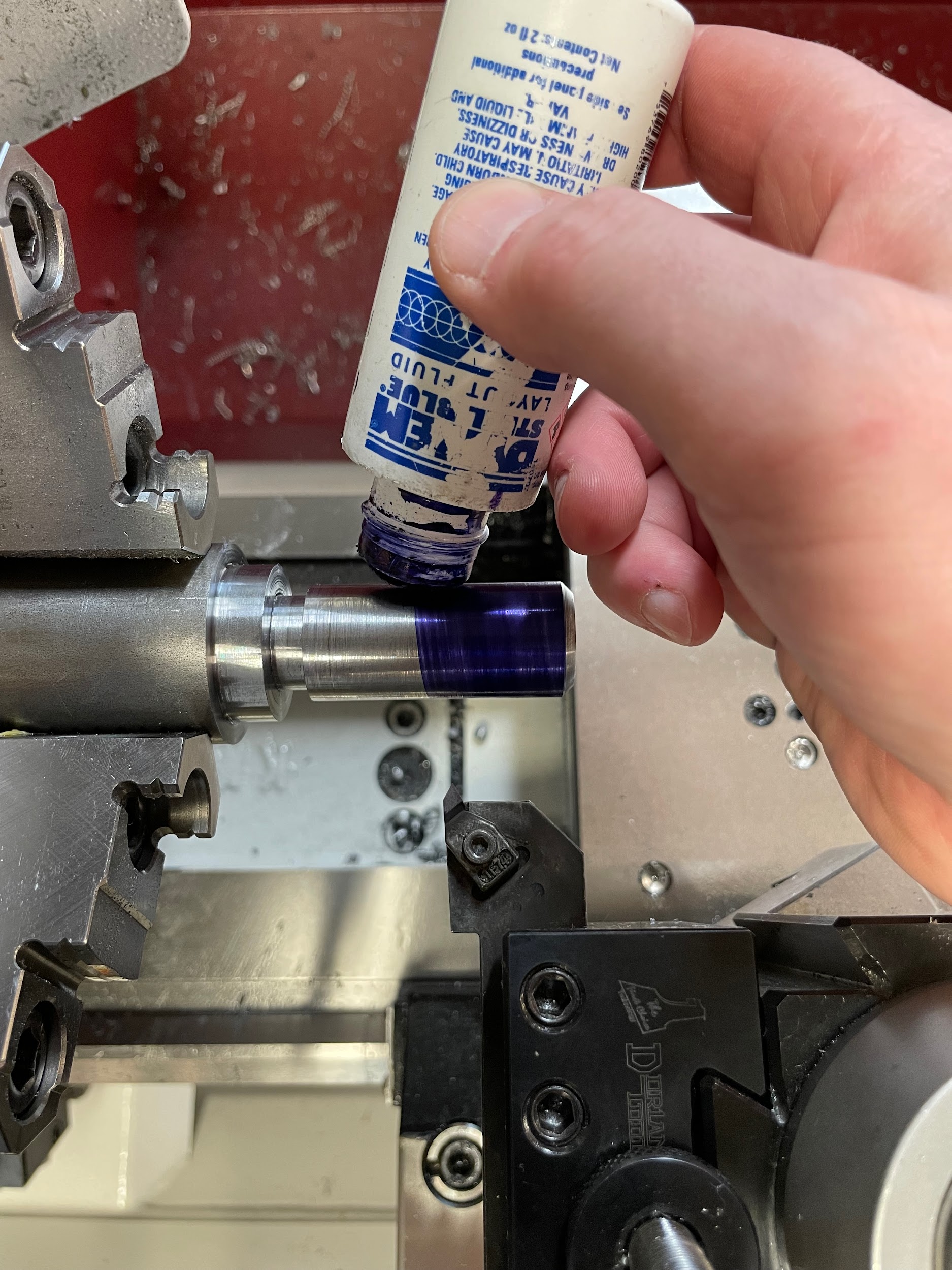
- Apply layout dye to the outside of the portion to be threaded.
- Scribe a line with odd leg calipers at the point where the thread will end.
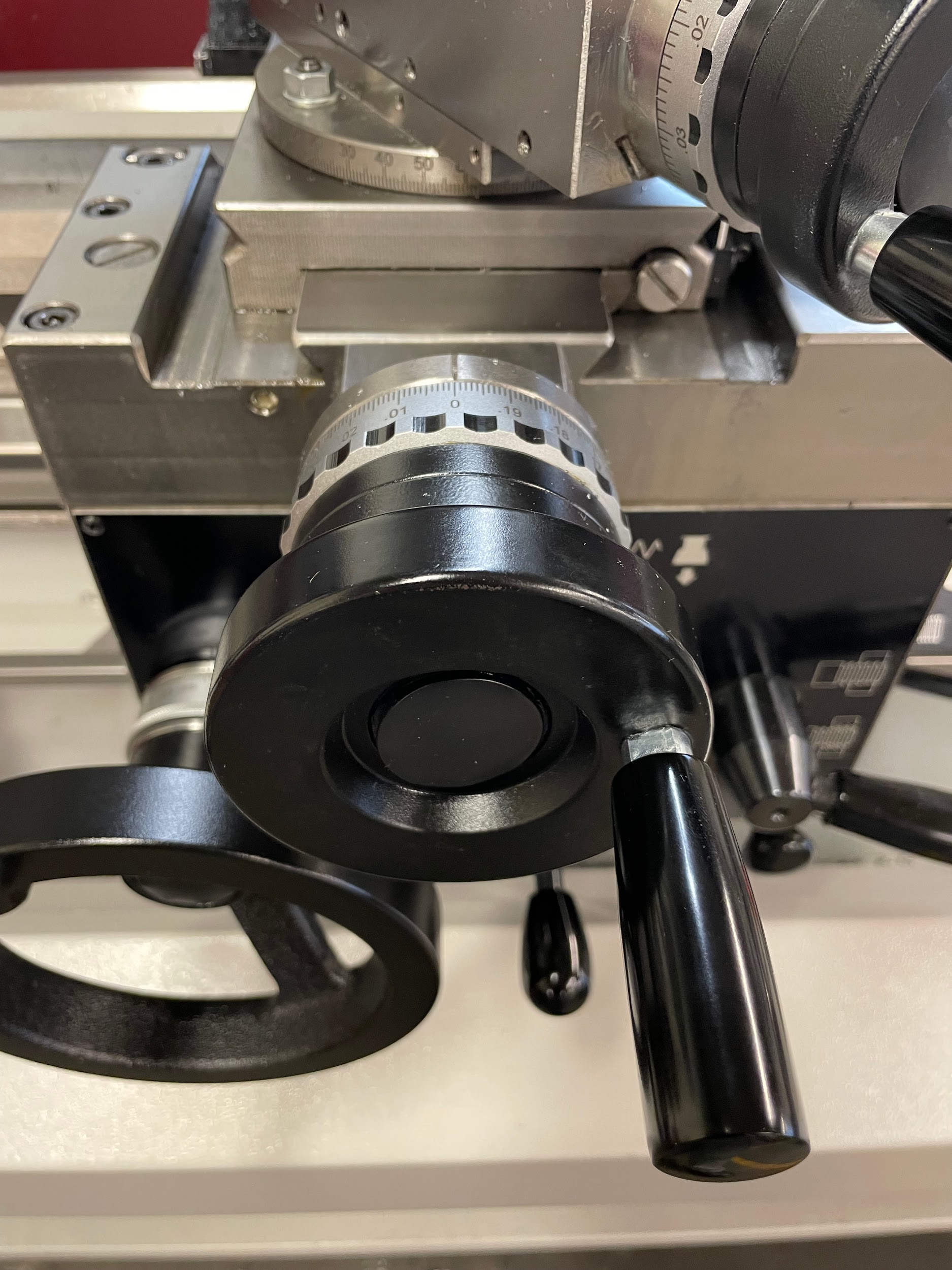
- Move the cross slide so that the tool is as close as it will get to the work with the handle of the hand wheel in the three o’clock position.
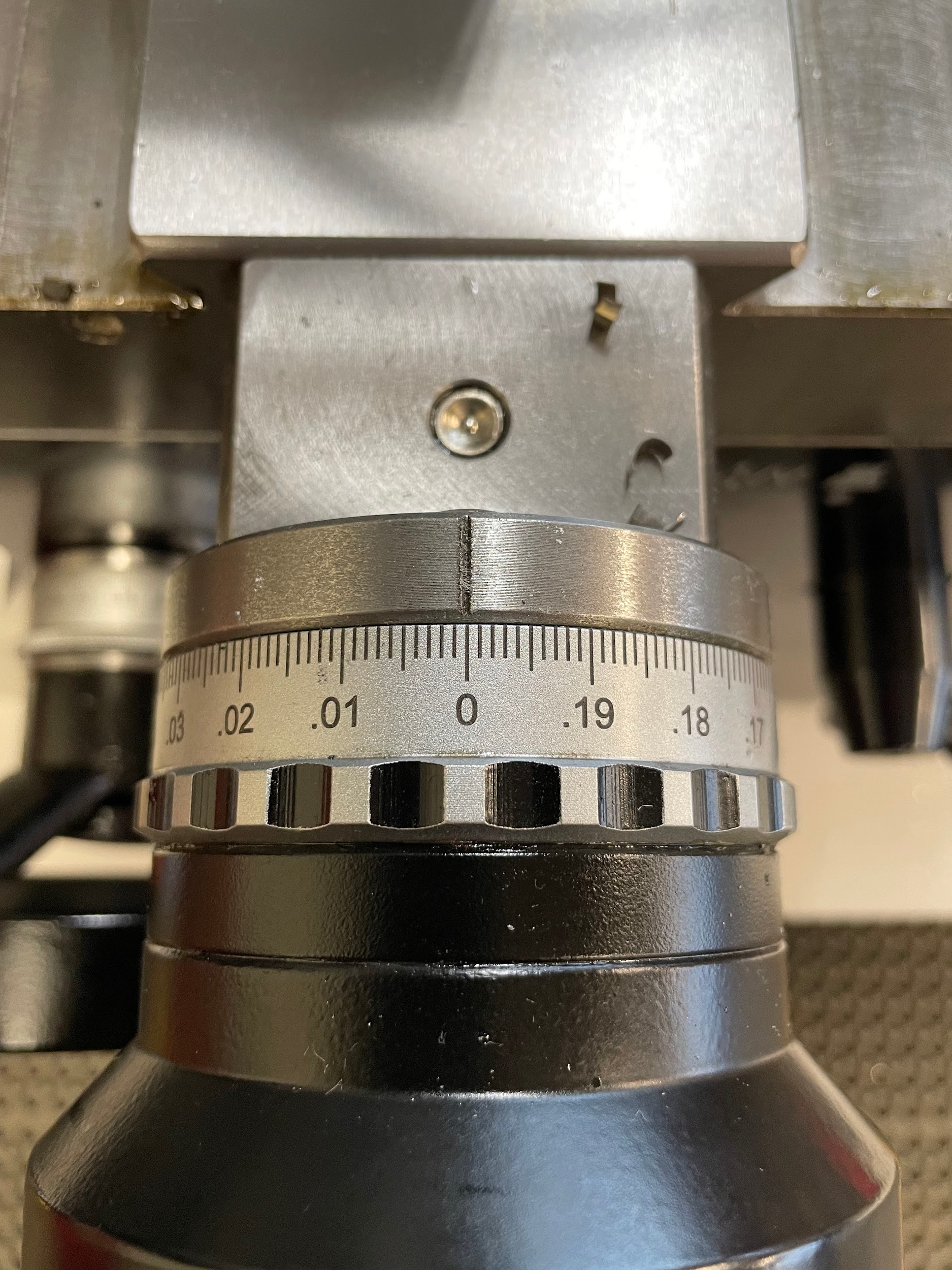
- Set the graduated collar on the cross slide to zero.
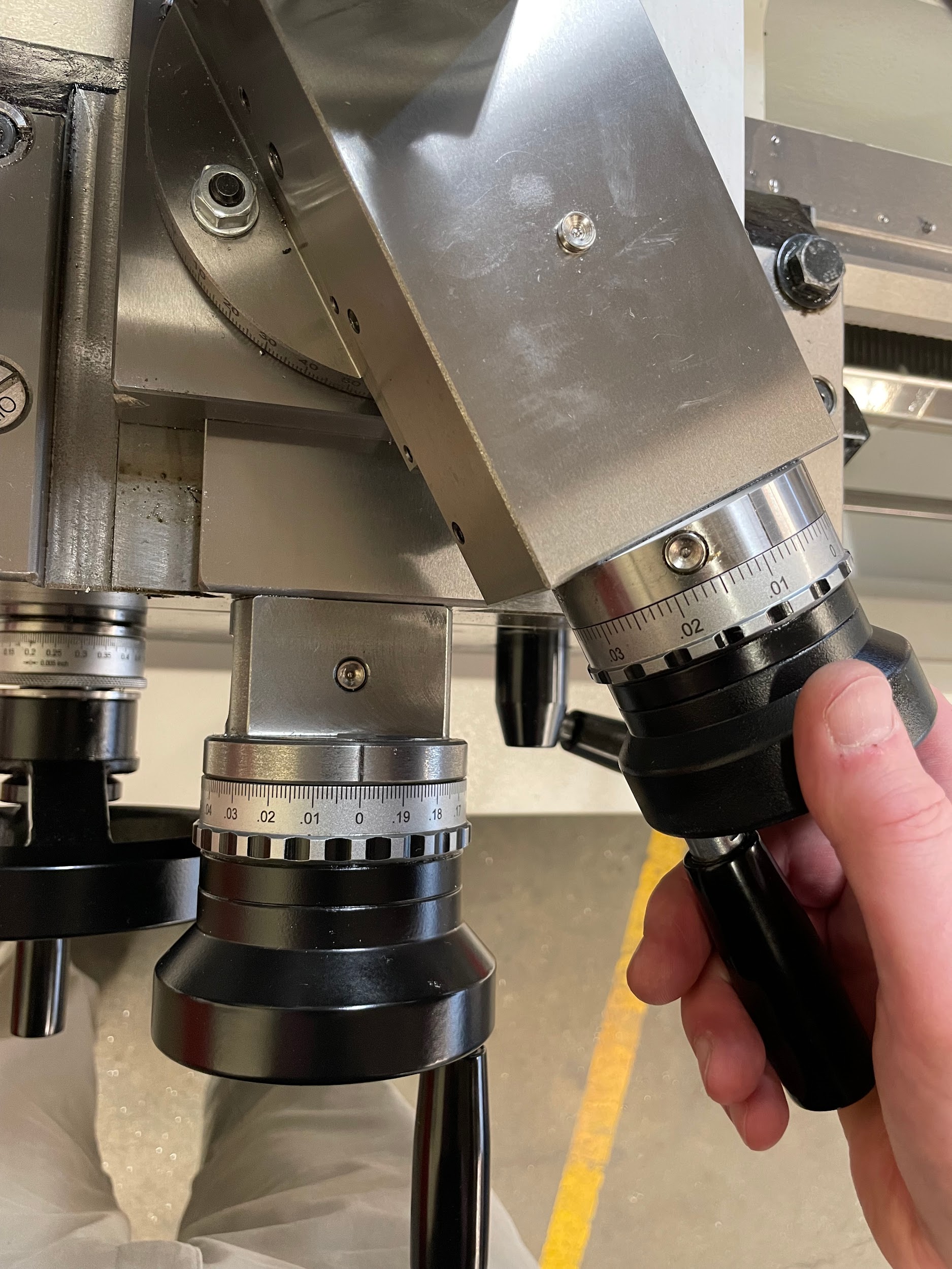
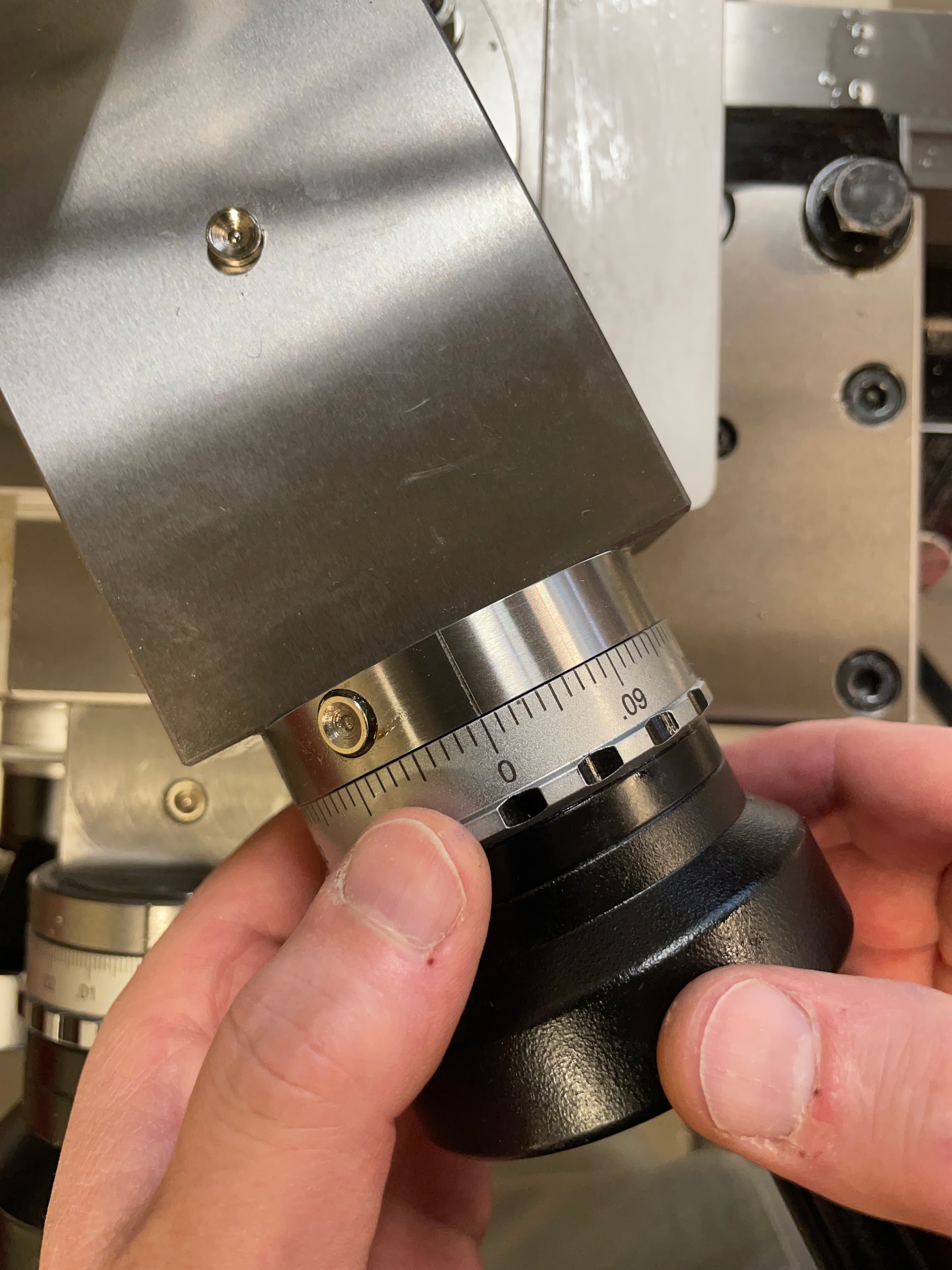
- Adjust the compound rest so that the tool just touches the outside of the work.
- Zero the graduated collar on the compound rest.
- Move the carriage to about 1/2″ in front of the part.
- Advance the compound rest a couple of thousandths to make a scratch pass for thread inspection.
- Select a timing mark or series of marks to engage the half nut lever.
- With a brush, spread cutting oil on the outside of the shaft.
- Place the left hand on the cross slide handle, being prepared to pull out of the thread.
- Engage the half nut and keep a hand on the lever. Make sure it is fully engaged and on the correct timing mark.
- Watch the tool cut along the outside of the shaft. Once the tool has reached the scribe mark, quickly pull out one full turn of the cross slide with the left hand and then disengage the half nut lever with the right hand. This motion needs to happen quickly and precisely in order to not overtravel the designated thread length or put grooves in the threaded section. Pulling out first is the safest option whenever needing to end the thread cutting operation.
- Move the carriage to the front of the thread again.
- Reset the cross slide to the zero and three o’clock position.
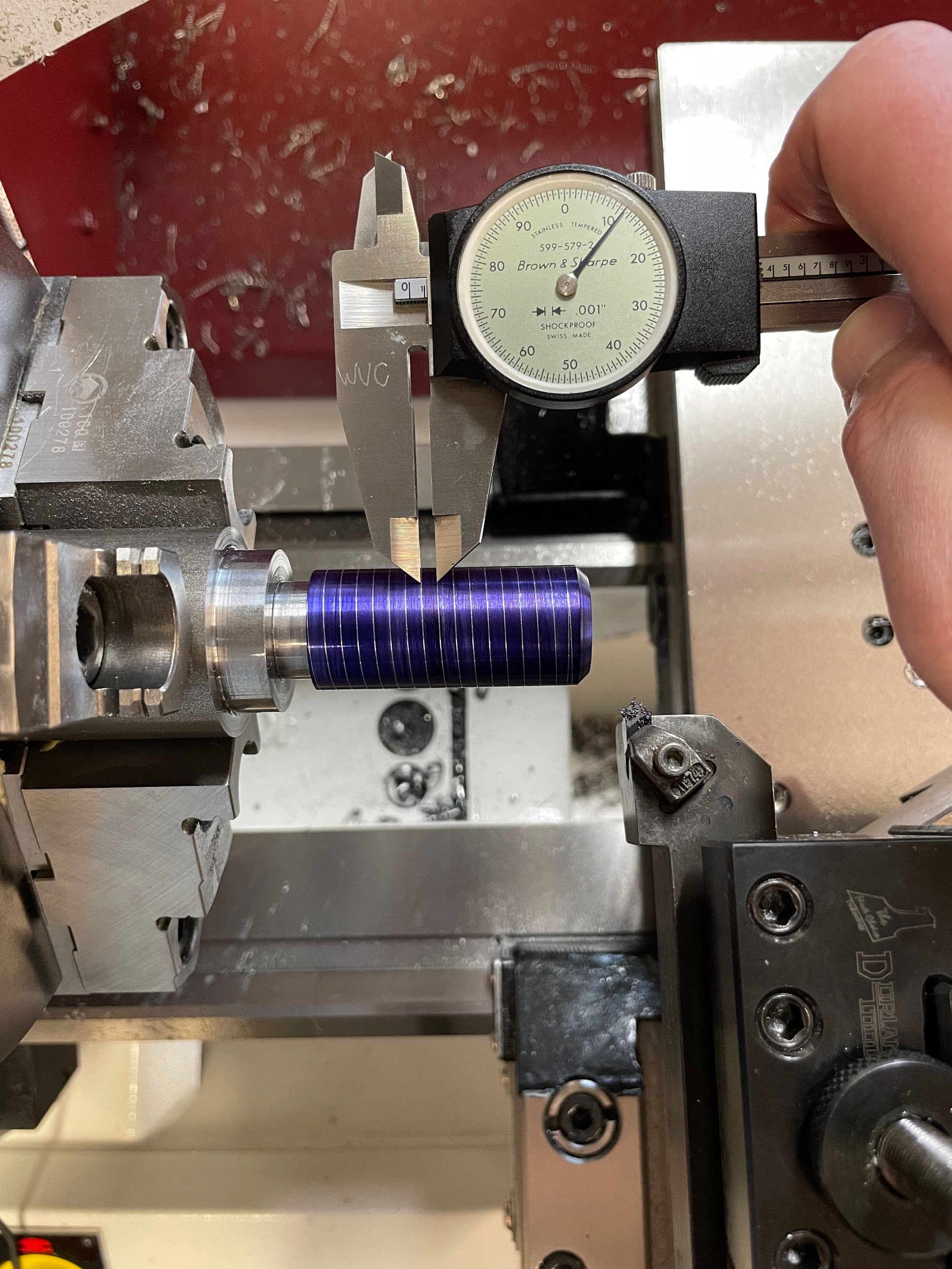
- Use a thread pitch gage or a pair of calipers to check that the threads are the correct TPI.
- Adjust the compound rest to about .010, add oil to the vee groove, and make another cut in the same fashion as the scratch cut. Generally, the first .040 or so can be made .010 at a time. After that, the chip created starts to become really large, and reducing the depth of cut is recommended.
- Continue the thread cutting process and stop when the width of the thread vee surpasses the width of the crest.
- Execute a dwell cut (also known as a zero cut or spring cut) of the threads. This is accomplished by making the cutting motion again, but without advancing the compound rest. Basically, following the same path as the last cut allows the tool to remove any material that may have been left due to the setup of the machine deflecting. This should be done before each measurement and after the last cut.
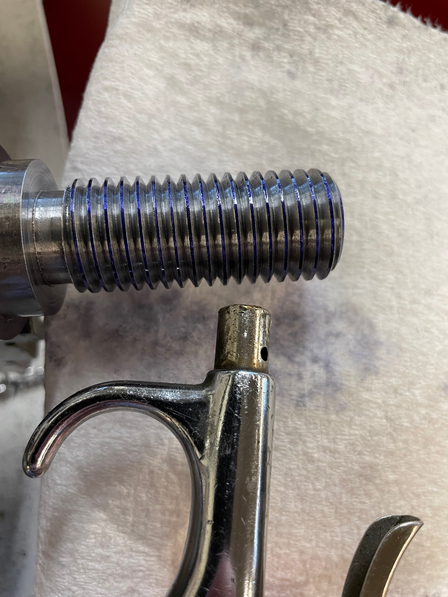
- Thoroughly clean the threads of chips and oil.
- Inspect the flank of the threads for tearing. Now is the opportunity to fix an issue like this.
- Measure the pitch diameter of the threads and compare the measurement to the correct pitch diameter range to determine the material left to be removed.
- Continue cutting threads deeper until reaching a point of within .005 of the pitch diameter range. It is important to note that the compound rest movement is measured as the actual distance, whereas the cross slide movement is measured by the diameter change. It is easy to over-cut threads by not understanding this fact. If the crest of the threads becomes sharp and without a flat, the threads have been cut too far.
- At this point in the thread cutting process, the remaining material is removed by advancing the cross slide in smaller finish cut increments. This allows both sides of the 60 degree cutting tool to cut evenly and create smooth, symmetrical flanks.
- Take the final measurement.
- Gently deburr the crest and the end of the thread.
Step 3: Load a 60 degree threading tool into a tool holder and onto the tool post of the lathe and set the height.
Step 4: Adjust the angle of the compound rest so that it is pointing 29 degrees from being perpendicular to the work. It is important to note that the compound rest should not be set to 29 degrees. This is the angle at which the tool will be advancing for the depth of cut. The reason for the angle is so that the tool cuts a majority of the material from the leading edge of the tool and the chip has room to flow across the chip tool interface. If the depth of cut were to be made strictly perpendicular to the work, the chip would try to form equally from both sides of the cutting tool and bunch up near the fragile tip and potentially break it.
Step 5: Using a center gage, make sure the tool is pointed perpendicular to the work.
Step 7: Using the quick change gear box, select the TPI required.
Step 7: Using the quick change gear box, select the TPI required.
Step 9: Apply layout dye to the outside of the portion to be threaded.
Step 11: Move the cross slide so that the tool is as close as it will get to the work with the handle of the handwheel in the three o’clock position.
Step 12: Set the graduated collar on the cross slide to zero.

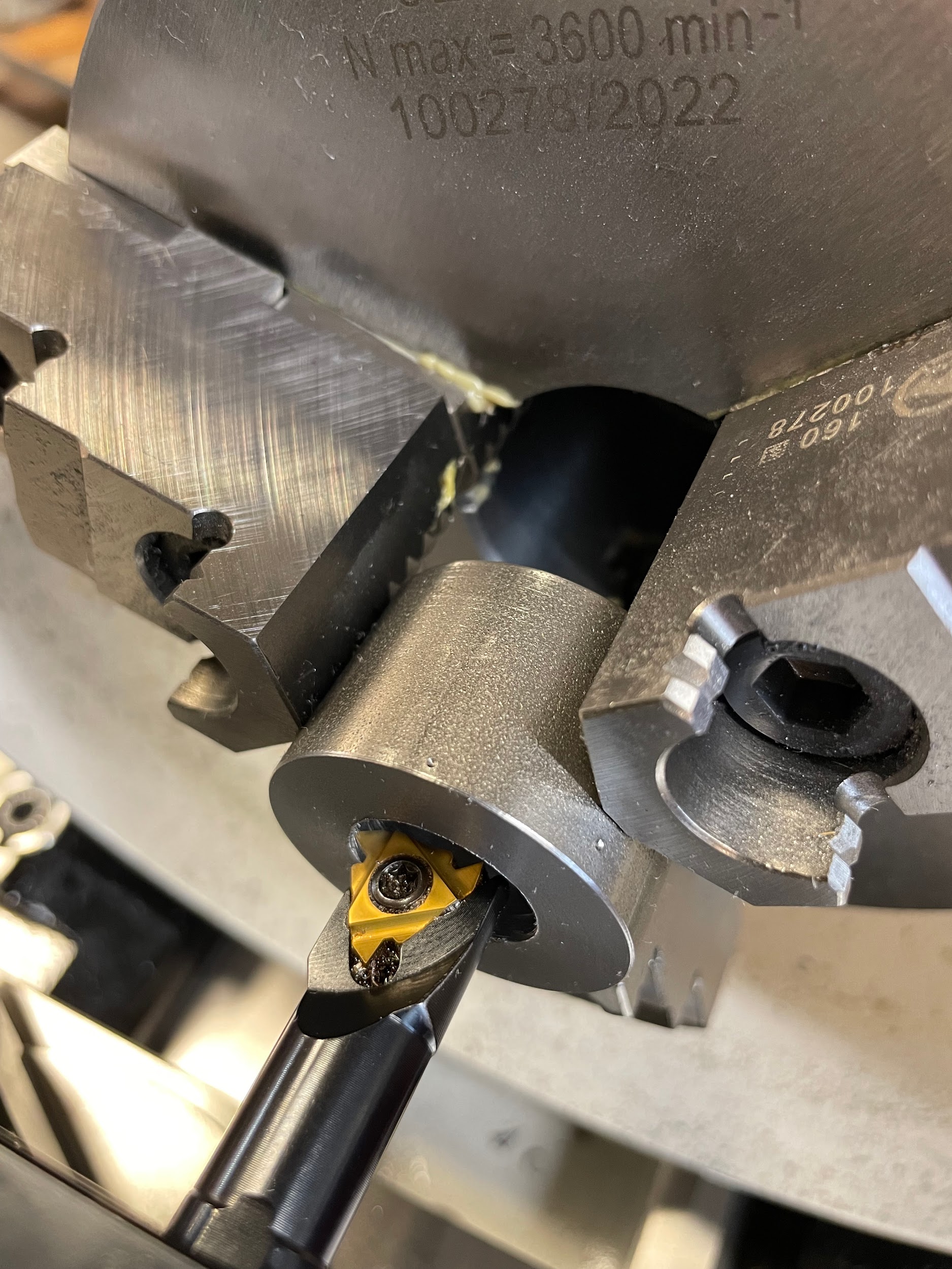
Step 13: Adjust the compound rest so that the tool just touches the outside of the work.
Step 13: Adjust the compound rest so that the tool just touches the outside of the work.

Step 14: Zero the graduated collar on the compound rest.
Step 14: Zero the graduated collar on the compound rest.

Step 17: Select a timing mark or series of marks to engage the half nut lever.
Step 20: Engage the half nut and keep a hand on the lever. Make sure it is fully engaged and on the correct timing mark.
Step 20-21: Engage the half nut and keep a hand on the lever. Make sure it is fully engaged and on the correct timing mark. Watch the tool cut along the outside of the shaft. Once the tool has reached the scribe mark, quickly pull out one full turn of the cross slide with the left hand and then disengage the half nut lever with the right hand. This motion needs to happen quickly and precisely in order to not overtravel the designated thread length or put grooves in the threaded section. Pulling out first is the safest option whenever needing to end the thread cutting operation.

Step 21: Watch the tool cut along the outside of the shaft. Once the tool has reached the scribe mark, quickly pull out one full turn of the cross slide with the left hand and then disengage the half nut lever with the right hand. This motion needs to happen quickly and precisely in order to not overtravel the designated thread length or put grooves in the threaded section. Pulling out first is the safest option whenever needing to end the thread cutting operation.

Step 24: Use a thread pitch gage or a pair of calipers to check that the threads are the correct TPI.
Step 25: Adjust the compound rest to about .010, add oil to the vee groove, and make another cut in the same fashion as the scratch cut. Generally, the first .040 or so can be made .010 at a time. After that, the chip created starts to become too large, and reducing the depth of cut is recommended.

Step 26: Continue the thread cutting process and stop when the width of the thread vee surpasses the width of the crest.

Step 27: Execute a dwell cut (also known as a zero cut or spring cut) of the threads. This is accomplished by making the cutting motion again, but without advancing the compound rest. Basically, following the same path as the last cut allows the tool to remove any material that may have been left due to the setup of the machine deflecting. This should be done before each measurement and after the last cut.

Step 28: Thoroughly clean the threads of chips and oil.
Step 30: Measure the pitch diameter of the threads and compare the measurement to the correct pitch diameter range to determine the material left to be removed.
Step 31: Continue cutting threads deeper until reaching a point within .005 of the pitch diameter range. It is important to note that the compound rest movement is measured as the actual distance, whereas the cross slide movement is measured by the diameter change. It is easy to over-cut threads by not understanding this fact. If the crest of the threads becomes sharp and without a flat, the threads have been cut too far.
Step 32: At this point in the thread cutting process, the remaining material is removed by advancing the cross slide in smaller finish cut increments. This allows both sides of the 60 degree cutting tool to cut evenly and create smooth, symmetrical flanks.
Step 32: At this point in the thread cutting process, the remaining material is removed by advancing the cross slide in smaller finish cut increments. This allows both sides of the 60 degree cutting tool to cut evenly and create smooth, symmetrical flanks. ”

Step 33: Take the final measurement.

Step 34: Gently deburr the crest and the end of the thread.
Step by step process for internal threading:
- Drill, and or, bore a hole to the minor diameter in the area to be threaded. The minor diameter and tolerance for any thread can be looked up in a manufacturing reference book.
- Chamfer the face end of the shaft to be threaded. The size of this chamfer should be out to the major diameter.
- Adjust the angle of the compound rest so that it is pointing 29 degrees from the operator. It is important to note that the compound rest should not be set to 29 degrees. This is the angle at which the tool will be advancing for the depth of cut. The reason for the angle is so that the tool cuts a majority of the material from the leading edge of the tool and the chip has room to flow across the chip tool interface. If the depth of cut were to be made strictly perpendicular to the work, the chip would try to form equally from both sides of the cutting tool and bunch up near the fragile tip and potentially break it.
- Square the tool post.
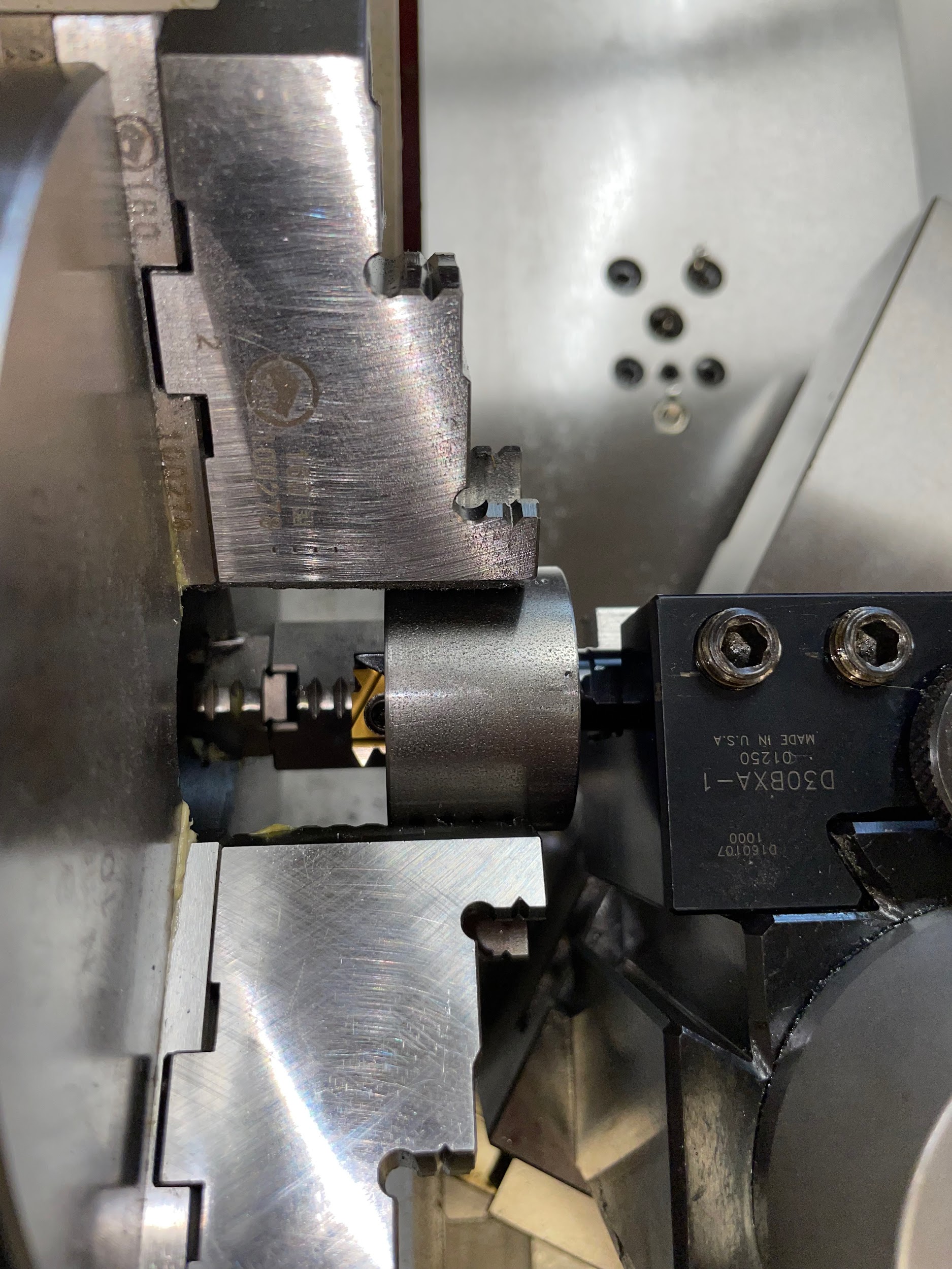
- Load a 60 degree threading bar into a tool holder and onto the tool post of the lathe. Only have the bar out as far as is needed, with 1/8″ of clearance, to combat chatter.
- Using a center gage, make sure the tool is pointed perpendicular to the work.
- Select a slow spindle speed for threading, generally about 100 RPMs for beginners. On a gear head lathe, once the threading process has been started, the spindle speed can not be altered without ruining the alignment of the thread.
- Using the quick change gear box, select the TPI required.
- Turn the spindle on and make sure the machine is in gear and that the lead screw is turning.
- Apply layout dye to the threading bar at approximately the depth of the thread. (Blind thread only.)
- With odd leg calipers, scribe a line on the threading bar at the point where the thread will end. (Blind thread only.)
- Move the cross slide so that the tool is as close as it will get to the inside diameter with the handle of the hand wheel in the nine o’clock position.
- Set the graduated collar on the cross slide to zero.
- Adjust the compound rest so that the tool just touches the inside of the work.
- Zero the graduated collar on the compound rest.
- Move the carriage to about 1/2″ in front of the part.
- Advance the compound rest a couple of thousandths to make a scratch pass for thread inspection.
- Select a timing mark or series of marks to engage the half nut lever.
- With a brush, spread cutting oil on the inside of the hole.
- Place the left hand on the cross slide handle, being prepared to push out of the thread.
- Engage the half nut and keep a hand on the lever. Make sure it is fully down and on the correct timing mark.
- Watch the tool cut along the outside of the shaft. Once the cutting edge is through the part (for blind holes, once the face of the work has reached the scribe mark), quickly push out one full turn of the cross slide with the left hand, and then disengage the half nut lever with the right hand. This motion needs to happen quickly and precisely in order to not overtravel the designated thread length, or put grooves in the threaded section. Pulling out first is the safest option whenever needing to end the thread cutting operation.
- Move the carriage to the front of the thread again.
- Reset the cross slide to the zero and nine o’clock position.
- Use a thread pitch gage or a pair of calipers to check if the threads are the correct TPI.
- Adjust the compound rest to about .010, add oil to the vee groove, and make another cut in the same fashion as the scratch cut. Generally, the first .040 or so can be made .010 at a time. After that, the chip created starts to become really large, and reducing the depth of cut is recommended.
- Continue the thread cutting process and stop when the width of the thread vee is equal to that of the crest.
- Execute a dwell cut (also known as a zero cut or spring cut) of the threads. This is accomplished by making the cutting motion again, but without advancing the compound rest. Basically, following the same path as the last cut allows the tool to remove any material that may have been left due machine setup deflection. This should be done before each measurement and after the last cut.
- Thoroughly clean the threads of chips and oil.
- Inspect the flank of the threads for tearing. Now is the opportunity to fix tears and similar problems.
- Check the thread by attempting to insert a bolt into the hole. The bolt will be smaller than the threaded plug gage and will start into the hole sooner. It is also nice to test with a bolt so the expensive threaded plug gage doesn’t get damaged from overuse or accidents.
- Continue cutting threads deeper until the bolt starts to thread into the hole. It is important to note that the compound rest movement is measured as the actual distance, whereas the cross slide movement is measured by the diameter change. It is easy to over-cut threads by not understanding this fact. If the crest of the threads becomes sharp and without a flat, the threads have been cut too far.
- Check with a threaded plug gage from this step on.
- At this point in the thread cutting process, the remaining material is removed by advancing the cross slide in smaller finish cut increments. This allows both sides of the 60 degree cutting tool to cut evenly and create smooth, symmetrical flanks.
- Gently deburr the crest and the end of the thread.
Step 1: Drill, and or, bore a hole to the minor diameter in the area to be threaded. The minor diameter and tolerance for any thread can be looked up in a manufacturing reference book.

Step 1: Drill, and or, bore a hole to the minor diameter in the area to be threaded. The minor diameter and tolerance for any thread can be looked up in a manufacturing reference book.
Step 1: Drill, and or, bore a hole to the minor diameter in the area to be threaded. The minor diameter and tolerance for any thread can be looked up in a manufacturing reference book.

Step 1: Drill, and or, bore a hole to the minor diameter in the area to be threaded. The minor diameter and tolerance for any thread can be looked up in a manufacturing reference book.

Step 4: Square the tool post.
Step 4: Square the tool post.
Step 5: Load a 60 degree threading bar into a tool holder and onto the tool post of the lathe. Only have the bar out as far as is needed, with 1/8″ of clearance, to combat chatter.
Step 5: Load a 60 degree threading bar into a tool holder and onto the tool post of the lathe. Only have the bar out as far as is needed, with 1/8″ of clearance, to combat chatter.
Step 5: Load a 60 degree threading bar into a tool holder and onto the tool post of the lathe. Only have the bar out as far as is needed, with 1/8″ of clearance, to combat chatter.
Step 6: Using a center gage, make sure the tool is pointed perpendicular to the work.
Step 13: Set the graduated collar on the cross slide to zero.
Step 14: Adjust the compound rest so that the tool just touches the inside of the work.
Step 15: Zero the graduated collar on the compound rest.
Step 21-22: Engage the half nut and keep a hand on the lever. Make sure it is fully down and on the correct timing mark. Watch the tool cut along the outside of the shaft. Once the cutting edge is through the part (for blind holes, once the face of the work has reached the scribe mark), quickly push out one full turn of the cross slide with the left hand and then disengage the half nut lever with the right hand. This motion needs to happen quickly and precisely in order to not overtravel the designated thread lengt, or put grooves in the threaded section. Pulling out first is the safest option whenever needing to end the thread cutting operation.

Step 31: Check the thread by attempting to insert a bolt into the hole. The bolt will be smaller than the threaded plug gage and will start into the hole sooner. It is also nice to test with a bolt, so the expensive threaded plug gage doesn’t get damaged from overuse or accidents.

Thread Measurement
Measuring threads can be accomplished by a few different methods. Fixed gages, known as threaded ring and threaded plug gages, are an easy way to check both thread size and form. Thread micrometers are very accurate, but they are often costly and require measuring skills to read. Lastly, there are thread wires. Thread wires can only measure external threads; however, they are the cheapest option because they utilize existing measuring equipment. Thread wires are also the most complicated to use because there are multiple pieces to manipulate, and there is math involved in taking a measurement.
Threaded ring and plug gages
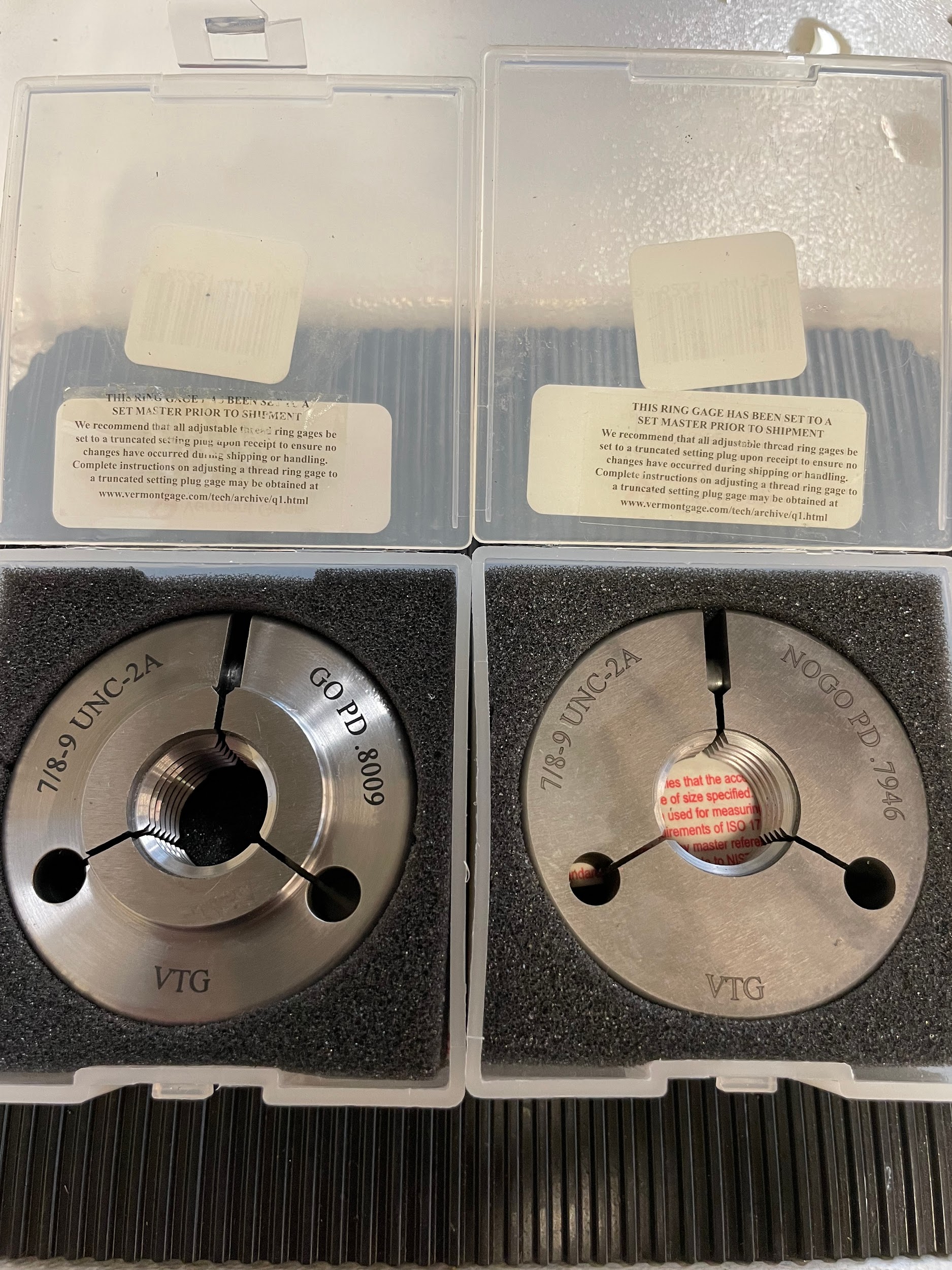
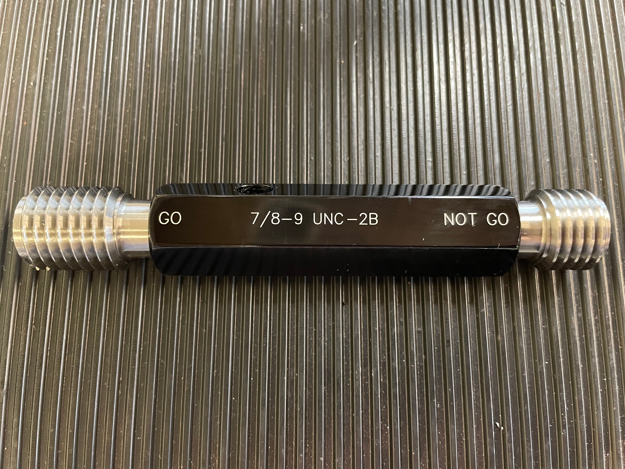
Threaded ring gages and threaded plug gages will not measure the size of the threads, they will only indicate if the part is bigger or smaller than the gage. For this reason, they are good for checking both ends of the pitch diameter tolerance zone and distinguishing conforming from non-conforming parts for inexperienced operators. One drawback is that different gages are needed to check each size of thread. That can become expensive if many sizes are required.
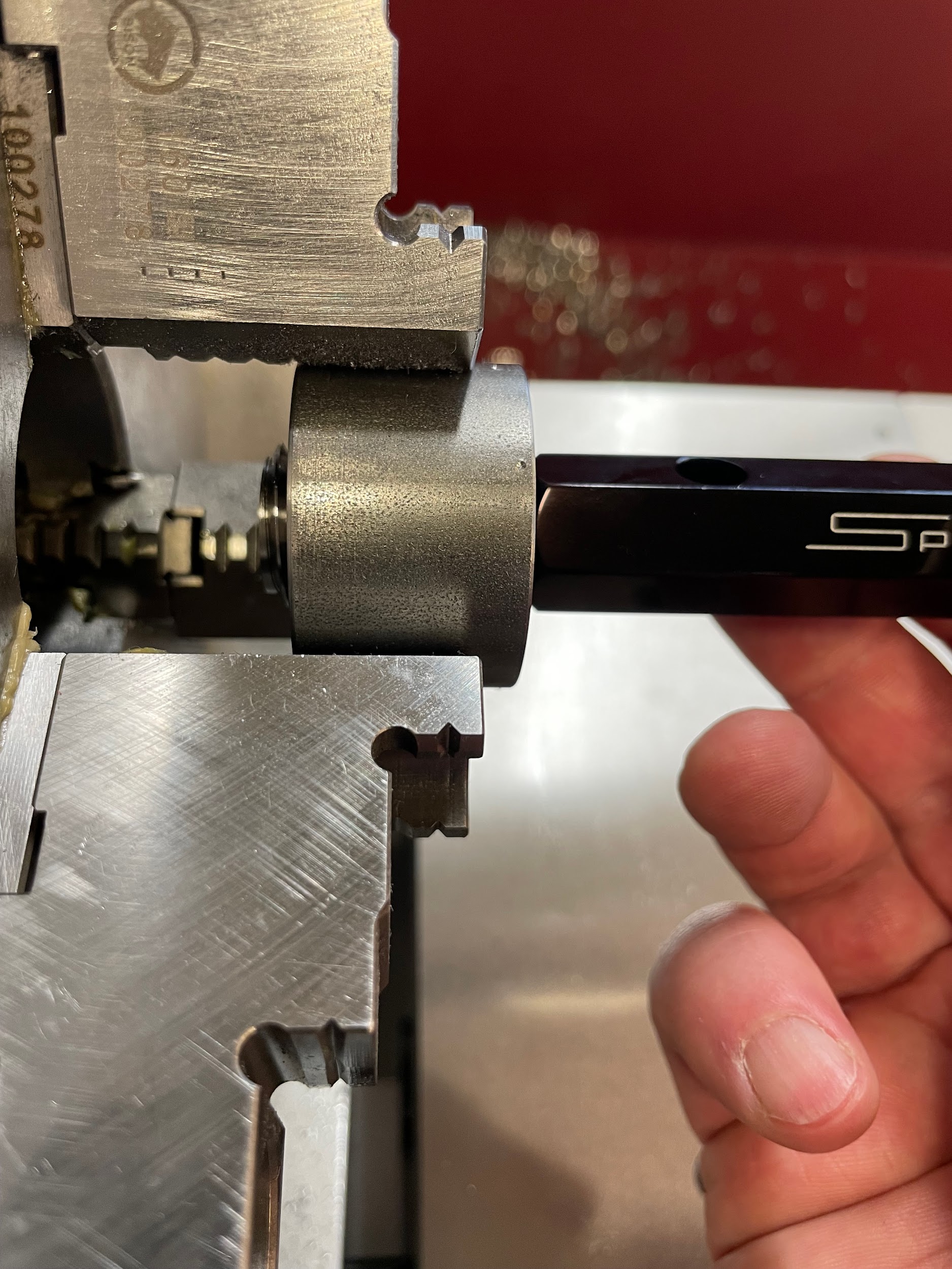
- Clean the threads thoroughly.
- Apply a small amount of gage oil to the “go” fixed gage. This gage would be the maximum allowable pitch diameter for an external thread, and the minimum allowable pitch diameter for an internal thread.
- Delicately screw the gage onto or into the part. Stop if there is any resistance. This gage is not designed to cut, clean, or debur threads; it only measures them. If the gage goes on or in fully, then enough material has been removed to be within the pitch diameter tolerance. This result means the part may be good. If the gage doesn’t go onto or into the part, then it should be reworked to be within pitch diameter tolerance.
- Remove and clean gage.
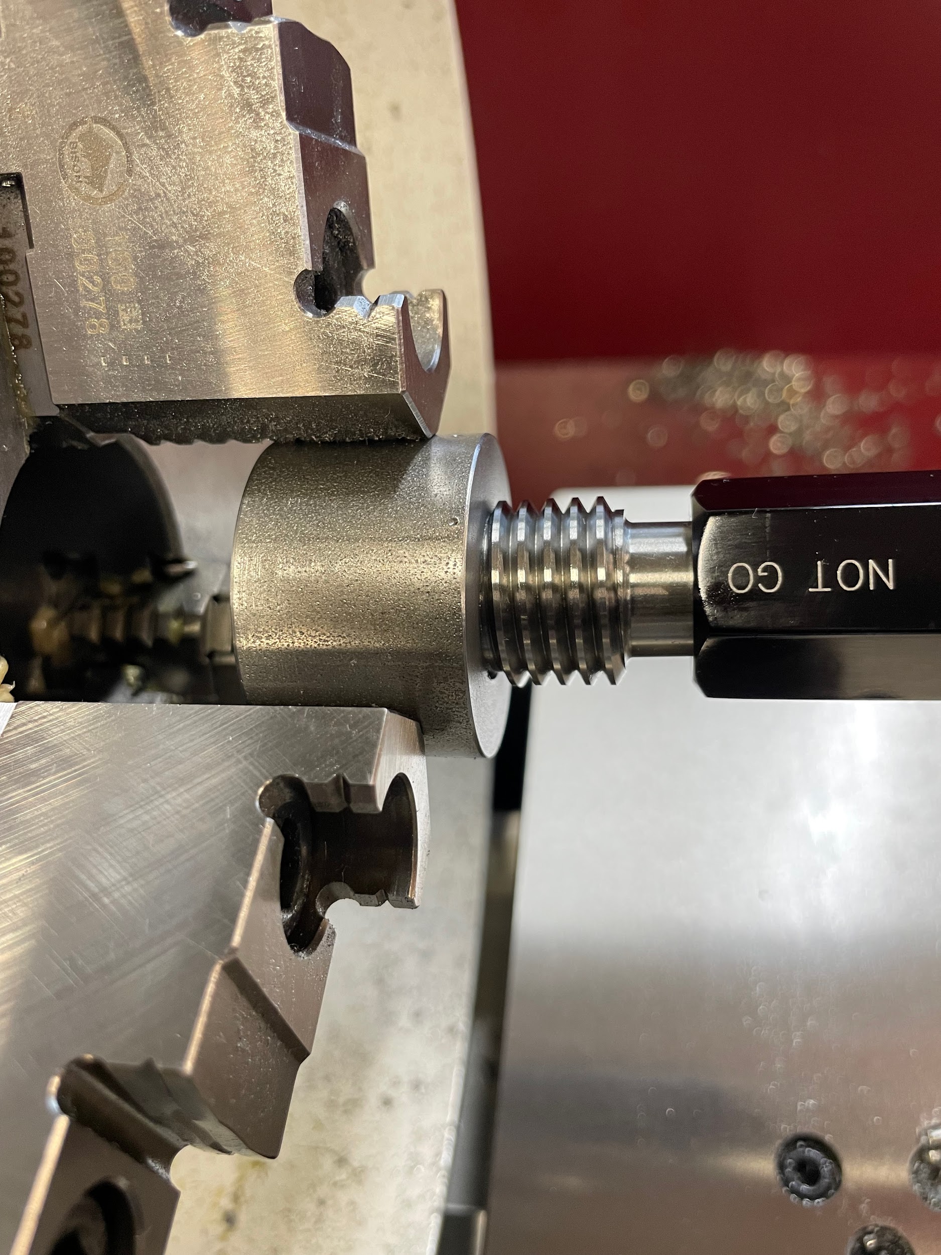
- Apply a small amount of gage oil to the “no-go” fixed gage. This gage would be the minimum allowable pitch diameter for an external thread and the maximum allowable pitch diameter for an internal thread.
- Delicately screw the gage onto or into the part. Stop if there is any resistance. This gage is designed to go on by no more than one thread and stop. If the gage doesn’t thread onto or into the part, then enough material is remaining to be within the pitch diameter tolerance. This result indicates that the part may be good. If the gage goes onto or into the part fully, then the part has had too much material removed, and the part is scrap.
- Remove and clean gage.
Step 3: Delicately screw the gage onto or into the part. Stop if there is any resistance. This gage is not designed to cut, clean, or debur threads; it only measures them. If the gage goes on or in fully, then enough material has been removed to be within the pitch diameter tolerance. This result means the part may be good. If the gage doesn’t go onto or into the part, then it should be reworked to be within pitch diameter tolerance.”

Step 3: Delicately screw the gage onto or into the part. Stop if there is any resistance. This gage is not designed to cut, clean, or debur threads; it only measures them. If the gage goes on or in fully, then enough material has been removed to be within the pitch diameter tolerance. This result means the part may be good. If the gage doesn’t go onto or into the part, then it should be reworked to be within pitch diameter tolerance.
Step 6: Delicately screw the gage onto or into the part. Stop if there is any resistance. This gage is designed to go on by no more than one thread and stop. If the gage doesn’t thread onto or into the part, then enough material is remaining to be within the pitch diameter tolerance. This result indicates that the part may be good. If the gage goes onto or into the part fully, then the part has had too much material removed, and the part is scrap.

Step 6: Delicately screw the gage onto or into the part. Stop if there is any resistance. This gage is designed to go on by no more than one thread and stop. If the gage doesn’t thread onto or into the part, then enough material is remaining to be within the pitch diameter tolerance. This result indicates that the part may be good. If the gage goes onto or into the part fully, then the part has had too much material removed, and the part is scrap.
Thread micrometer
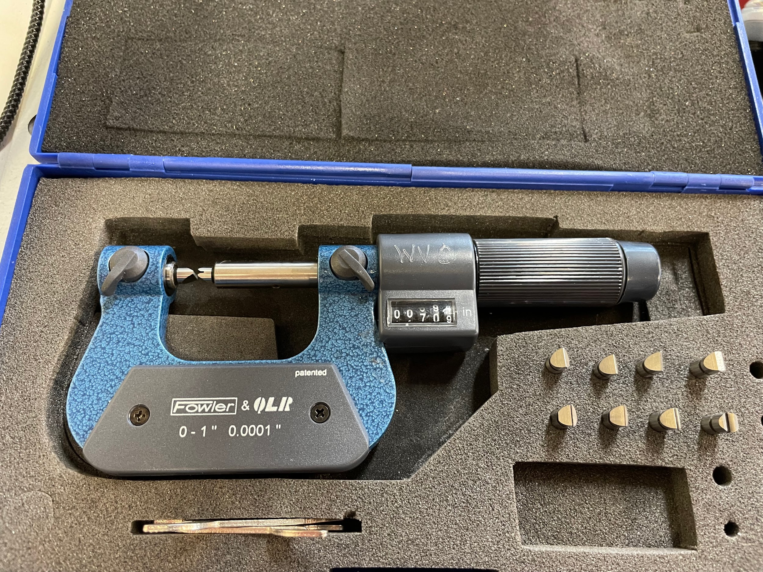
Thread micrometers are an excellent way to check parts. Although fairly expensive, thread micrometers come in inch increments, some with interchangeable anvils, and can measure many threads within their range. Thread micrometers also offer direct readings for ease of use. Anyone who can read a regular micrometer can read a thread micrometer.
- Clean the threads thoroughly.
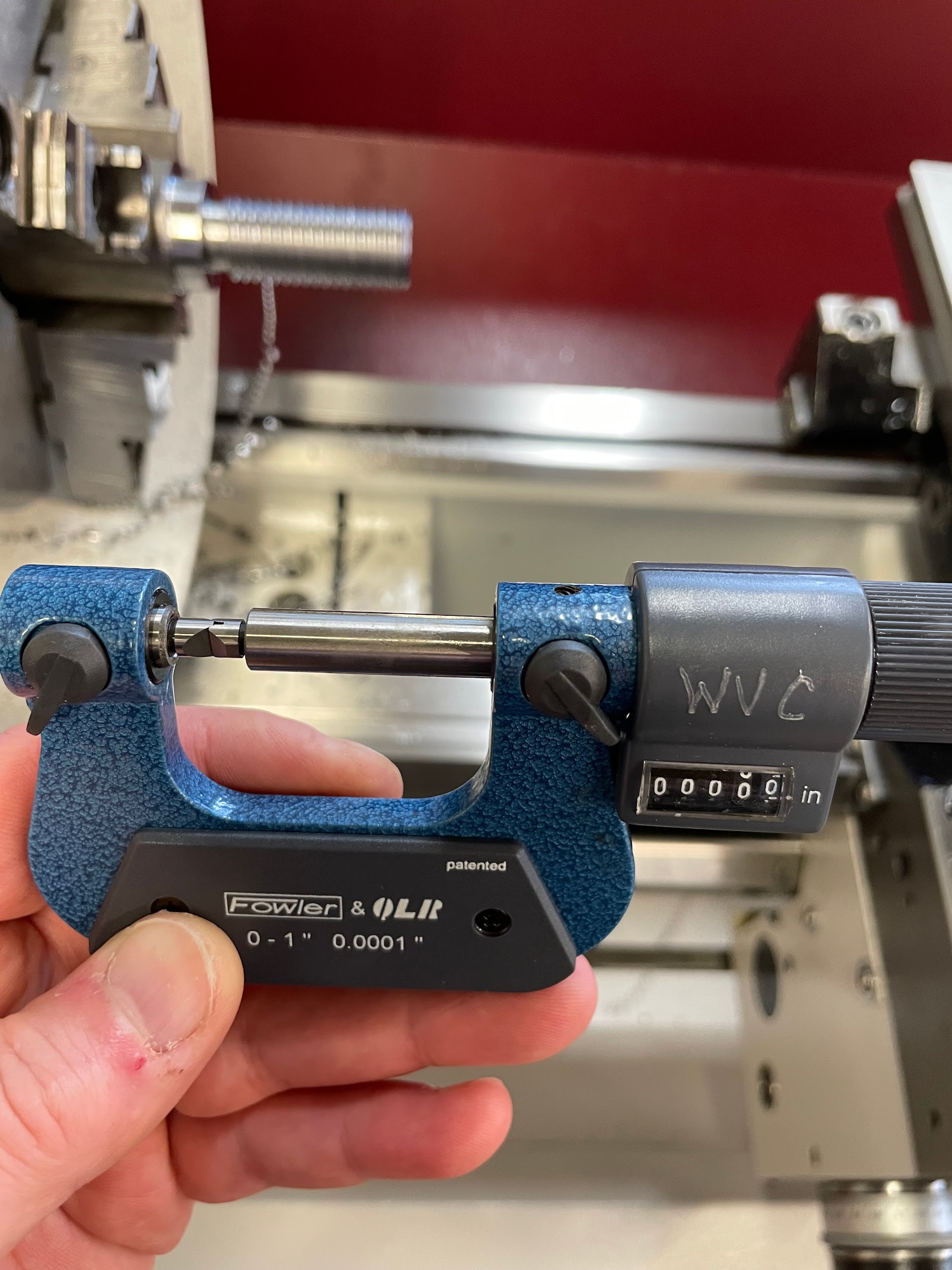
- Remove the thread micrometer from the case, clean, install the correct anvils, and calibrate.
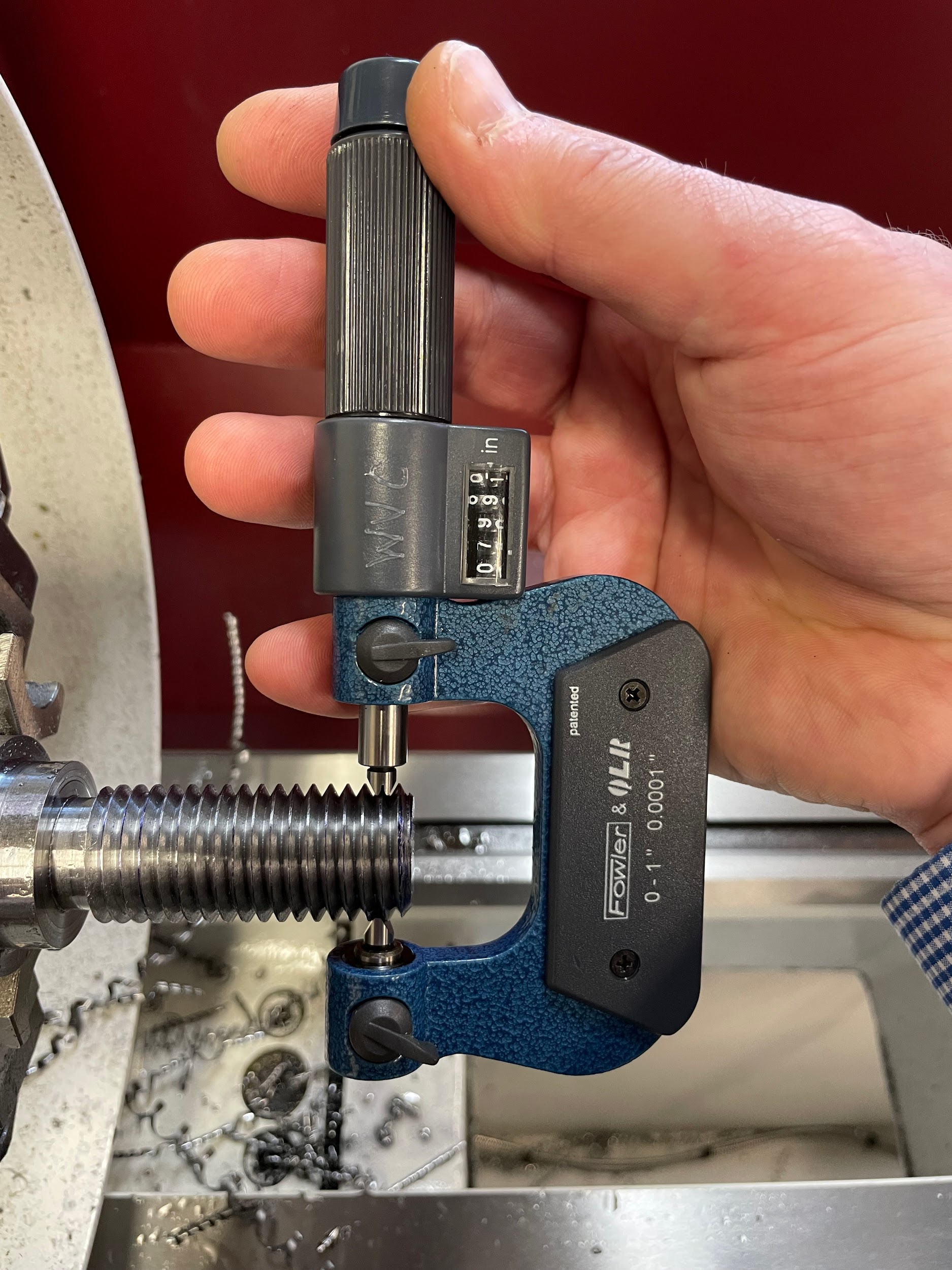
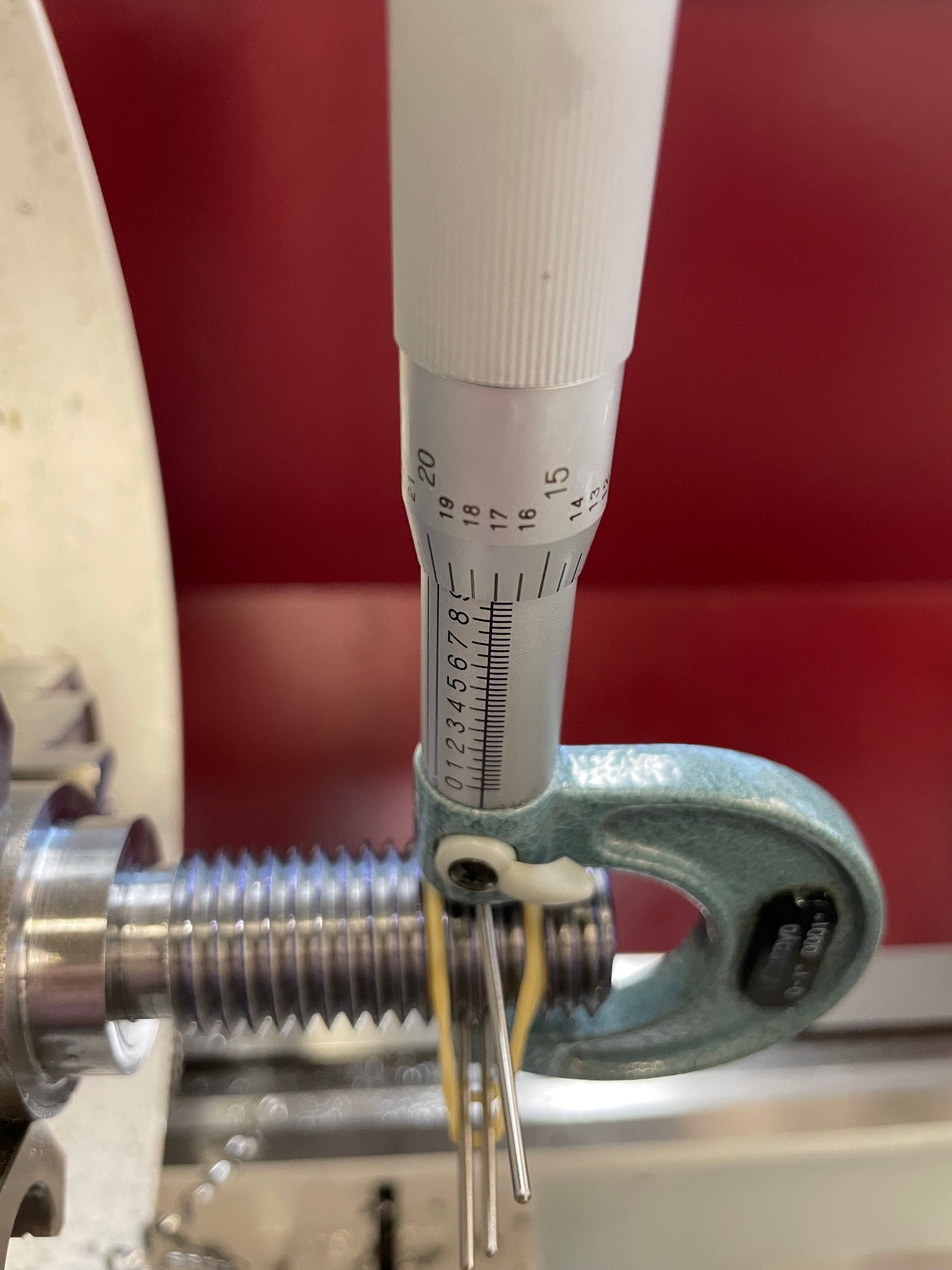
- Measure the thread by inserting the concave vee anvil over a single thread and the convex fee anvil in between two threads. Adjust the thimble of the thread micrometer onto the thread and take the reading.
- Compare the reading on the micrometer to the pitch diameter tolerance in a manufacturing reference book.
Step 2: Remove the thread micrometer from the case, clean, install the correct anvils, and calibrate.
Step 3: Measure the thread by inserting the concave vee anvil over a single thread and the convex fee anvil in between two threads. Adjust the thimble of the thread micrometer onto the thread and take the reading.
Thread wires
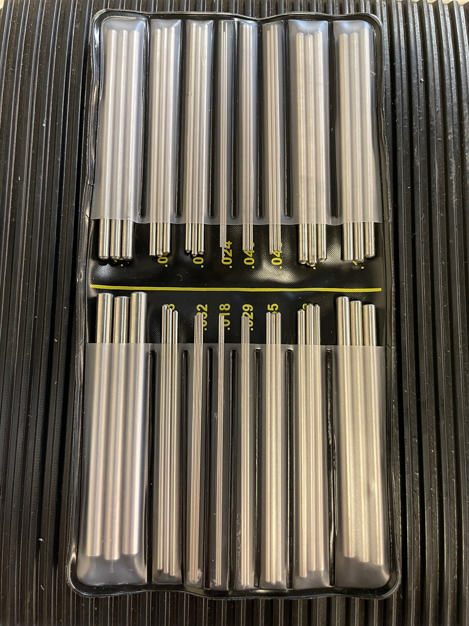
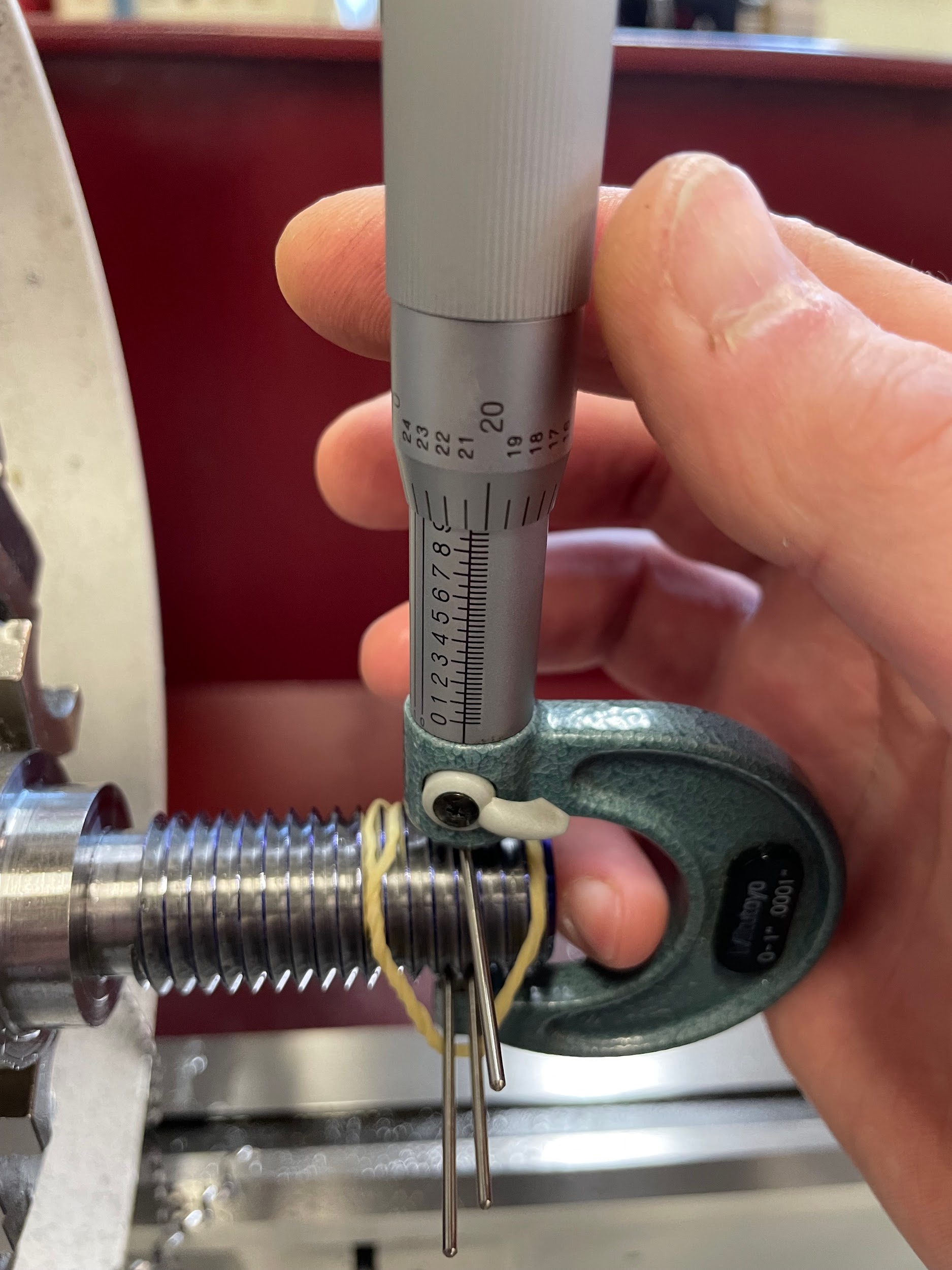
The three wire method of reading threads is a convenient and cost-effective way for anyone to measure threads. The reason it is so economical is because the measuring kit only consists of multiple 3 wire sets and utilizes existing micrometers for measuring. It can be a little tricky to manipulate all the wires and a micrometer with only two hands, but with a little practice it becomes easier.
The following formula converts the measurement taken with a micrometer over the wires into the pitch diameter. The pitch diameter can then be compared to the pitch diameter tolerance in a manufacturing reference book.
Pitch Diameter = Measurement – Constant
The constant in this formula refers to a known value in the thread wire instructions. Each size of thread wires has a different constant. (Insert picture of thread wire chart.)
For example, if attempting to measure 9/16 – 12 2A threads, the pitch diameter tolerance would be .5016 to .5068 (from reference book) and the constant would be .09283 (from thread wire instructions) because of the .055 thread wire required to measure a 12 TPI thread. If a measurement was taken over the wires at .5971, the math would be as follows:
Pitch Diameter = Measurement – Constant
Pitch Diameter = .5971 – .09283
Pitch Diameter = .50427
When compared to the pitch diameter tolerance, it can be seen that the thread is within tolerance.
.5016 < .50427 < .5068
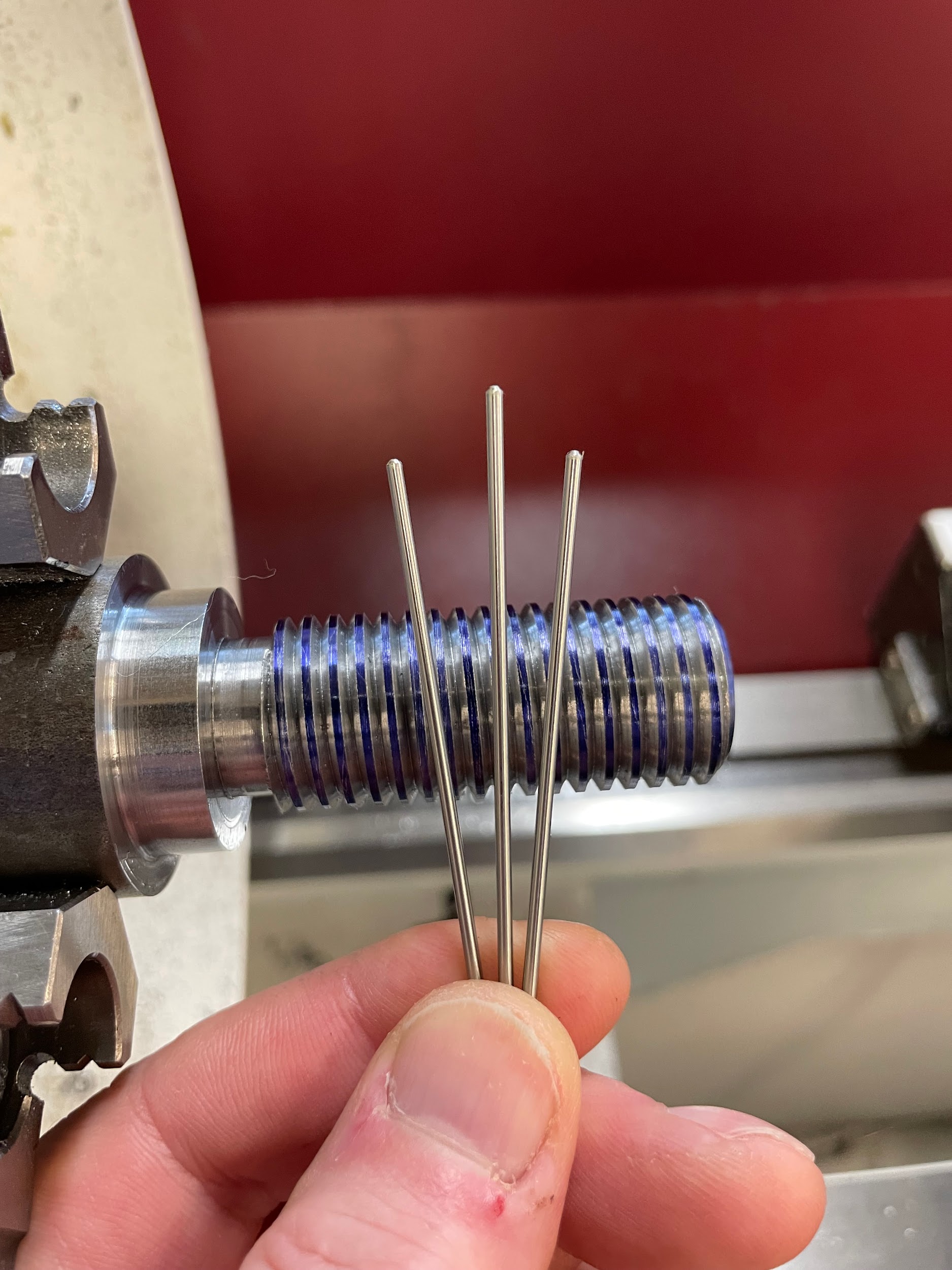
- Refer to the instructions that come in the thread wire kit and select the wire size for the TPI to be measured.
- Select a micrometer that is capable of measuring the nominal diameter of the thread.
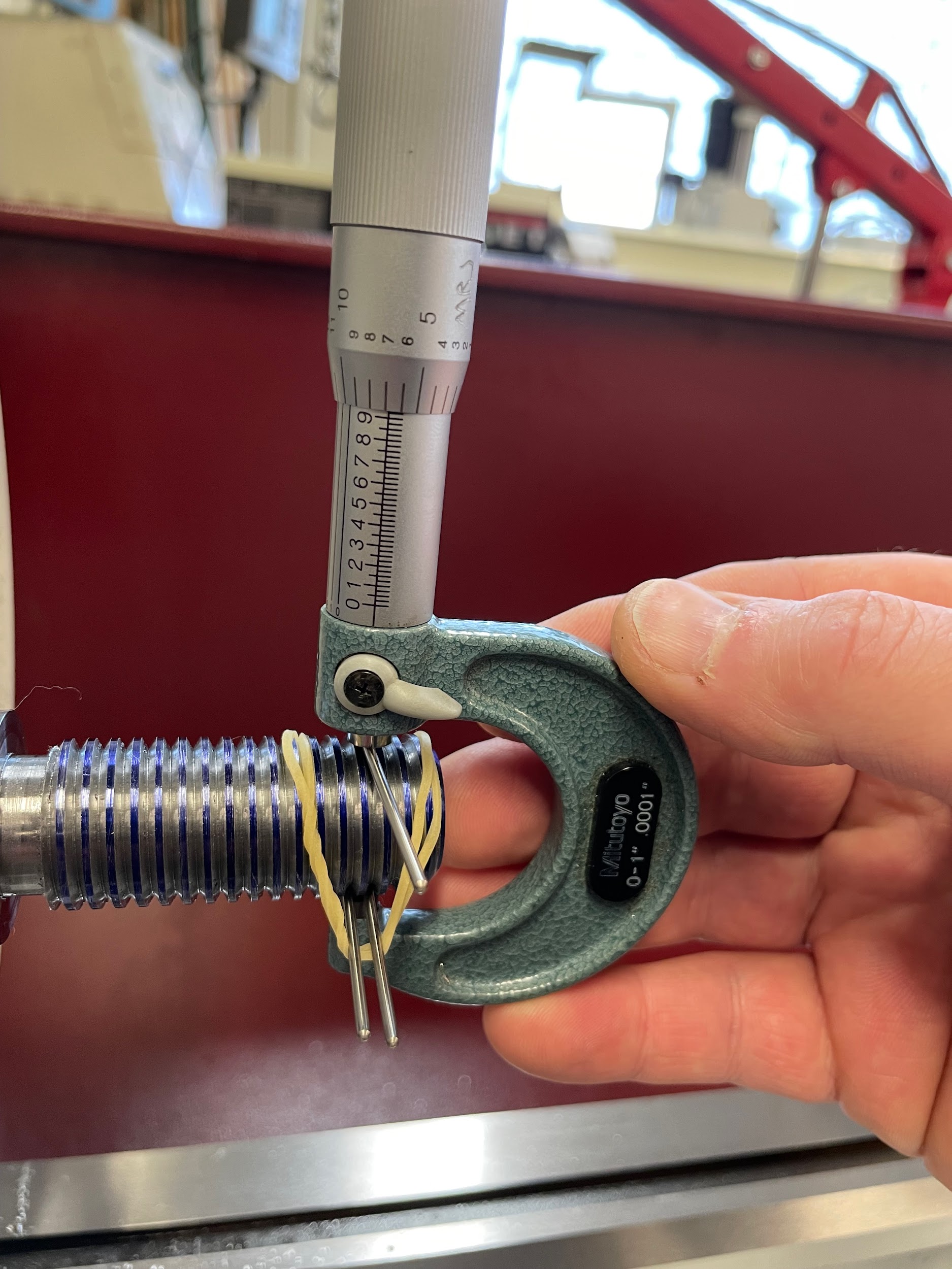
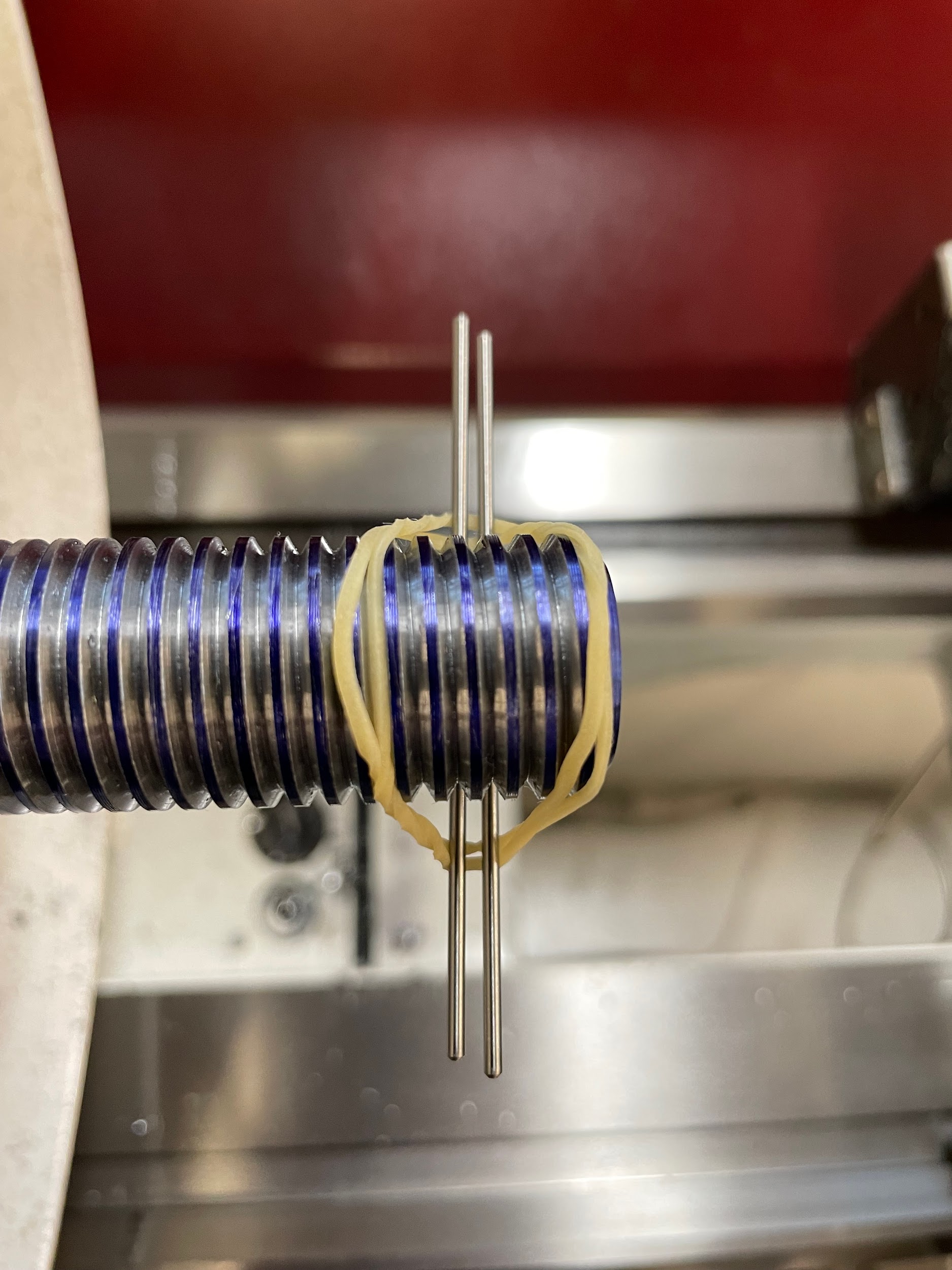
- Use a rubber band to hold two thread wires in grooves underneath the thread, and balance one thread wire in a groove on top of the thread, centered between the bottom two.
- Carefully manipulate the micrometer to take an accurate measurement over the maximum point between the three wires.
- Lock the micrometer and read the measurement.
- Insert this measurement into the formula, along with the constant, to calculate the thread’s pitch diameter.
- Compare the thread cut to the pitch diameter tolerance.
Step 1: Refer to the instructions that come in the thread wire kit and select the wire size for the TPI to be measured.
| THREADS PER INCH | WIRE SIZE | CONST | THREADS PER IN | WIRE SIZE | CONST |
|---|---|---|---|---|---|
| 48 | .018 | .03596 | 11 1/2 | .055 | .09869 |
| 44 | .018 | .03432 | 11 | .055 | .08627 |
| 40 | .018 | .03235 | 10 | .055 | .07840 |
| 36 | .018 | .02994 | 9 | .063 | .09277 |
| 32 | .024 | .04494 | 8 | .072 | .10775 |
| 28 | .024 | .04107 | 7 1/2 | .081 | .12753 |
| 27 | .024 | .03993 | 7 | .081 | .11928 |
| 24 | .029 | .05092 | 6 | .092 | .13166 |
| 20 | .029 | .04370 | 5 1/2 | .108 | .16654 |
| 18 | .032 | .04789 | 5 | .120 | .18679 |
| 16 | .040 | .06587 | 4 1/2 | .127 | .18855 |
| 14 | .040 | .05814 | 4 | .143 | .21249 |
| 13 | .045 | .06838 | 3 1/2 | .185 | .30756 |
| 12 | .055 | .09283 | 3 | .185 | .26632 |
Step 1: Refer to the instructions that come in the thread wire kit and select the wire size for the TPI to be measured.
Step 3: Use a rubber band to hold two thread wires in grooves underneath the thread, and balance one thread wire in a groove on top of the thread, centered between the bottom two.
Step 3: Use a rubber band to hold two thread wires in grooves underneath the thread, and balance one thread wire in a groove on top of the thread, centered between the bottom two.
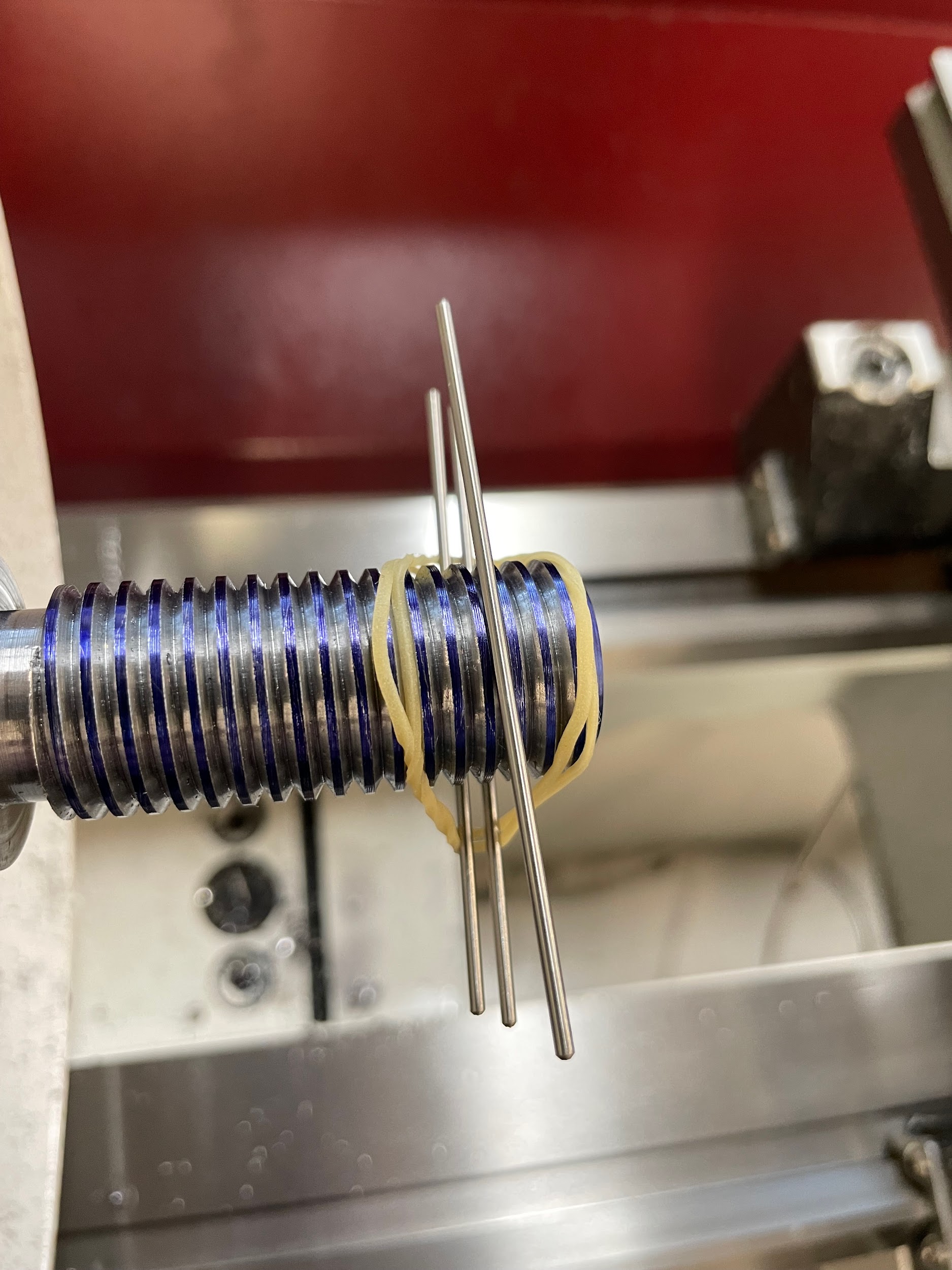
Step 4: Carefully manipulate the micrometer to take an accurate measurement over the maximum point between the three wires.
Author’s Tip
- Timing marks and threading memory challenges: There are many charts that will give information about the correct timing marks that can be engaged for a given thread. Your lathe probably even came with one. They are all correct; however, they are difficult to memorize unless you do a lot of single point threading. Often, in today’s manufacturing environment, repetitive threading jobs are handled on CNC equipment. Manual lathe single point threading is generally left for odd jobs of low quantity. For that reason, I have never been able to remember exactly what threads you can engage on which number.
- A simple whole number approach: When further inspecting one of the half nut timing charts, you will notice that almost every thread can be cut by selecting the same whole number for each cut. So, pick one whole number as a timing mark and stick with it for the whole thread. This method may take a little longer than engaging on multiple points, but it has kept me from scraping threads for many years.
- Internal threads and compound rest depth: For internal threads, it can be difficult to know how much to advance the compound rest without going too deep. When I cut internal threads, I never cut more than the diameter deviation of the pitch diameter, and then I check depth after each cut. That means that if I am not within the pitch diameter range and I only move in the amount of the pitch diameter range difference, it is impossible to overcut the thread.
- Mastering timing and synchronous hand movements: Complex timing and synchronous hand movements are difficult to master and always a challenge no matter how much experience you have. For that reason, I always practice off the part. Have spots in mind where you will be engaging the half nut, pulling out, and disengaging the half nut. Practice it over and over until you can make the motion reliably every time. For beginners, I suggest practicing until you can do it at least ten times in a row.
Author’s Tip
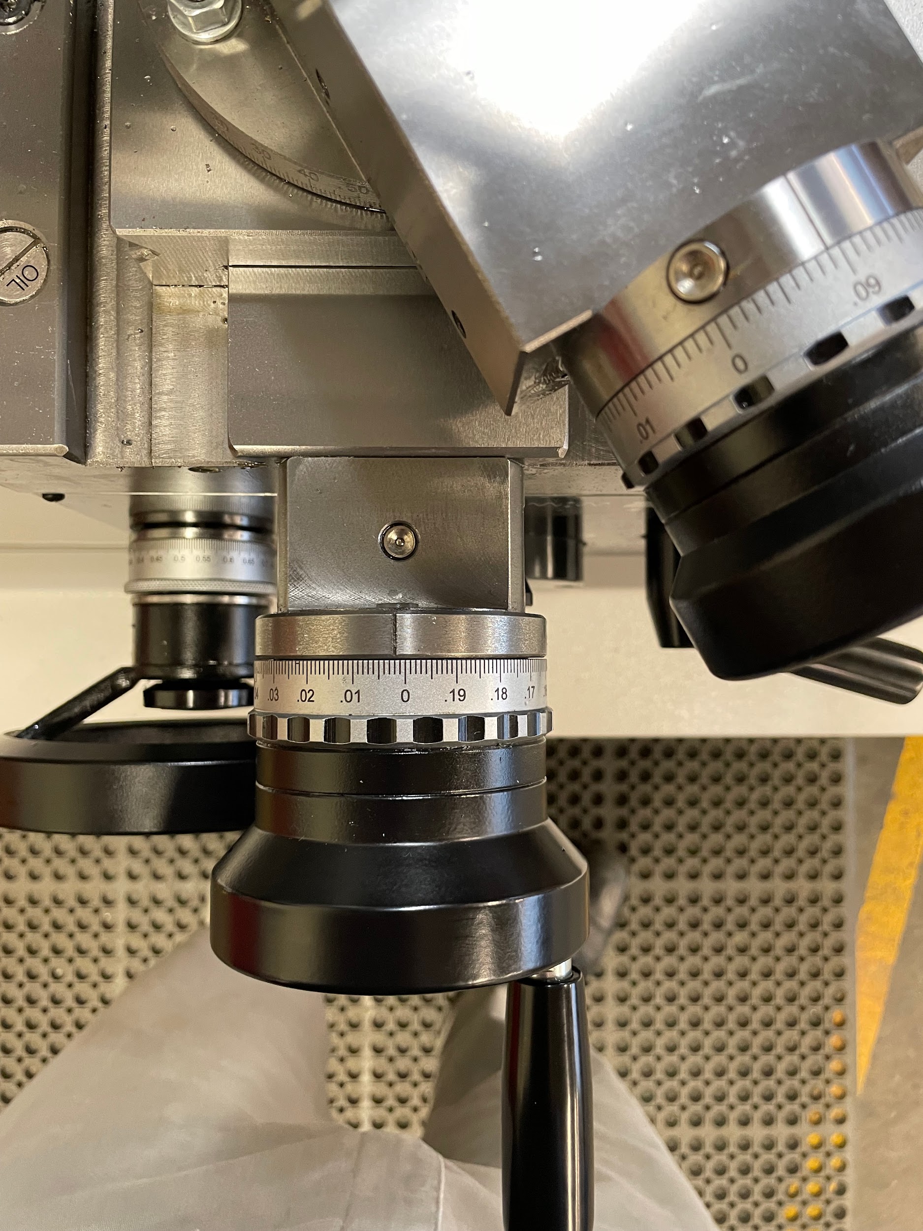
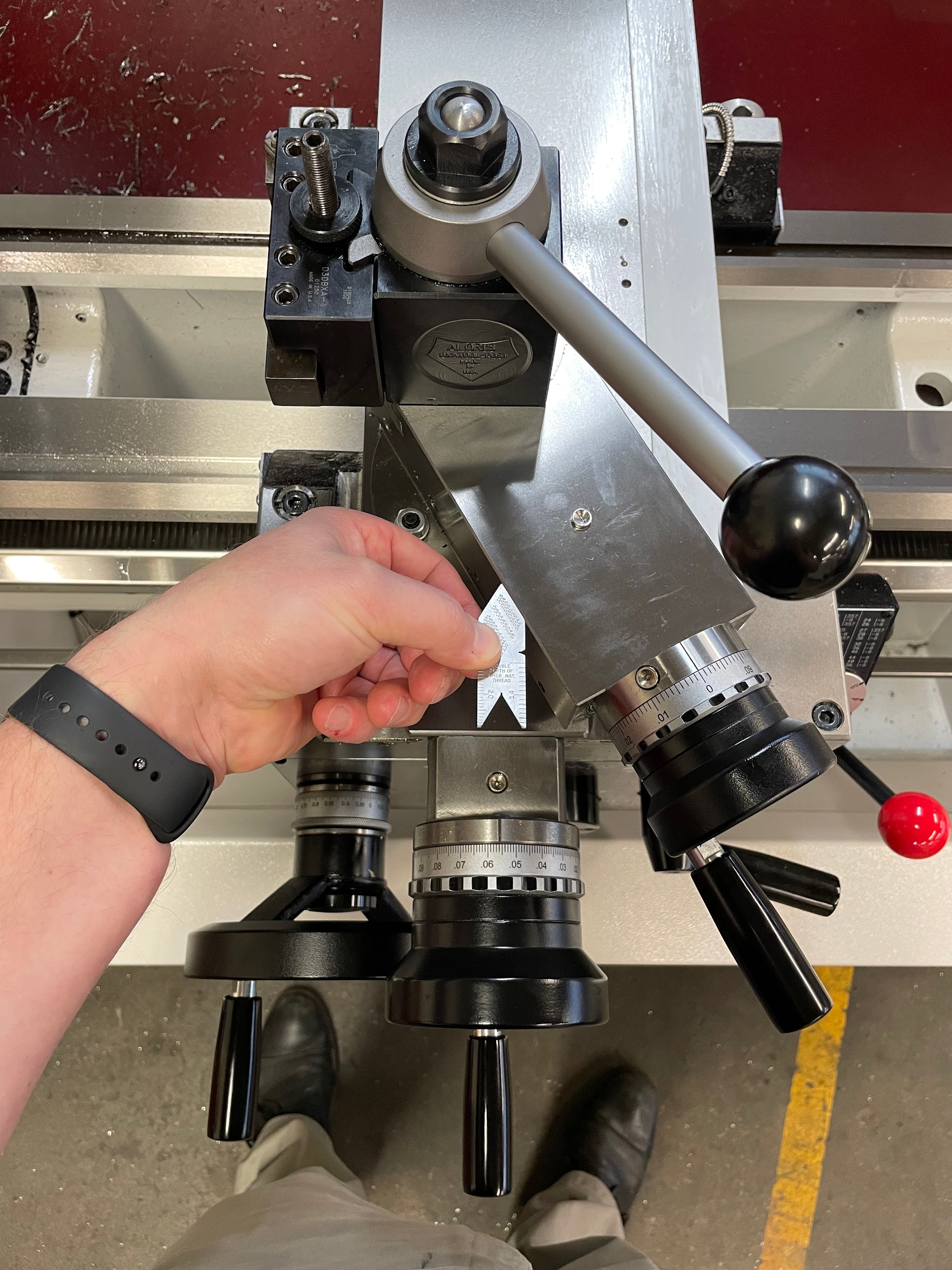
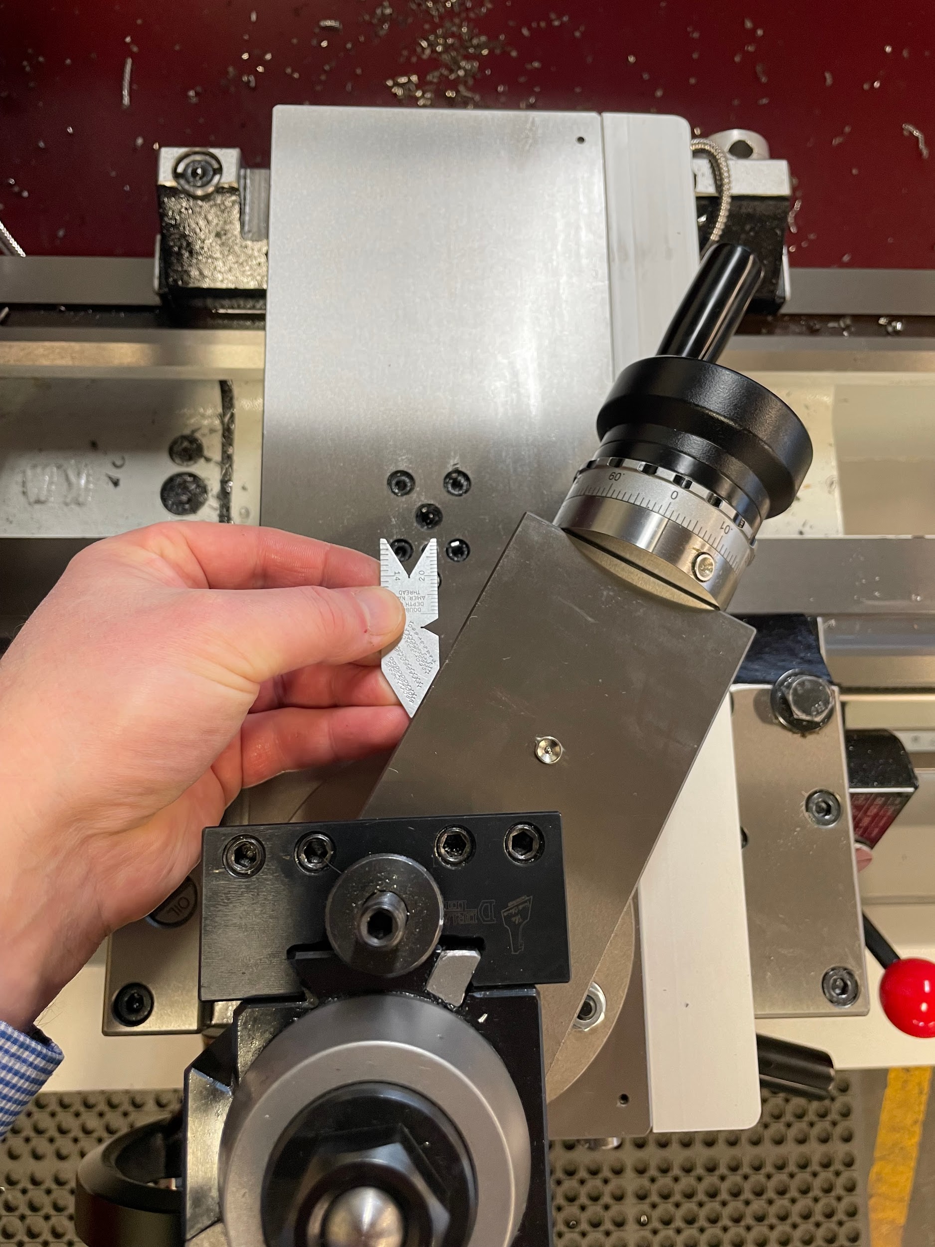
- Checking the compound rest angle with a center gage: After adjusting the compound rest to the correct angle, I like to use the 60 degree pointed end of the center gage to make sure I have adjusted correctly. To check using this method, put the right-side angle of the center gage against the left side of the compound rest and inspect the direction the center gage is pointing. If you have the compound rest set correctly, the center gage will be pointing within 1 degree of perpendicular to the axis of the work. The most common error when setting the compound is setting it to the 29 degree graduation. This method of checking will quickly expose the most common compound setup errors.
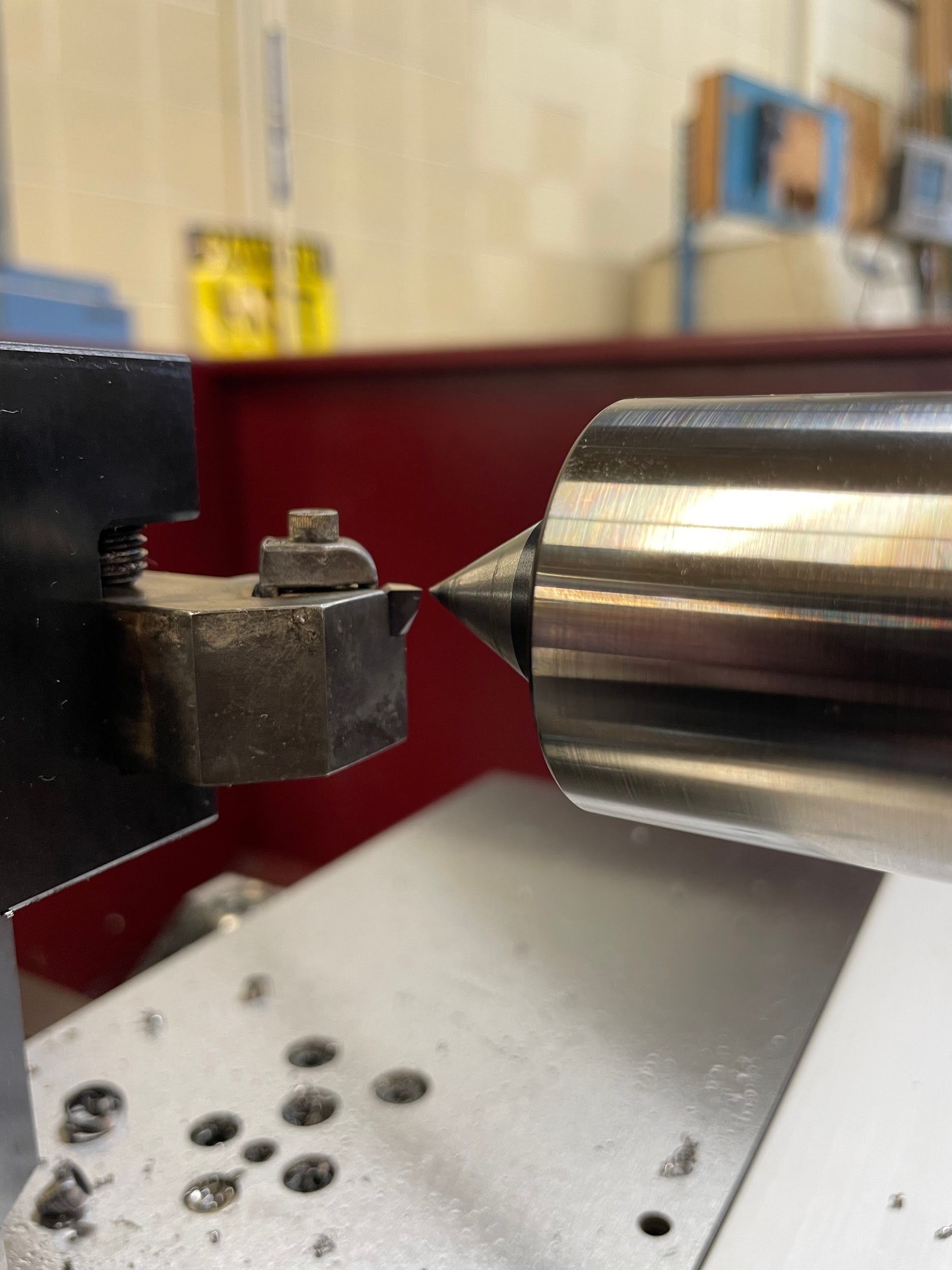
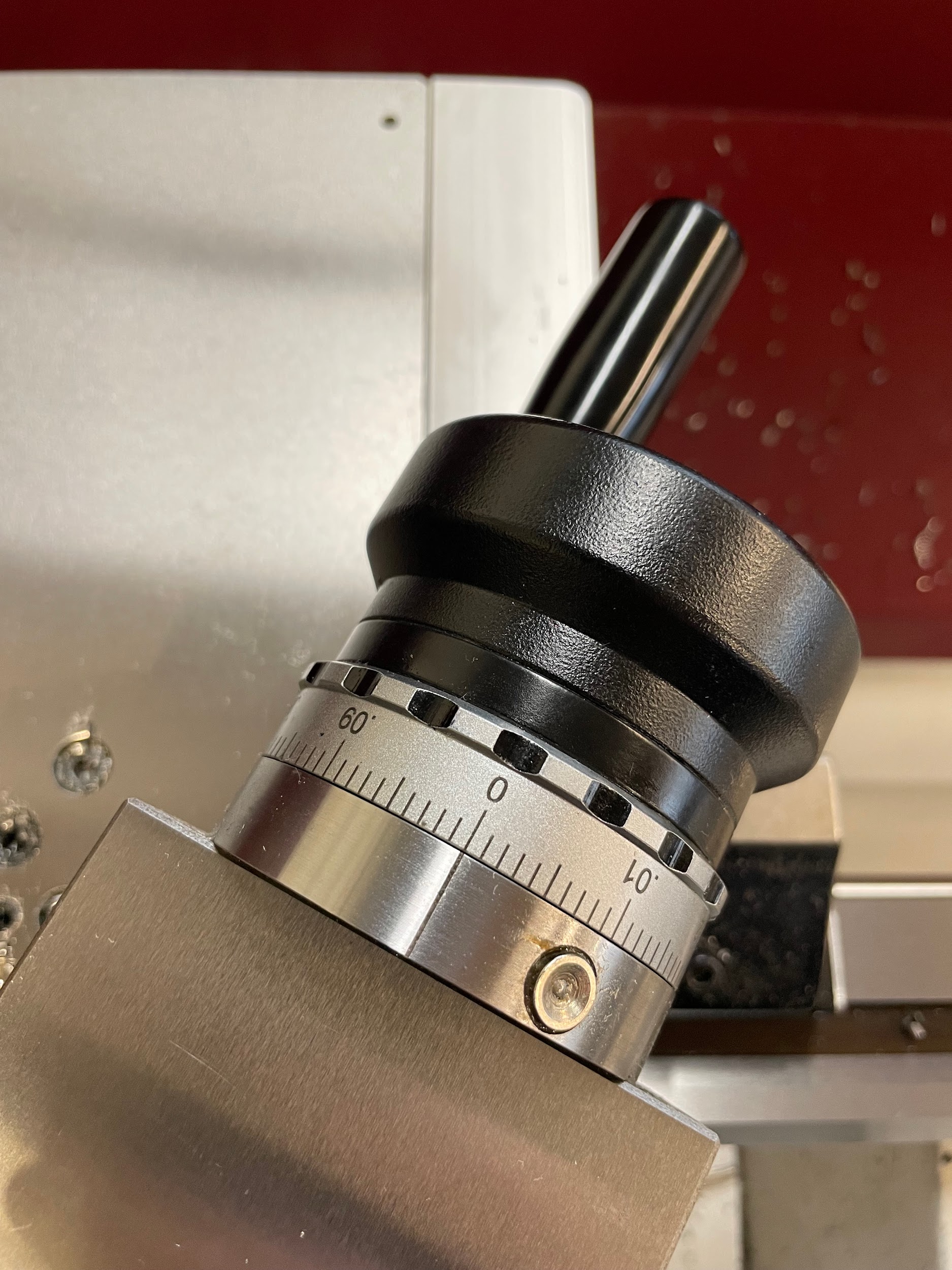
Video 10.103. A machinist accurately rotates the spindle one time by hand. The position of the jaws help to gage one full rotation. / Video Credit: Micky R. Jennings, courtesy of Wenatchee Valley College, CC BY 4.0 
Video 10.103. A machinist accurately rotates the spindle one time by hand. The position of the jaws help to gage one full rotation. / Video Credit: Micky R. Jennings, courtesy of Wenatchee Valley College, CC BY 4.0; video available online at https://www.youtube.com/shorts/hE2FmGfMczU or by scanning this QR code. - Verifying TPI before threading: After selecting the TPI needed for threading, I like to keep the lathe off and check that I have it in the correct gear. To do this, I simply engage the half nut lever, rotate the chuck so all the backlash is out of the system, set a zero position for the carriage, and turn the chuck one full rotation to see how far the carriage has moved. If the machine is set for the correct TPI, the movement of the lathe should be equal to the pitch of the desired thread.
- Using calipers to check TPI: When I am checking that my machined threads are the correct TPI, I prefer using my calipers instead of thread pitch gages. You can do this in a couple different ways. The first is to set your calipers to 1″, put the jaws in one of the threads, and count the number of additional threads until you reach the next jaw. A second method that I use is to calculate the pitch of the thread and then set my calipers to that, hold it up to the threads, and see if it matches with one complete thread rotation. This method works well if you have less than 1″ of thread. A combination of measuring TPI and the major diameter with calipers can be used to distinguish metric threads from inch unified threads.
- Tricks for measuring with thread wires: I don’t have three hands, and neither do you. When I am measuring using thread wires, I have a couple little tricks that help me. First, get a couple quality rubber bands and keep them in the thread wire pack. You will want to wrap one of the rubber bands around the two bottom wires so they are held in place underneath your thread. Second, balance the last wire in the top groove. Now you have two hands to carefully bring the movable anvil of the micrometer onto the top wire, keeping it from falling, and take the measurement.
Attributions
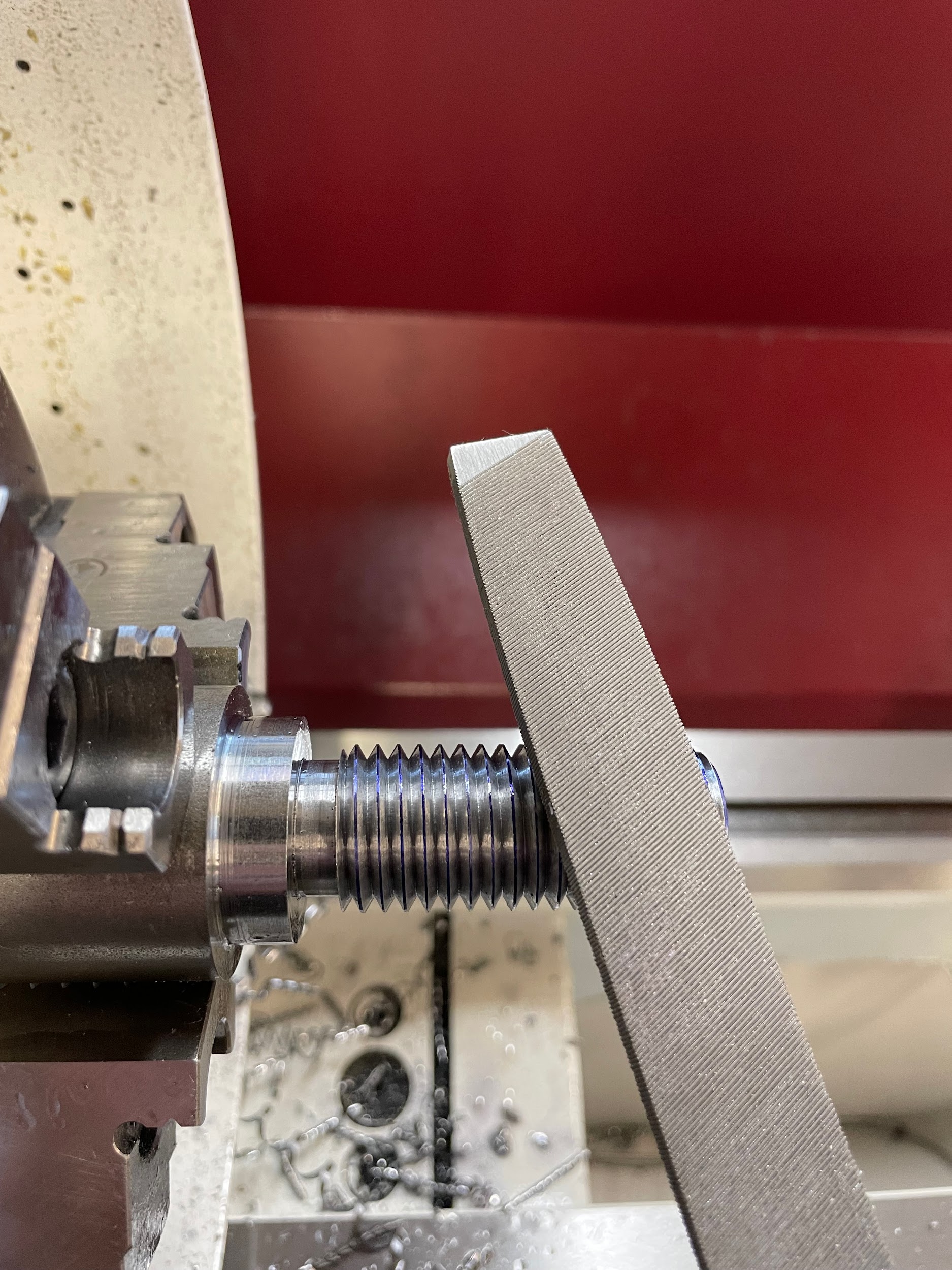
- Figure 10.172: Finished thread by Micky R. Jennings, courtesy of Wenatchee Valley College, for WA Open ProfTech, © SBCTC, CC BY 4.0
- Figure 10.173: Thumb screw by Micky R. Jennings, courtesy of Wenatchee Valley College, for WA Open ProfTech, © SBCTC, CC BY 4.0
- Figure 10.174: Tool height by Micky R. Jennings, courtesy of Wenatchee Valley College, for WA Open ProfTech, © SBCTC, CC BY 4.0
- Figure 10.175: Setting the compound rest angle by Micky R. Jennings, courtesy of Wenatchee Valley College, for WA Open ProfTech, © SBCTC, CC BY 4.0
- Figure 10.176: Checking the tool post angle by Micky R. Jennings, courtesy of Wenatchee Valley College, for WA Open ProfTech, © SBCTC, CC BY 4.0
- Figure 10.177: Threading chart by Micky R. Jennings, courtesy of Wenatchee Valley College, for WA Open ProfTech, © SBCTC, CC BY 4.0
- Figure 10.178: Quick change gearbox selection knobs by Micky R. Jennings, courtesy of Wenatchee Valley College, for WA Open ProfTech, © SBCTC, CC BY 4.0
- Figure 10.179: Applying layout dye by Micky R. Jennings, courtesy of Wenatchee Valley College, for WA Open ProfTech, © SBCTC, CC BY 4.0
- Figure 10.180: Cross slide handwheel in set position by Micky R. Jennings, courtesy of Wenatchee Valley College, for WA Open ProfTech, © SBCTC, CC BY 4.0
- Video 10.87: Micky R. Jennings, courtesy of Wenatchee Valley College, for WA Open ProfTech, © SBCTC, CC BY 4.0
- Figure 10.181: Touching off the tool by Micky R. Jennings, courtesy of Wenatchee Valley College, for WA Open ProfTech, © SBCTC, CC BY 4.0
- Video 10.88: Micky R. Jennings, courtesy of Wenatchee Valley College, for WA Open ProfTech, © SBCTC, CC BY 4.0
- Figure 10.182: Zeroing the compound rest by Micky R. Jennings, courtesy of Wenatchee Valley College, for WA Open ProfTech, © SBCTC, CC BY 4.0
- Video 10.89: Micky R. Jennings, courtesy of Wenatchee Valley College, for WA Open ProfTech, © SBCTC, CC BY 4.0
- Figure 10.183: Threading chart by Micky R. Jennings, courtesy of Wenatchee Valley College, for WA Open ProfTech, © SBCTC, CC BY 4.0
- Figure 10.184: Engaging the half nut lever by Micky R. Jennings, courtesy of Wenatchee Valley College, for WA Open ProfTech, © SBCTC, CC BY 4.0
- Video 10.90: Micky R. Jennings, courtesy of Wenatchee Valley College, for WA Open ProfTech, © SBCTC, CC BY 4.0
- Video 10.91: Micky R. Jennings, courtesy of Wenatchee Valley College, for WA Open ProfTech, © SBCTC, CC BY 4.0
- Figure 10.185: Checking pitch by Micky R. Jennings, courtesy of Wenatchee Valley College, for WA Open ProfTech, © SBCTC, CC BY 4.0
- Video 10.92: Micky R. Jennings, courtesy of Wenatchee Valley College, for WA Open ProfTech, © SBCTC, CC BY 4.0
- Video 10.93: Micky R. Jennings, courtesy of Wenatchee Valley College, for WA Open ProfTech, © SBCTC, CC BY 4.0
- Video 10.94: Micky R. Jennings, courtesy of Wenatchee Valley College, for WA Open ProfTech, © SBCTC, CC BY 4.0
- Figure 10.186: Cleaning the threads by Micky R. Jennings, courtesy of Wenatchee Valley College, for WA Open ProfTech, © SBCTC, CC BY 4.0
- Figure 10.187: Measuring a thread by Micky R. Jennings, courtesy of Wenatchee Valley College, for WA Open ProfTech, © SBCTC, CC BY 4.0
- Figure 10.188: Measuring a thread 2 by Micky R. Jennings, courtesy of Wenatchee Valley College, for WA Open ProfTech, © SBCTC, CC BY 4.0
- Figure 10.189: Adjusting the cross slide by Micky R. Jennings, courtesy of Wenatchee Valley College, for WA Open ProfTech, © SBCTC, CC BY 4.0
- Video 10.95: Micky R. Jennings, courtesy of Wenatchee Valley College, for WA Open ProfTech, © SBCTC, CC BY 4.0
- Figure 10.190: Measuring a thread 3 by Micky R. Jennings, courtesy of Wenatchee Valley College, for WA Open ProfTech, © SBCTC, CC BY 4.0
- Figure 10.191: Deburring a thread by Micky R. Jennings, courtesy of Wenatchee Valley College, for WA Open ProfTech, © SBCTC, CC BY 4.0
- Video 10.96: Micky R. Jennings, courtesy of Wenatchee Valley College, for WA Open ProfTech, © SBCTC, CC BY 4.0
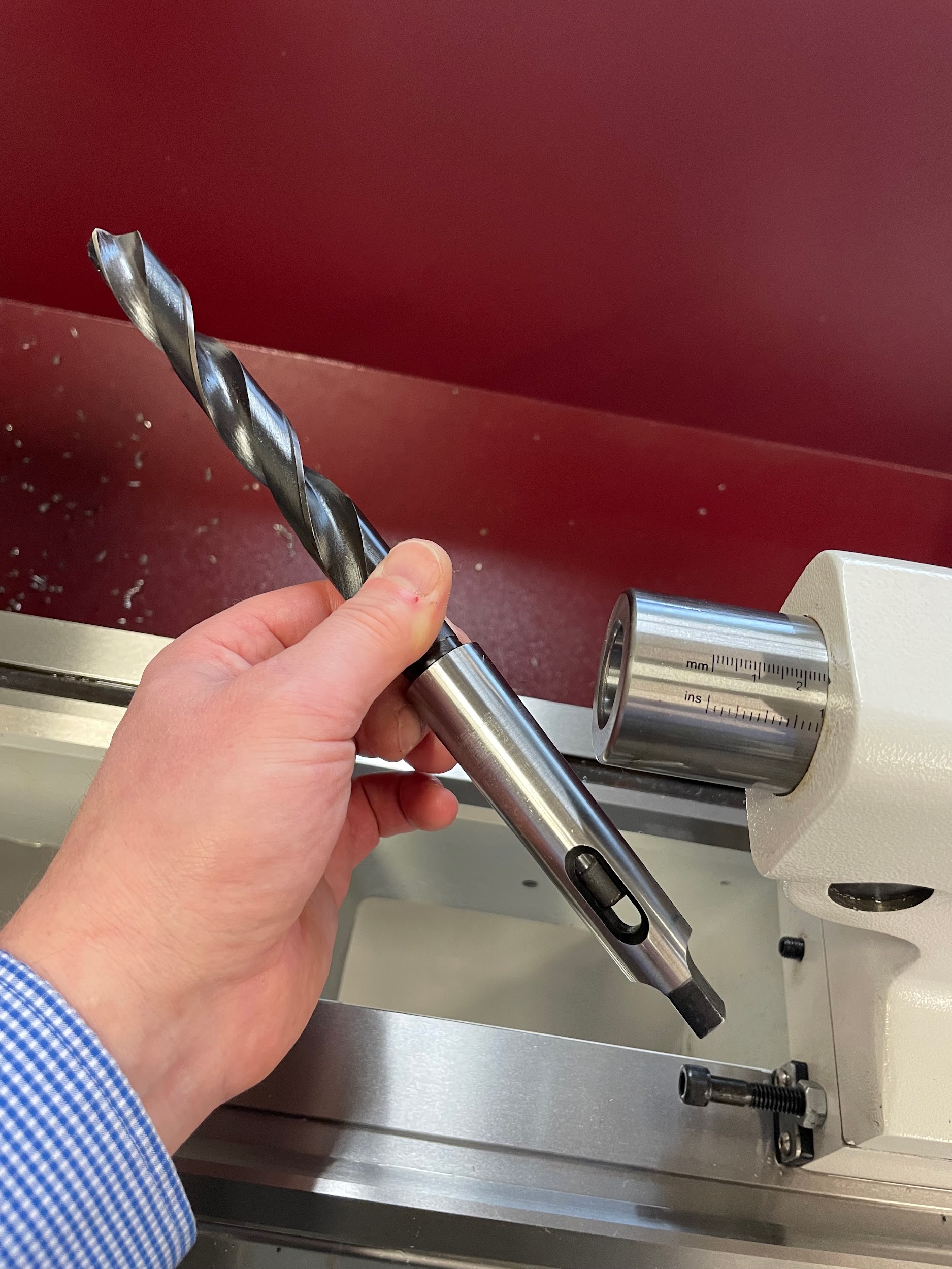
- Figure 10.192: Installing a drill by Micky R. Jennings, courtesy of Wenatchee Valley College, for WA Open ProfTech, © SBCTC, CC BY 4.0
- Video 10.97: Micky R. Jennings, courtesy of Wenatchee Valley College, for WA Open ProfTech, © SBCTC, CC BY 4.0
- Video 10.98: Micky R. Jennings, courtesy of Wenatchee Valley College, for WA Open ProfTech, © SBCTC, CC BY 4.0
- Figure 10.193: Checking the tool post for alignment by Micky R. Jennings, courtesy of Wenatchee Valley College, for WA Open ProfTech, © SBCTC, CC BY 4.0
- Figure 10.194: Squared tool post by Micky R. Jennings, courtesy of Wenatchee Valley College, for WA Open ProfTech, © SBCTC, CC BY 4.0
- Figure 10.195: Checking the threading bar by Micky R. Jennings, courtesy of Wenatchee Valley College, for WA Open ProfTech, © SBCTC, CC BY 4.0
- Figure 10.196: Tool height by Micky R. Jennings, courtesy of Wenatchee Valley College, for WA Open ProfTech, © SBCTC, CC BY 4.0
- Figure 10.197: Checking the threading bar 2 by Micky R. Jennings, courtesy of Wenatchee Valley College, for WA Open ProfTech, © SBCTC, CC BY 4.0
- Figure 10.198: Checking the tool post angle by Micky R. Jennings, courtesy of Wenatchee Valley College, for WA Open ProfTech, © SBCTC, CC BY 4.0
- Figure 10.199: Zeroing the cross slide 2 by Micky R. Jennings, courtesy of Wenatchee Valley College, for WA Open ProfTech, © SBCTC, CC BY 4.0
- Figure 10.200: Touch off the tool by Micky R. Jennings, courtesy of Wenatchee Valley College, for WA Open ProfTech, © SBCTC, CC BY 4.0
- Figure 10.201: Zeroing the compound rest 2 by Micky R. Jennings, courtesy of Wenatchee Valley College, for WA Open ProfTech, © SBCTC, CC BY 4.0
- Video 10.99: Micky R. Jennings, courtesy of Wenatchee Valley College, for WA Open ProfTech, © SBCTC, CC BY 4.0
- Video 10.100: Micky R. Jennings, courtesy of Wenatchee Valley College, for WA Open ProfTech, © SBCTC, CC BY 4.0
- Figure 10.202: Threaded ring gages by Micky R. Jennings, courtesy of Wenatchee Valley College, for WA Open ProfTech, © SBCTC, CC BY 4.0
- Figure 10.203: Threaded plug gage by Micky R. Jennings, courtesy of Wenatchee Valley College, for WA Open ProfTech, © SBCTC, CC BY 4.0
- Video 10.101: Micky R. Jennings, courtesy of Wenatchee Valley College, for WA Open ProfTech, © SBCTC, CC BY 4.0
- Figure 10.204: Go gage checking by Micky R. Jennings, courtesy of Wenatchee Valley College, for WA Open ProfTech, © SBCTC, CC BY 4.0
- Video 10.102: Micky R. Jennings, courtesy of Wenatchee Valley College, for WA Open ProfTech, © SBCTC, CC BY 4.0
- Figure 10.205: No-go gage checking by Micky R. Jennings, courtesy of Wenatchee Valley College, for WA Open ProfTech, © SBCTC, CC BY 4.0
- Figure 10.206: Thread micrometer by Micky R. Jennings, courtesy of Wenatchee Valley College, for WA Open ProfTech, © SBCTC, CC BY 4.0
- Figure 10.207: Thread micrometer calibration check by Micky R. Jennings, courtesy of Wenatchee Valley College, for WA Open ProfTech, © SBCTC, CC BY 4.0
- Figure 10.208: Measuring with a thread micrometer. by Micky R. Jennings, courtesy of Wenatchee Valley College, for WA Open ProfTech, © SBCTC, CC BY 4.0
- Figure 10.209: Thread wires by Micky R. Jennings, courtesy of Wenatchee Valley College, for WA Open ProfTech, © SBCTC, CC BY 4.0
- Figure 10.210: Three thread wires by Micky R. Jennings, courtesy of Wenatchee Valley College, for WA Open ProfTech, © SBCTC, CC BY 4.0
- Figure 10.211: Bottom two thread wires by Micky R. Jennings, courtesy of Wenatchee Valley College, for WA Open ProfTech, © SBCTC, CC BY 4.0
- Figure 10.212: Top thread wire by Micky R. Jennings, courtesy of Wenatchee Valley College, for WA Open ProfTech, © SBCTC, CC BY 4.0
- Figure 10.213: Measuring over thread wires by Micky R. Jennings, courtesy of Wenatchee Valley College, for WA Open ProfTech, © SBCTC, CC BY 4.0
- Figure 10.214: Checking the compound rest angle for threading by Micky R. Jennings, courtesy of Wenatchee Valley College, for WA Open ProfTech, © SBCTC, CC BY 4.0
- Figure 10.215: Checking the compound rest angle for threading by Micky R. Jennings, courtesy of Wenatchee Valley College, for WA Open ProfTech, © SBCTC, CC BY 4.0
- Video 10.103: Micky R. Jennings, courtesy of Wenatchee Valley College, for WA Open ProfTech, © SBCTC, CC BY 4.0
The process of cutting threads on the lathe.
The general size that identifies a thread.
The actual size of the largest diameter of a thread.
The actual size of the smallest diameter of a thread.
The theoretical diameter where the widths of the threads and the grooves are equal.
TPI, The number of threads in one inch of length measured along the thread.
the distance from one tooth to the next. exspressed as 1/TPI.
The amount a thread moves an object axially during a single rotation.
The top flat surface of a thread.
The surface at the bottom of the groove of a thread.
The load bearing angled surfaces of a thread between the root and the crest.
A fixed gage used to check external thread size. Generally used in a set, one go, one no-go.
A fixed gage used to check internal thread size. Generally used in a set, one go, one no-go.
Also called a Pitch Micrometer, this is a special purpose micrometer used to measure the pitch diameter of threads.
