10.20 Knurling
Micky R. Jennings
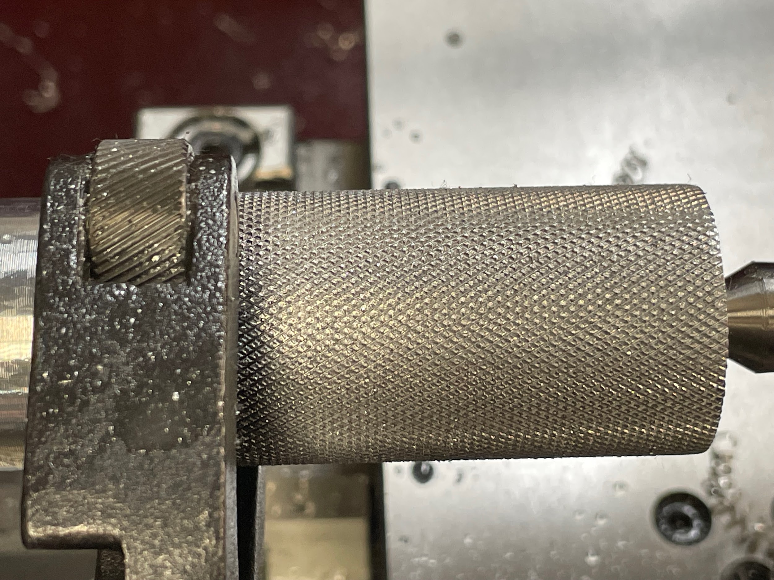
Knurling is the process of impressing diamond, straight or other patterns into the workpiece with a tool known as a knurler. The knurl is created when the wheels of the knurling tool are pressed into the work with enough pressure to displace the work material creating a serration with raised edges. The knurler makes these serrations and raised edges over and over as the part is rotated and the knurling wheels track along the surface of the part. This repeated impression gradually displaces more material with each rotation. As the knurling tool feeds along the work, properly tracking wheels will create the desired pattern. Testing a planned knurl on a piece of scrap to perfect the technique is good practice before attempting it on a valuable piece of material.
Step by step process for knurling with a scissor knurler:
- Prepare the work by turning a diameter slightly smaller than the desired size of the knurl. Often between .01 and .03 smaller, depending on the size of the knurls desired.
- Layout the desired length to be knurled with an odd leg caliper.
- Select the correct knurling wheels for the pattern indicated on the print. (This example is for medium knurls.)
- Align the tool post with the work.
- Mount the knurling tool squarely in a tool holder.
- Install the holder securely on the tool post.
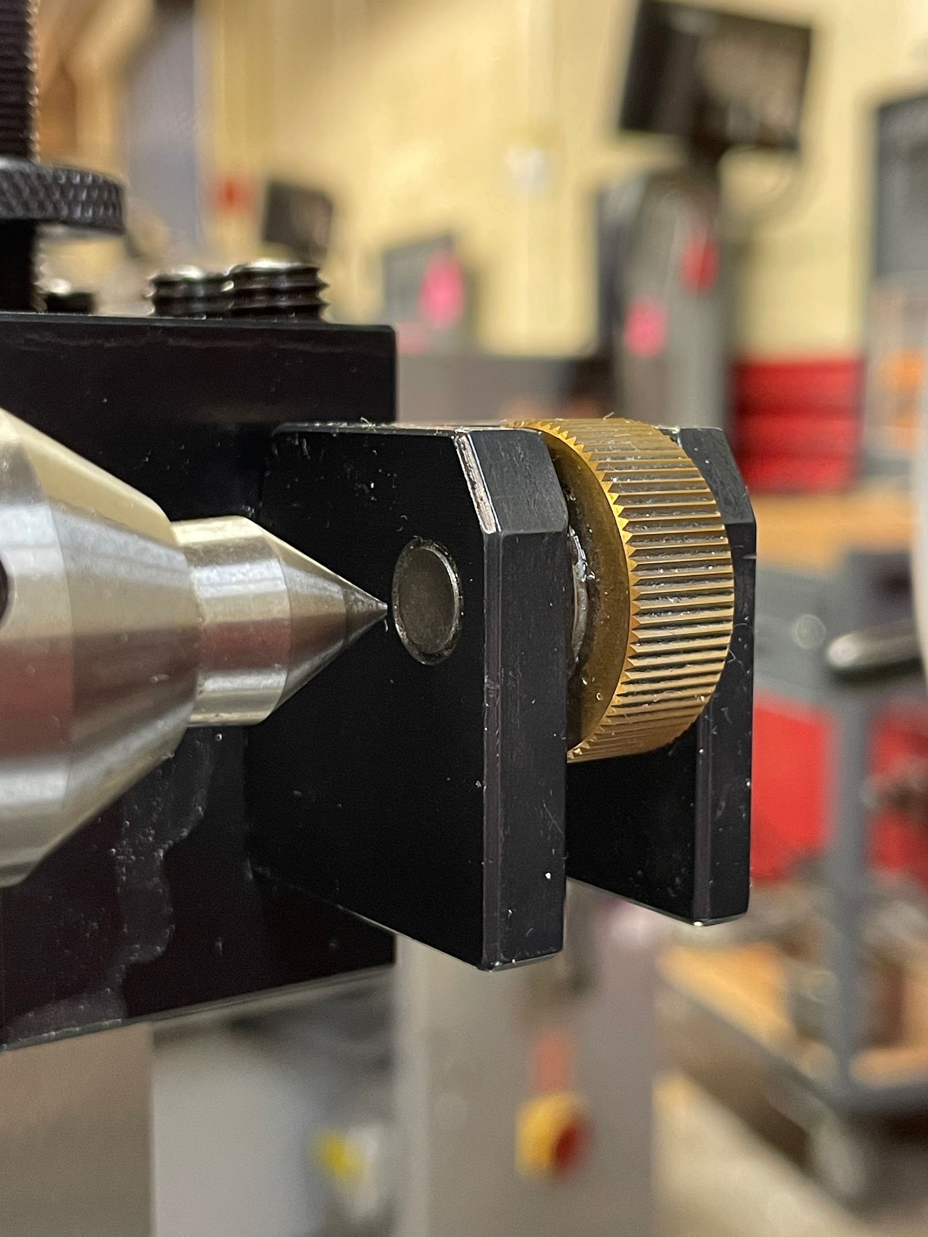
- Set the tool height by referencing the pivot point of the tool with the tailstock center.
- Open the tool by backing off the adjustment nut so the wheels will clear the OD of the work.
- Position the carriage so that the wheels line up half on and half off the end of the part.
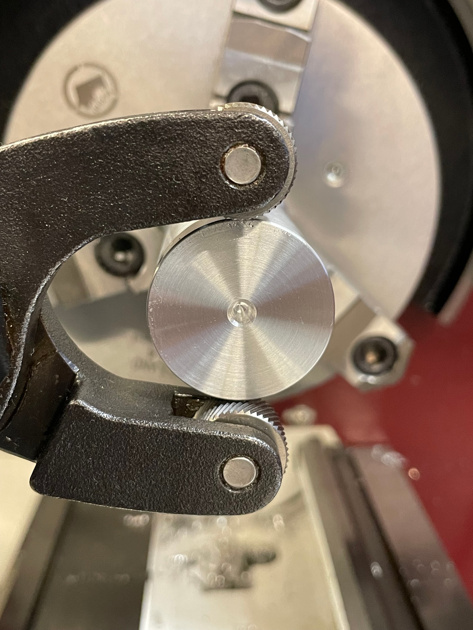
- Position the cross slide so the wheels are directly above and below the part, at 12 and 6 o’clock.
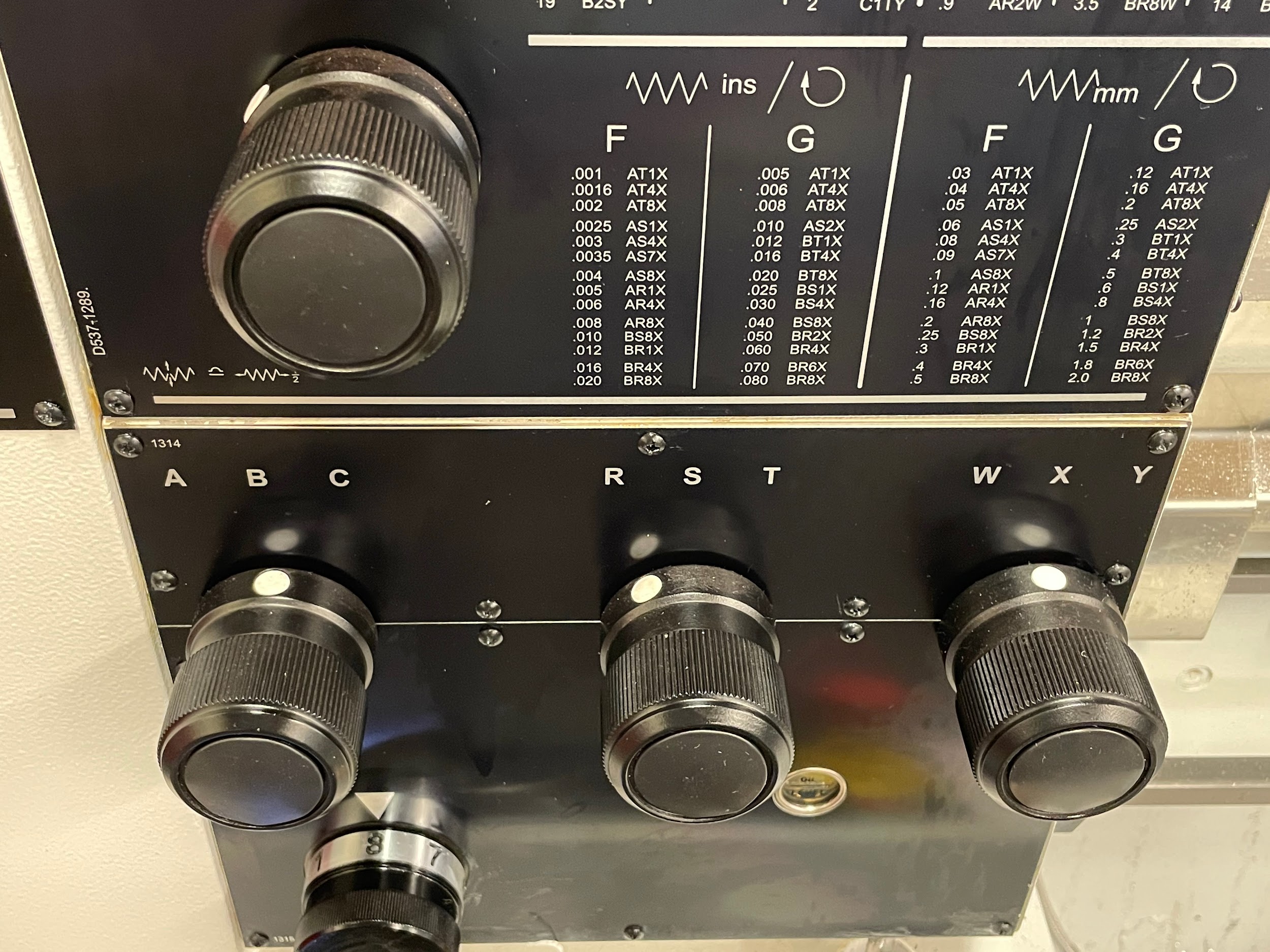
- Calculate and set the spindle speed for the knurling operation. Generally, somewhere between 50 and 500 RPMs.
- Calculate and set the desired feed rate. Knurling can be performed at a fairly fast feed rate. If the tool is allowed to impress too many times on a particular stretch of material, it will raise the material to the point where it will over form and start flaking away from the part. This generally occurs somewhere between .01 and .03 IPR.
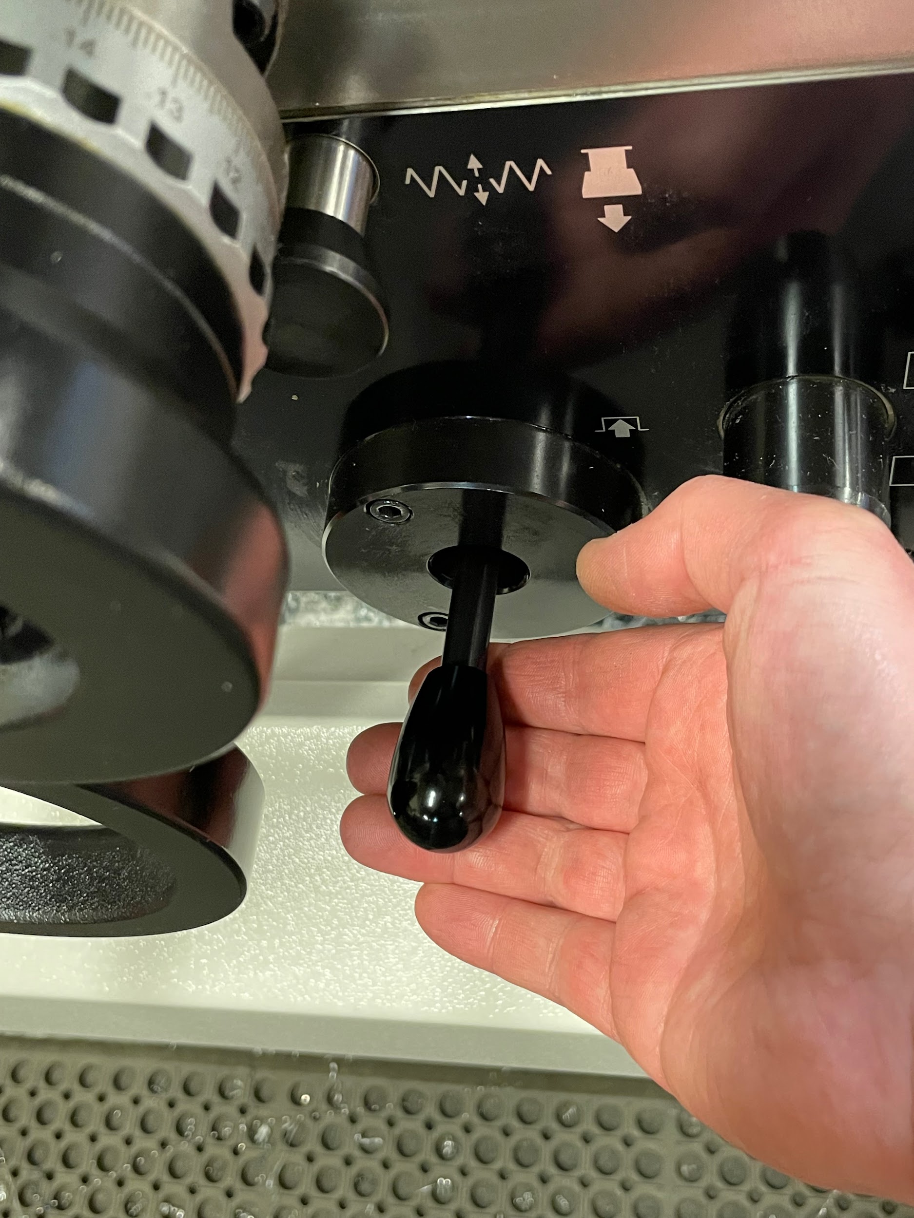
- Engage the carriage power feed lever. Doing this will ensure that when the spindle is turned on, the carriage will immediately start moving. One of the things that will adversely affect a knurl is dwelling in one spot. Doing so will form more knurls in the dwelling area, causing an undesirable ring effect.
- Engage the tailstock into the end of the part if possible, for extra support.
- Tighten the adjustment nut by hand so the knurling wheels are securely in contact with the OD of the work.
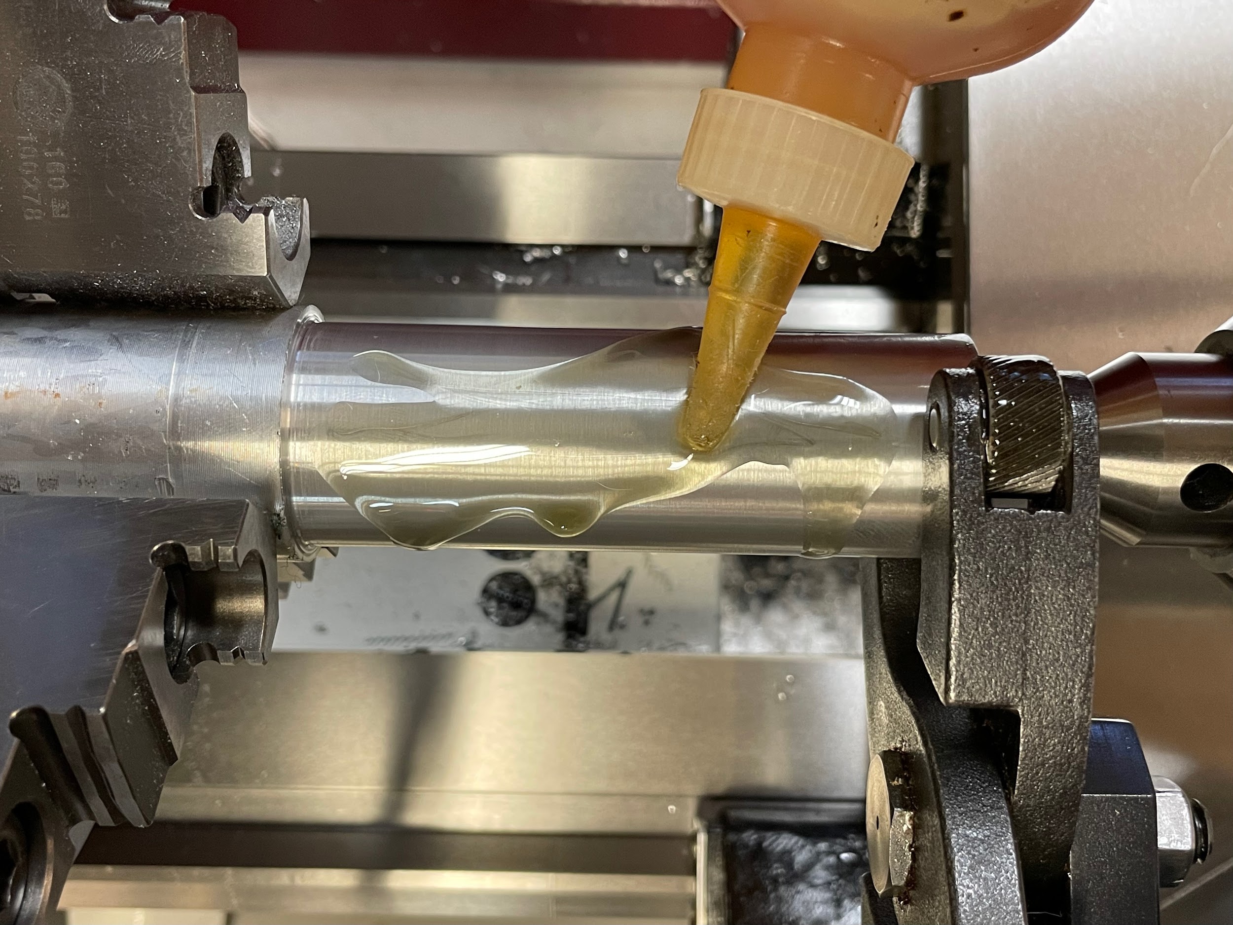
- Liberally lubricate the knurling wheels and work.
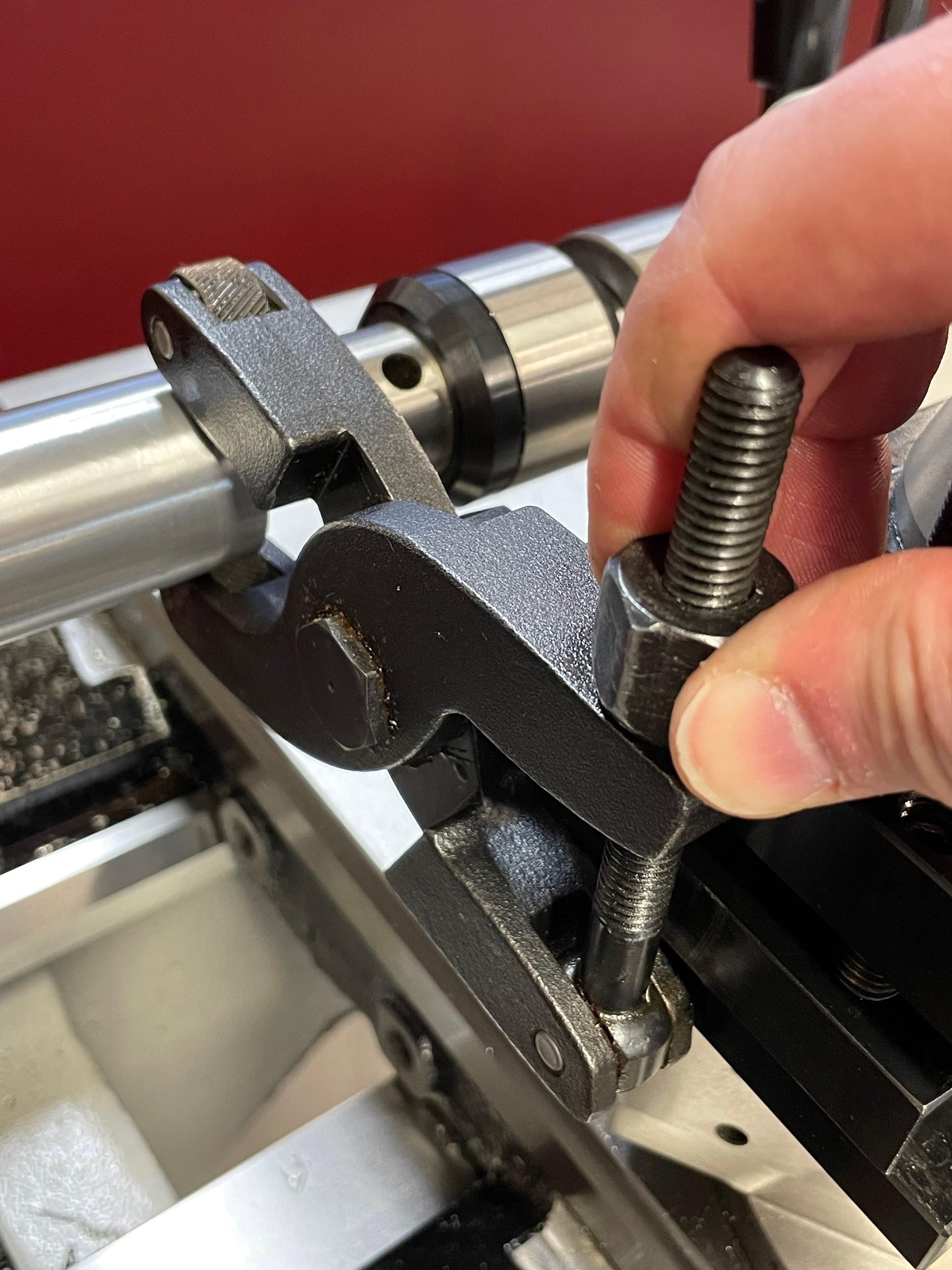
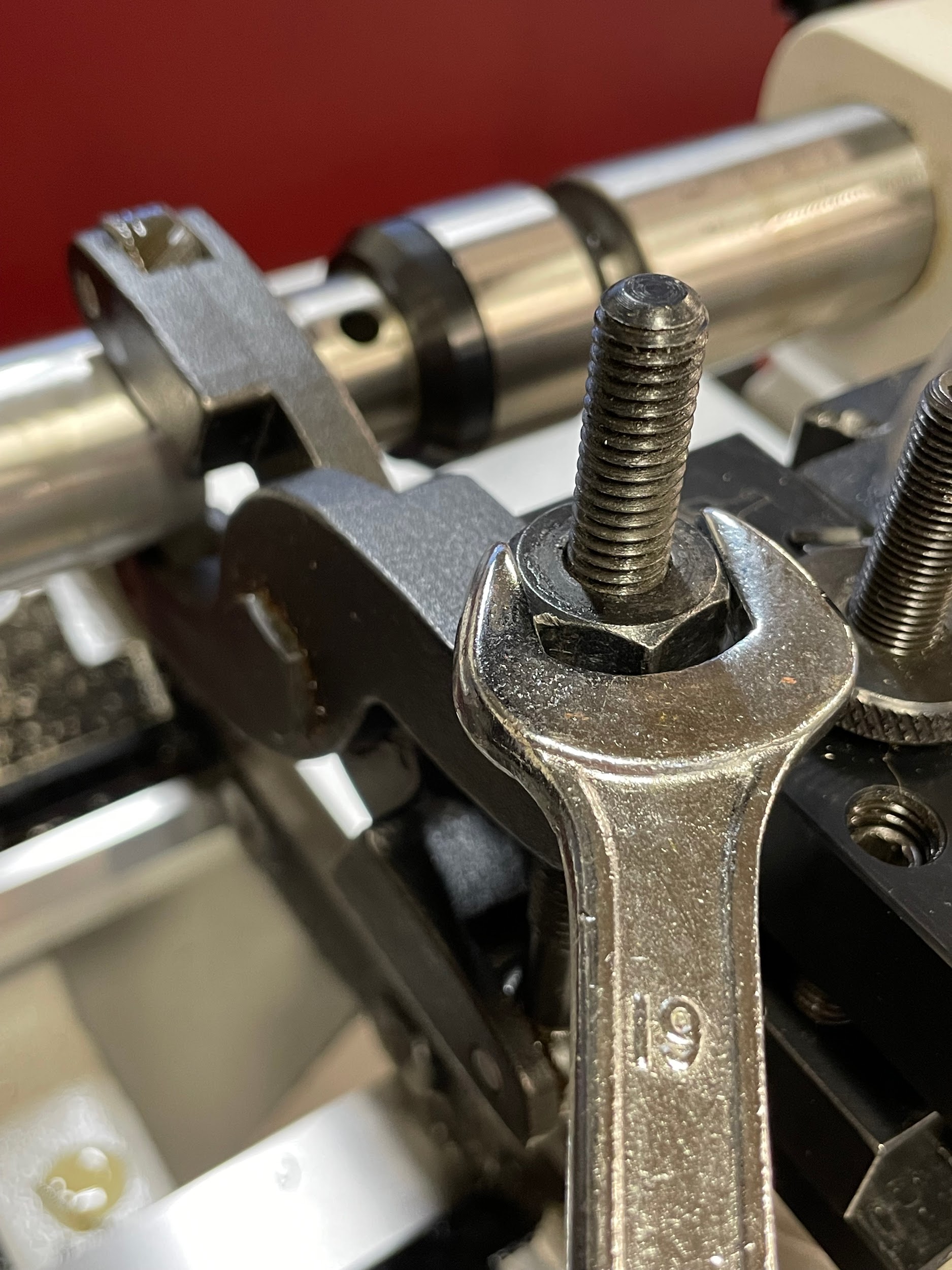
- Tighten the adjustment nut with a wrench to set the knurling pressure. This is subjective to the type and size of the knurl as well as the material being knurled. A good starting place would be 1/6th to 3/6th of a turn.
- Turn the spindle on and allow the spindle to rotate about 5 times before shutting it off again.
- Using compressed air, blow the oil out of the knurl and inspect it for correct depth and double cutting. Double cutting is when one or both of the knurling wheels incorrectly track the part and make twice as many serrations as they are supposed to. At this point, if the knurl isn’t correct, there may be an opportunity to adjust or fix the part. Double cutting is less likely to happen on freshly turned concentric diameters by setting the scissor tension before starting the spindle and by using cutting oil.
- If the knurl is forming correctly, lubricate the wheels as well as the rest of the part and turn the spindle back on.
- Watch the knurling wheels closely during the forming process. Apply cutting oil to the top wheel with a squeeze bottle while the part is in motion if it appears to get dry. Do not use a brush to apply oil during knurling operations. Brushes can get caught in the knurling wheels, damaging the part or tool.
- Turn the spindle off once the knurling tool reaches the layout line.
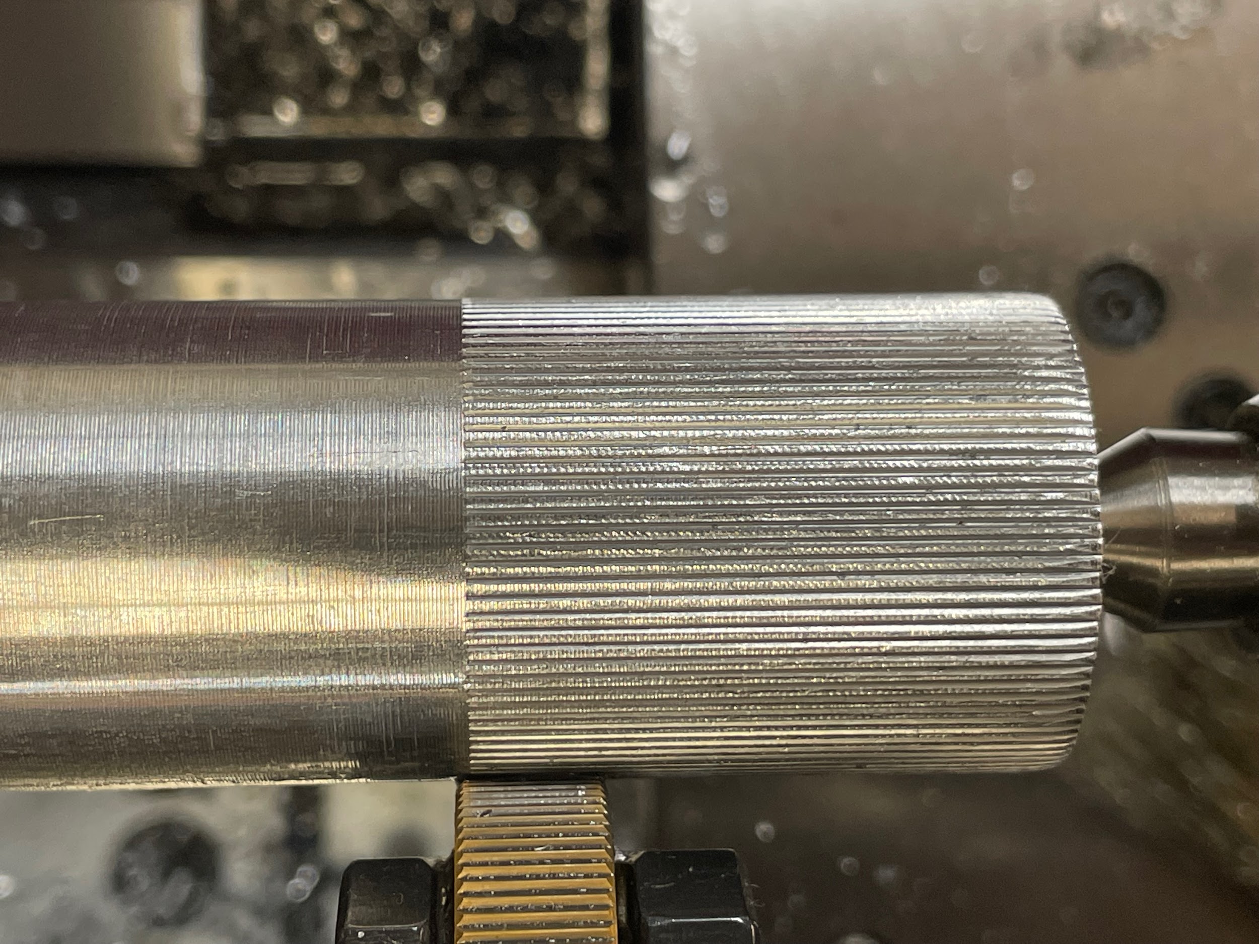
- Inspect the knurls.
- When the spindle stops, disengage the power feed. Disengaging the power feed anywhere along the length of the formed material while the spindle is rotating will cause dwell rings.
- Loosen the adjustment.
- Back the knurling tool away from the material with the cross slide.
Author’s Tip
On occasion, I might think the depth of my knurl is good when I first look at it, but once it gets to the end and I turn off the spindle to have a good look at it, I realize it is shallower than what I want. In an instance like this, I might decide to go back over the existing knurl by switching the direction of the power feed at the headstock. Switching the feed from into the chuck to away from the chuck without altering the tool or its engagement will allow the tool to feed back over the existing knurl and impress it a little bit more once the spindle is restarted. Sometimes taking a calculated risk like this, or possibly ending up with an over formed knurl, is better than having a knurl that is too shallow.
Step 4: Align the tool post with the work.
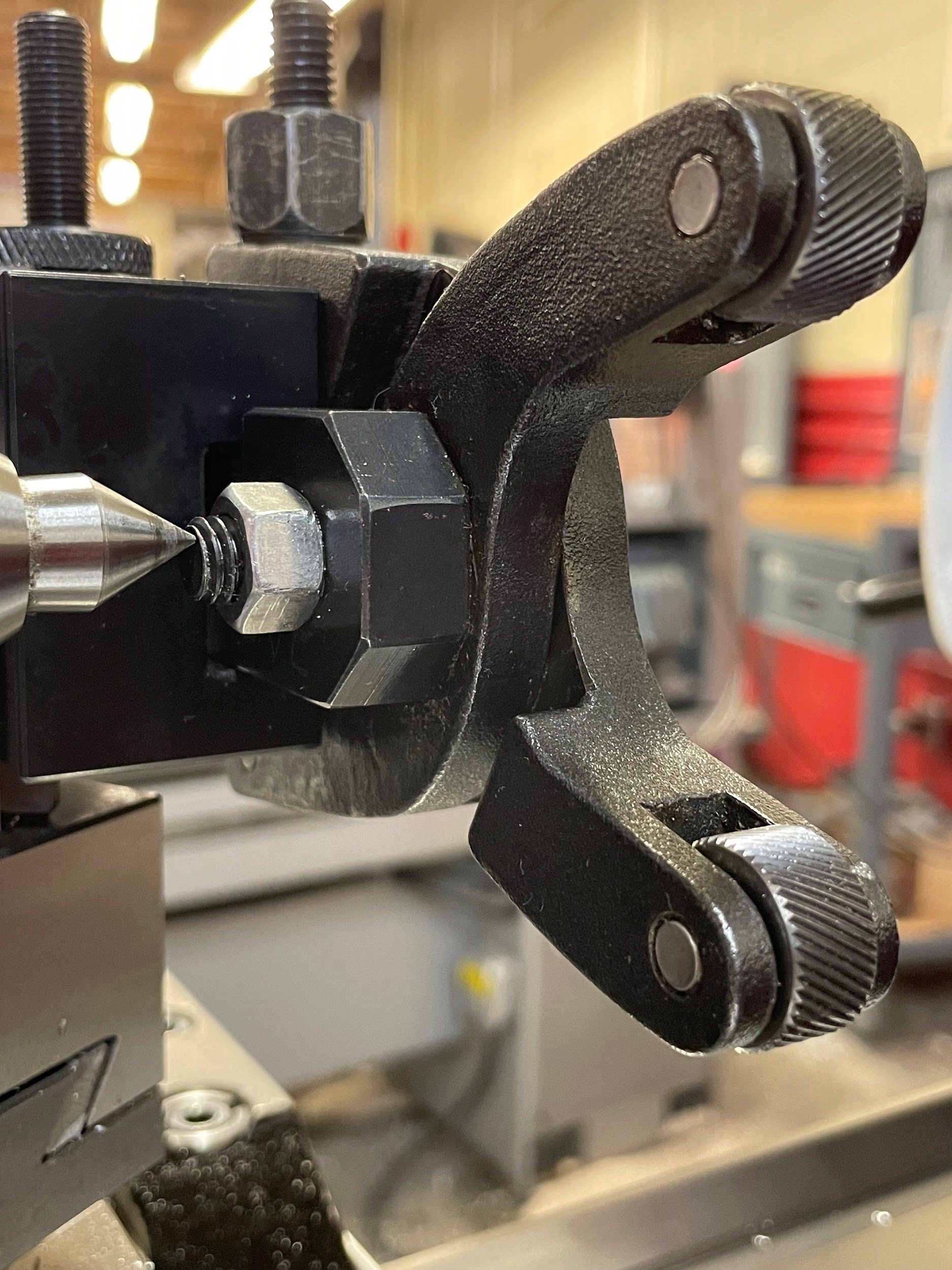
Step 7: Set the tool height by referencing the pivot point of the tool with the tailstock center.
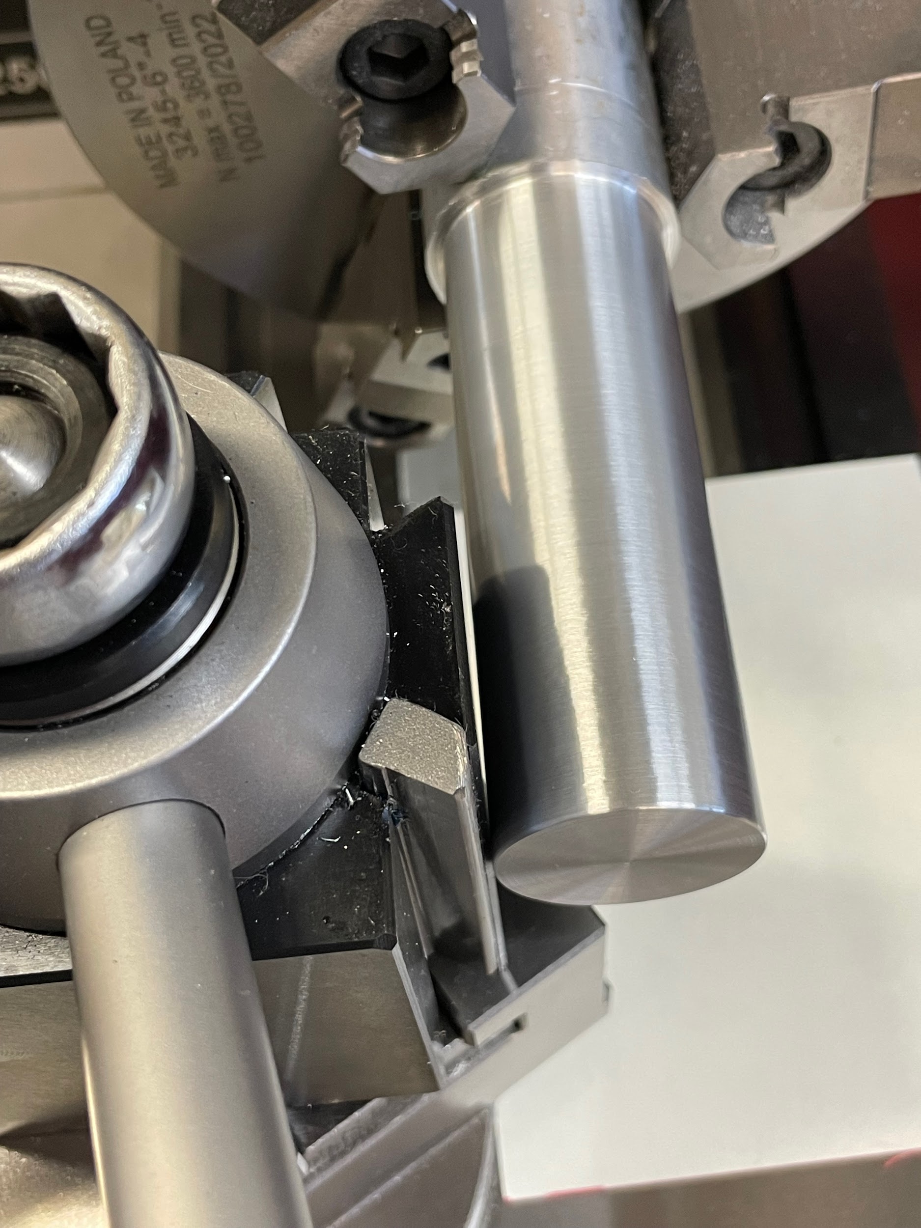
Step 9: Position the carriage so that the wheels line up half on, and half off the end of the part.
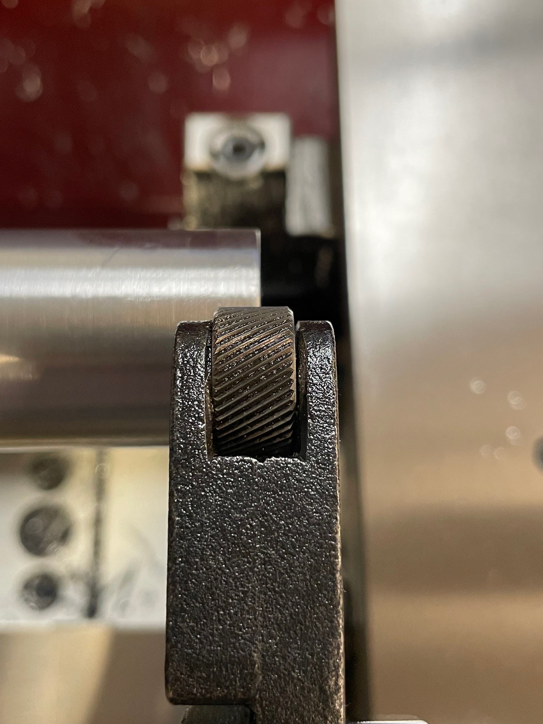
Step 10: Position the cross slide so the wheels are directly above and below the part, at 12 and 6 o’clock.
Step 12: Calculate and set the desired feed rate. Knurling can be performed at a fairly fast feed rate. If the tool is allowed to impress too many times on a particular stretch of material, it will raise the material to the point where it will over form and start flaking away from the part. This point is generally somewhere between .01 and .03 IPR.
Step 13: Engage the carriage power feed lever. Doing this will ensure that when the spindle is turned on, the carriage will immediately start moving. One of the things that will adversely affect a knurl is dwelling in one spot. Doing so will form the knurls more in the dwelling area, causing an undesirable ring effect.
Step 15: Tighten the adjustment nut by hand so the knurling wheels are securely in contact with the OD of the work.
Step 16: Liberally lubricate the knurling wheels and work.
Step 17: Tighten the adjustment nut with a wrench to set the knurling pressure. This is subjective to the type and size of the knurl as well as the material being knurled. A good starting place would be 1/6th to 3/6th of a turn.
Step 18: Turn the spindle on and allow the spindle to rotate about 5 times before shutting it off again.

Step 22: Turn the spindle off once the knurling tool reaches the layout line.

Step 23: Inspect the knurls.

Step by step process for knurling with a bump knurler:
- Prepare the work by turning a diameter slightly smaller than the desired size of the knurl. Often between .01 and .03 smaller, depending on the size of the knurls desired.
- Layout the desired length to be knurled with an odd leg caliper.
- Select the correct knurling wheels for the pattern indicated on the print. (This example is for a straight knurl.)
- Align the tool post with the work
- Mount the knurling tool squarely in a tool holder.
- Install the holder securely on the tool post.
- Set the tool height by referencing the midpoint of the tool with the tailstock center.
- Position the carriage so that the wheels line up half on and half off the end of the part.
- Calculate and set the spindle speed for the knurling operation. Generally, somewhere between 50 and 200 RPMs.
- Calculate and set the desired feed rate. Knurling can be performed at a fairly fast feed rate. If the tool is allowed to impress too many times on a particular stretch of material, it will raise the material to the point where it will over form and start flaking away from the part. This point is generally somewhere between .01 and .03 IPR.
- Engage the tailstock into the end of the part, if possible, for extra support.
- Gently touch the knurling wheels to the outside of the work and zero the cross slide.
- Back off the cross slide so the wheel/s are about 1/32″ away from the diameter of the work.
- Liberally lubricate the knurling wheels and the end of the work.
- Turn the spindle on.
- Quickly and forcefully engage the cross slide, pushing the knurling wheels into the work to set the knurling pressure. This is subjective to the type and size of knurl as well as the material being knurled. A good starting place is .02 to .05 on the cross slide. Allow the spindle to rotate about 5 times before shutting it off again.
- Using compressed air, blow the oil out of the knurl and inspect it for correct depth and double cutting. Double cutting is when one or both of the knurling wheels incorrectly track the part and make twice as many serrations as they are supposed to. At this point, if the knurl isn’t correct, there may be an opportunity to adjust or fix the part. Double cutting is less likely to happen on freshly turned concentric diameters, by engaging the part quickly to depth, and by using cutting oil.
- If the knurl is forming correctly, lubricate the wheels as well as the rest of the part.
- Engage the carriage power feed. Doing this will ensure that when the spindle is turned on, the carriage will immediately start moving. One of the things that will adversely affect a knurl is dwelling in one spot. Doing so will form the knurls more in the dwelling area, causing an undesirable ring effect.
- Turn the spindle back on.
- Watch the knurling wheels closely during the forming process. Apply cutting oil to the top wheel if it appears dry. Use a squeeze bottle while the part is in motion to apply oil. Do not use a brush to apply oil during knurling operations. Brushes can get caught in the knurling wheels, damaging the part or tool.
- Turn the spindle off once the knurling tool reaches the layout line.
- Inspect the knurl.
- When the spindle stops, disengage the power feed. Disengaging the power feed anywhere along the length of the formed material while the spindle is rotating will cause dwell rings.
- Back the knurling tool away from the material with the cross slide.
Step 7: Set the tool height by referencing the midpoint of the tool with the tailstock center.
Step 16: Quickly and forcefully engage the cross slide, pushing the knurling wheels into the work to set the knurling pressure. This is subjective to the type and size of knurl as well as the material being knurled. A good starting place is .02 to .05 on the cross slide. Allow the spindle to rotate about 5 times before shutting it off again.”

Step 22: Turn the spindle off once the knurling tool reaches the layout line.

Step 23: Inspect the knurl.
Attributions
- Figure 10.220: Finished diamond knurl by Micky R. Jennings, courtesy of Wenatchee Valley College, for WA Open ProfTech, © SBCTC, CC BY 4.0
- Figure 10.221: Squaring the tool post by Micky R. Jennings, courtesy of Wenatchee Valley College, for WA Open ProfTech, © SBCTC, CC BY 4.0
- Figure 10.222: Setting a scissor knurler height by Micky R. Jennings, courtesy of Wenatchee Valley College, for WA Open ProfTech, © SBCTC, CC BY 4.0
- Figure 10.223: Positing the knurling tool by Micky R. Jennings, courtesy of Wenatchee Valley College, for WA Open ProfTech, © SBCTC, CC BY 4.0
- Figure 10.224: Positing the knurling tool 2 by Micky R. Jennings, courtesy of Wenatchee Valley College, for WA Open ProfTech, © SBCTC, CC BY 4.0
- Figure 10.225: Setting the quick change gearbox by Micky R. Jennings, courtesy of Wenatchee Valley College, for WA Open ProfTech, © SBCTC, CC BY 4.0
- Figure 10.226: Engaging the power feed by Micky R. Jennings, courtesy of Wenatchee Valley College, for WA Open ProfTech, © SBCTC, CC BY 4.0
- Figure 10.227: Tightening the knurling tool by hand by Micky R. Jennings, courtesy of Wenatchee Valley College, for WA Open ProfTech, © SBCTC, CC BY 4.0
- Figure 10.228: Lubing the knurling operation by Micky R. Jennings, courtesy of Wenatchee Valley College, for WA Open ProfTech, © SBCTC, CC BY 4.0
- Figure 10.229: Tightening the knurling tool with a wrench by Micky R. Jennings, courtesy of Wenatchee Valley College, for WA Open ProfTech, © SBCTC, CC BY 4.0
- Video 10.108: Micky R. Jennings, courtesy of Wenatchee Valley College, for WA Open ProfTech, © SBCTC, CC BY 4.0
- Video 10.109: Micky R. Jennings, courtesy of Wenatchee Valley College, for WA Open ProfTech, © SBCTC, CC BY 4.0
- Figure 10.230: A finished diamond knurl by Micky R. Jennings, courtesy of Wenatchee Valley College, for WA Open ProfTech, © SBCTC, CC BY 4.0
- Figure 10.231: Setting a bump knurler height by Micky R. Jennings, courtesy of Wenatchee Valley College, for WA Open ProfTech, © SBCTC, CC BY 4.0
- Video 10.110: Micky R. Jennings, courtesy of Wenatchee Valley College, for WA Open ProfTech, © SBCTC, CC BY 4.0
- Video 10.111: Micky R. Jennings, courtesy of Wenatchee Valley College, for WA Open ProfTech, © SBCTC, CC BY 4.0
- Figure 10.232: A finished straight knurl by Micky R. Jennings, courtesy of Wenatchee Valley College, for WA Open ProfTech, © SBCTC, CC BY 4.0
The process of impressing revolving grooved wheels into the surface of a part. The material is displaced to create a pattern of straight, or diamond-shaped raised ridges on a metal workpiece.
