Chapter 3: Technical Drawings
Overview
The term “blueprints” refers to the technical drawings created by engineers that convey all the information necessary for manufacture. With technological advancements, engineer drawings are no longer blue and, in most instances, are transmitted digitally between entities. Engineers utilize a design tool called Computer Aided Design (CAD). CAD is a tool that allows engineers to use the advanced technology of software-based design to create digital models that can be transmitted electronically to manufacturers across the globe. It is common for machine shops to receive these models, which are then entered into Computer Aided Machining (Manufacturing)(CAM) software used by CNC programmers to create tool paths that are translated into G-Code and posted to machines, which ultimately create the part.
With all this advanced technology, we still have “blueprints”, referred to as engineer drawings or just prints, which we use on the shop floor to ensure we are machining the part within specifications. This is the reason machinists must be proficient at interpreting drawings and extracting all necessary details expressed by the design engineer.
There are industry standards for engineer drawings, but you will be surprised how different they are from one company to the next. It is for this reason a machinist must be educated in the information communicated in engineer drawings. The American Society of Mechanical Engineers (ASME) Y14.100 standard defines a drawing as: “an engineering document or data set that discloses directly or by reference, by means of graphic or textual presentations, or combinations of both, the physical or functional requirements of an item” (2013a, para. 3.12). Print, blueprint, drawing, and engineer drawing are used interchangeably within the manufacturing industry and within this text.
Objectives
- Identify different sheet sizes and their use.
- Apply information from the title block to the parts being made.
- Define terminology used on a technical drawing.
- Identify different pictorial views.
- Identify part dimensions.
- Identify American National Standards Institute (ANSI), and International Organization of Standardization (ISO) standards
- Explain the difference between different line applications within a drawing.
Key Terms
- Allowance
- American National Standards Institute (ANSI)
- American Society of Mechanical Engineers (ASME)
- Best practice
- Bill of Materials (BOM)
- Computer Aided Design (CAD)
- Computer Aided Machining (CAM)
- Datum
- Detail drawing
- Detail view
- Dimension
- DIM tags
- Drawing area
- First angle projection
- First article inspection
- Hidden lines
- In-process checks
- International Organization of Standardization (ISO)
- Nominal
- Orthographic projection
- Section view
- Third angle projection
- Title block
- Tolerance
- Surface profilometer
Attributions
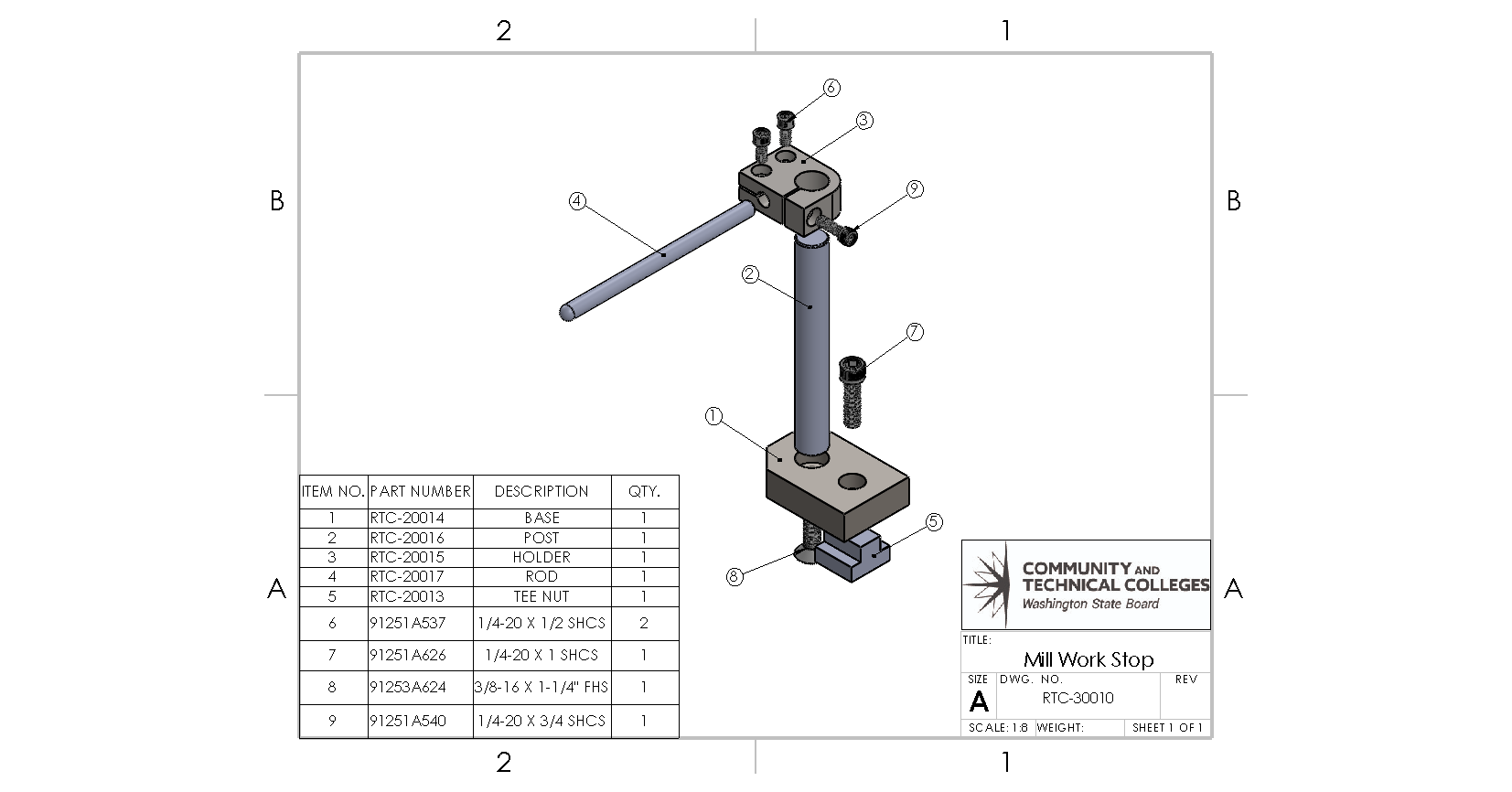
- Fig. 3.1: Chapter opening image: Assembly drawing of a mill stop to include a BOM and item tags by Damon Donner, for WA Open ProfTech, © SBCTC, CC BY 4.0
CAD is a tool that allows engineers to use the advanced technology of software based design to create digital models that can be transmitted electronically to manufacturers across the globe.
CAM software used by CNC programmers to create tool paths that are translated into G-Code and posted to machines, which ultimately create the part.
