10.11 Turning
Micky R. Jennings

Turning is the process of removing material from the outside diameter of the work. It usually comes after the facing operation establishes the end of the part. Turning can look like steps, tapers, radiuses, and more. Turning is generally performed with multiple roughing cuts and at least one finishing cut.
Step by step process for turning:
- Chuck on a piece of material, dial it in if needed, and face the end.
- The spindle speed for turning is the same as for facing.
- Select the feed rate on the quick-change gear box desired for the turning operation.
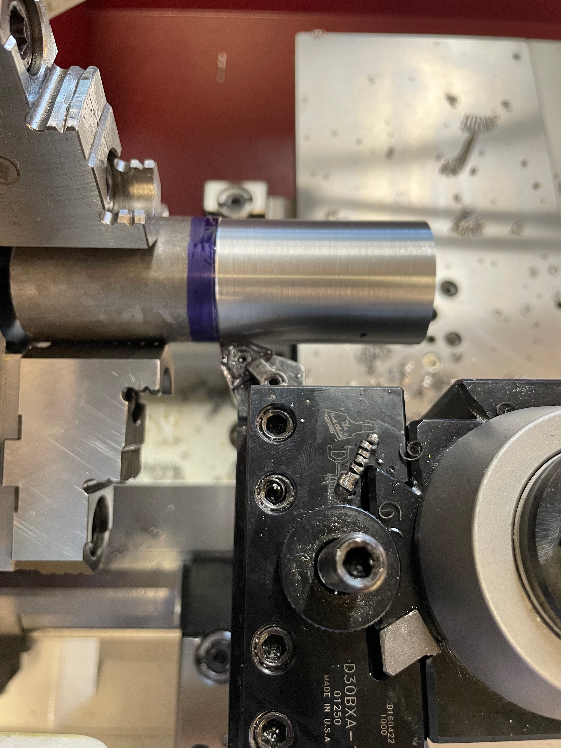
- Apply some layout dye to the outside of the part in the area to stop the turning operation.
- Turn on the spindle.
- Using an odd leg caliper, scribe a line from the face of the part the distance of the turned diameter.
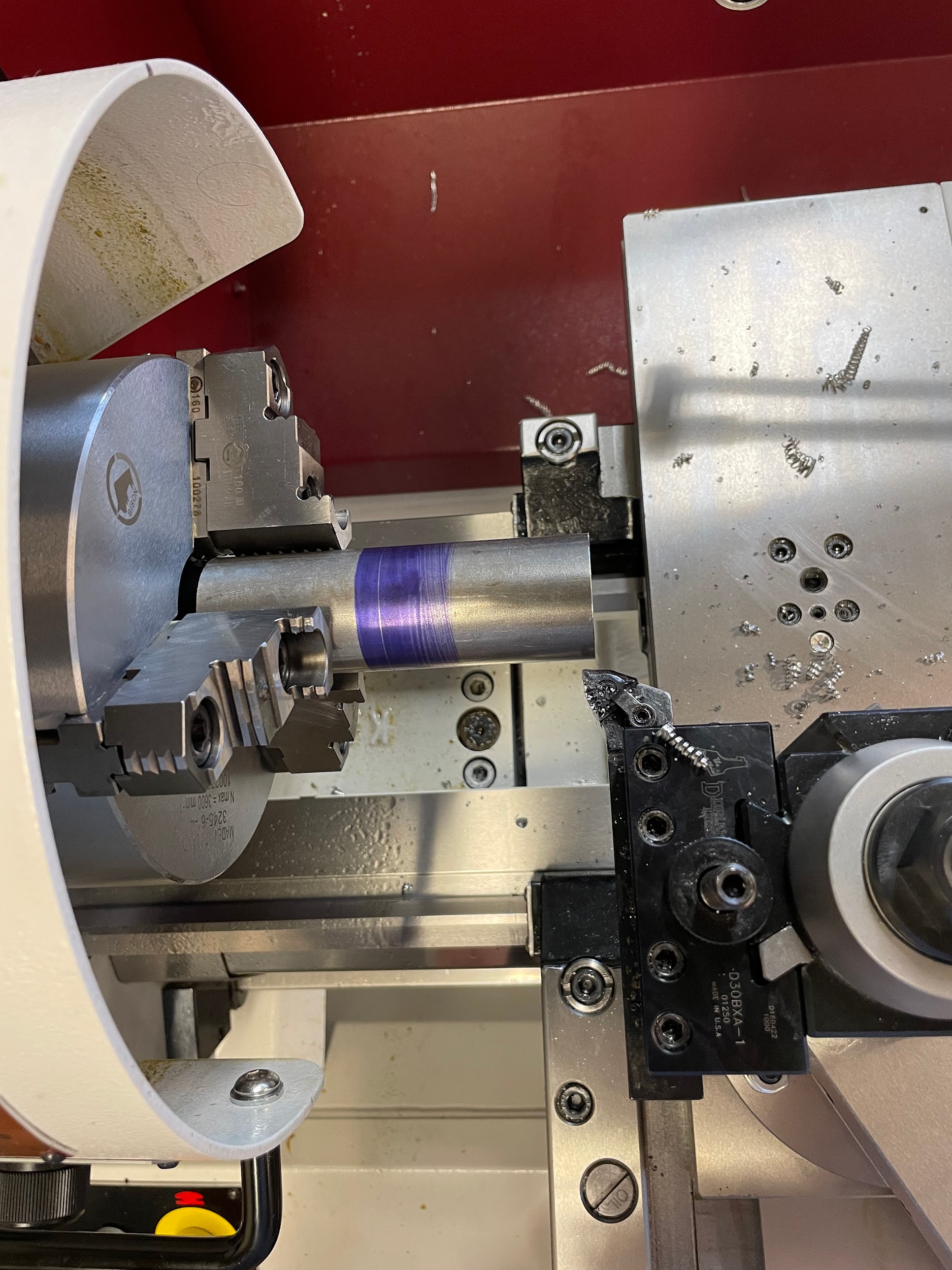
- Bring the carriage up about 1/8″ past the face of the part and close to the outside diameter.
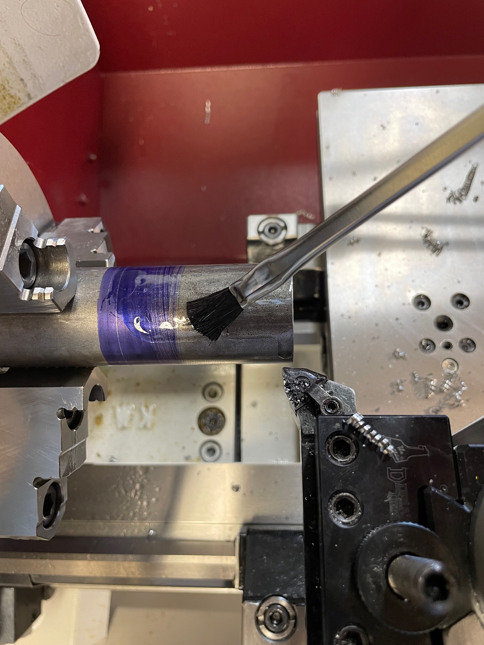
- Apply cutting oil if required.
- Gently touch off on the outside of the work by moving in with the cross slide.
- Set the cross-slide graduated collar to zero.
- Move the tool out in front of the face of the part and set an initial depth of cut.
- Engage the carriage power feed.
- Allow the tool to cut along the outside diameter of the part, stopping it about 1/8″ short of the scribed line.
- Move the rest of the distance by hand, reading the graduated collar carefully.
- Continue making successive cuts until reaching the desired diameter.
- Deburr edges with a file.
Step 4: Apply some layout dye to the outside of the part in the area to stop the turning operation.
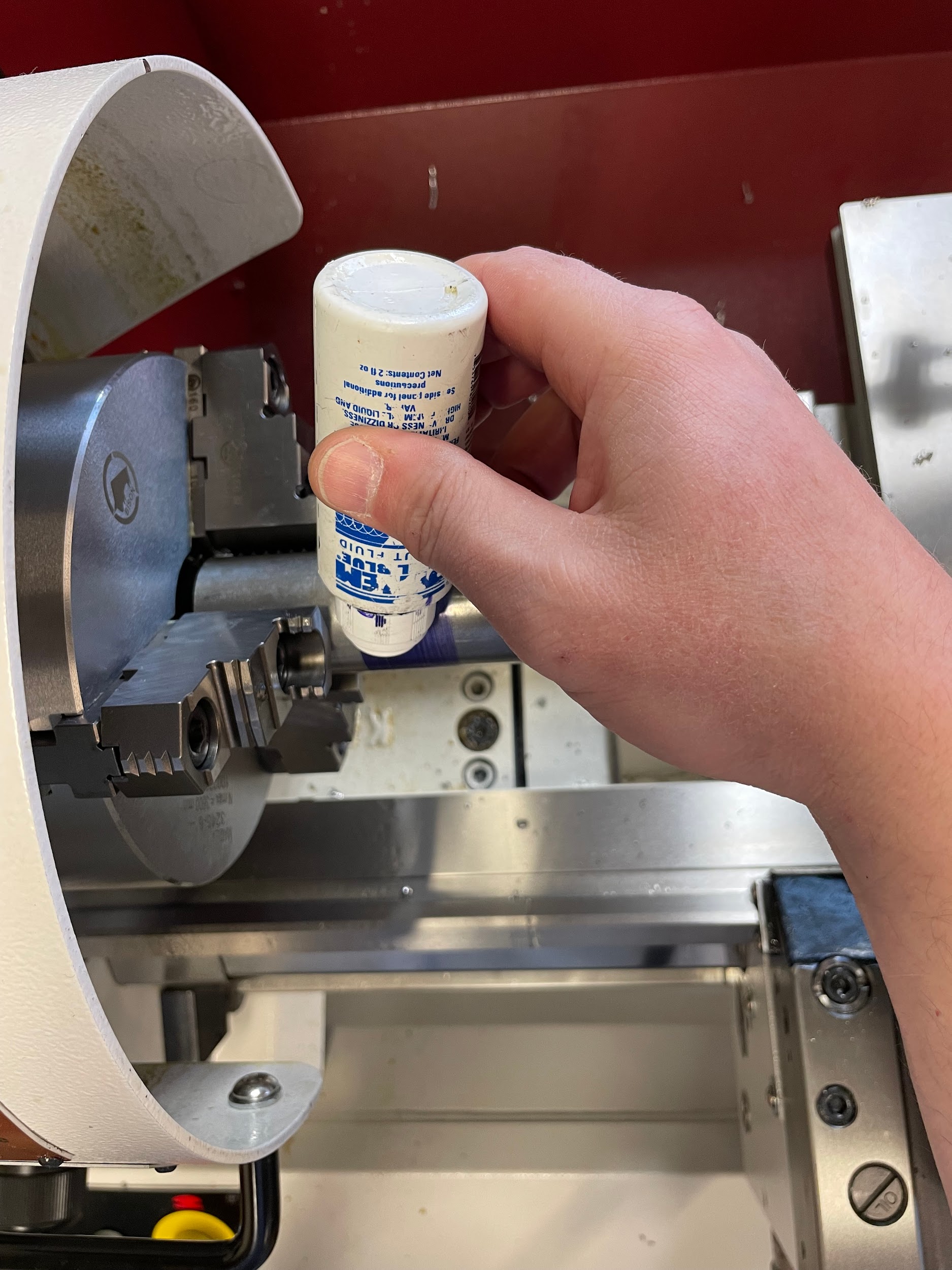
Step 4: Apply some layout dye to the outside of the part in the area to stop the turning operation.

Step 6: Using an odd leg caliper, scribe a line from the face of the part the distance of the turned diameter.
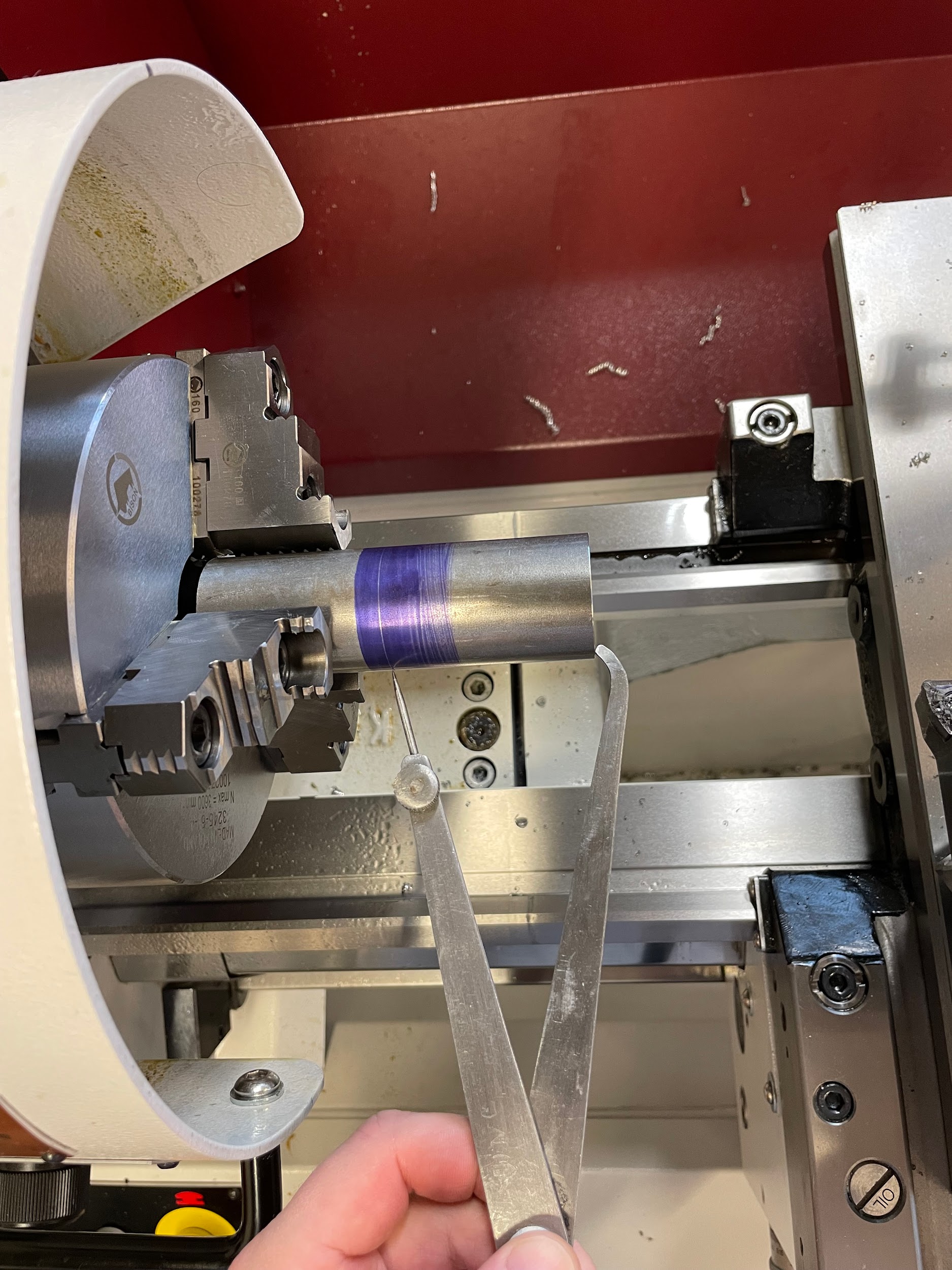
Step 6: Using an odd leg caliper, scribe a line from the face of the part the distance of the turned diameter.

Step 7: Bring the carriage up about 1/8″ past the face of the part and close to the outside diameter.
Step 8: Apply cutting oil if required.

Step 8: Apply cutting oil if required.
Step 9-13: Gently touch off on the outside of the work by moving in with the cross-slide. Set the cross-slide graduated collar to zero. Move the tool out in front of the face of the part and set an initial depth of cut. Engage the carriage power feed. Allow the tool to cut along the outside diameter of the part, stopping it about 1/8″ short of the scribed line.”

Step 13: Allow the tool to cut along the outside diameter of the part, stopping it about 1/8″ short of the scribed line.

Step 13: Allow the tool to cut along the outside diameter of the part, stopping it about 1/8″ short of the scribed line.
Attributions
- Figure 10.103: Turning by Micky R. Jennings, courtesy of Wenatchee Valley College, for WA Open ProfTech, © SBCTC, CC BY 4.0
- Figure 10.104: Layout dye by Micky R. Jennings, courtesy of Wenatchee Valley College, for WA Open ProfTech, © SBCTC, CC BY 4.0
- Video 10.38: Micky R. Jennings, courtesy of Wenatchee Valley College, for WA Open ProfTech, © SBCTC, CC BY 4.0
- Figure 10.105: Scribing by Micky R. Jennings, courtesy of Wenatchee Valley College, for WA Open ProfTech, © SBCTC, CC BY 4.0
- Video 10.39: Micky R. Jennings, courtesy of Wenatchee Valley College, for WA Open ProfTech, © SBCTC, CC BY 4.0
- Figure 10.106: Prep for cutting by Micky R. Jennings, courtesy of Wenatchee Valley College, for WA Open ProfTech, © SBCTC, CC BY 4.0
- Video 10.40: Micky R. Jennings, courtesy of Wenatchee Valley College, for WA Open ProfTech, © SBCTC, CC BY 4.0
- Figure 10.107: Cutting oil by Micky R. Jennings, courtesy of Wenatchee Valley College, for WA Open ProfTech, © SBCTC, CC BY 4.0
- Video 10.41: Micky R. Jennings, courtesy of Wenatchee Valley College, for WA Open ProfTech, © SBCTC, CC BY 4.0
- Video 10.42: Micky R. Jennings, courtesy of Wenatchee Valley College, for WA Open ProfTech, © SBCTC, CC BY 4.0
- Figure 10.108: Turning by Micky R. Jennings, courtesy of Wenatchee Valley College, for WA Open ProfTech, © SBCTC, CC BY 4.0
The process of using a turning tool to cut parallel to the rotational axis of the lathe.
