10.13 Taper Turning
Micky R. Jennings
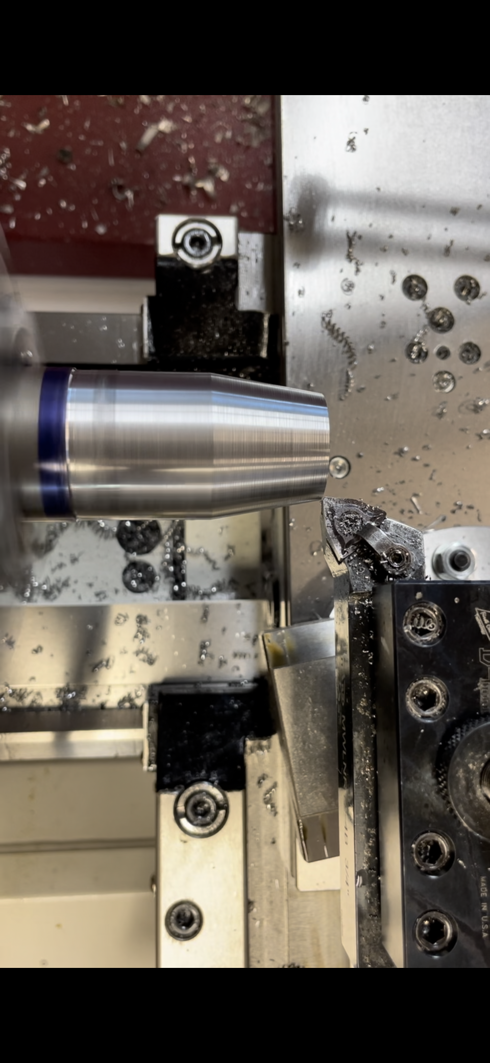
Taper turning is the process of producing a taper on the workpiece. Tapers can come in many forms and can be cut with multiple different methods. Short tapers can be cut using the compound rest. Long, shallow tapers will need to be made with the tailstock offset method or the use of a taper attachment. Taper turning is generally performed with multiple roughing cuts and at least one finishing cut.
Tailstock Offset Method
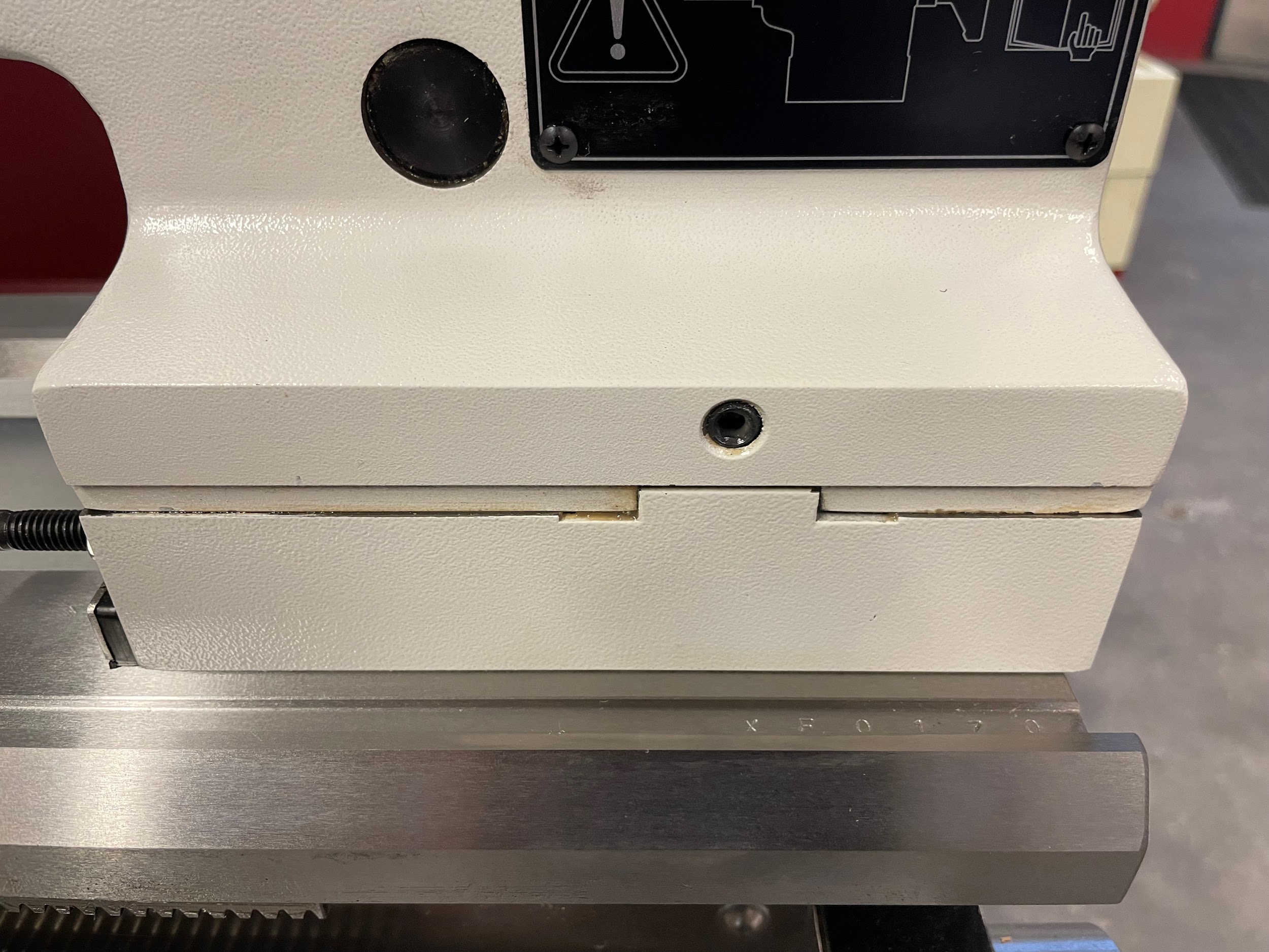
The tailstock offset method is a way of moving the upper portion of the tailstock out of line with the center rotation of the lathe spindle. The body of the tailstock can be moved in and out independent of the base by loosening and tightening bolts on the front and back of the tailstock.
Step by step process for creating a taper using the tailstock offset method:
- Hold a part between centers. It helps if the center drills used are the bell type. This is because the part will need to pivot slightly on the centers as it revolves. This is easier on the rounded portion of the bell center drill mark.
- Calculate the taper per inch of the feature to be machined.
- Apply that taper per inch to the entire length of the part. Half of this amount is approximately how much the tailstock should be offset.
- Use a magnetic base to apply a drop indicator to the side of the tailstock and adjust it by the amount calculated.
- Mount the work between centers.
- With the spindle static, run a drop indicator along a measured length and observe the taper per inch. This is only half the amount of taper that will exist when the part is cut because, when machining on a lathe, the material removed on one side of the part is also removed from the other side.
- Readjust and recheck until the taper per inch is correct.
- Now the part can be machined with a standard carriage turning operation, and because the part is held crooked to the centerline of the spindle, a taper will be created.
Taper Attachment Method
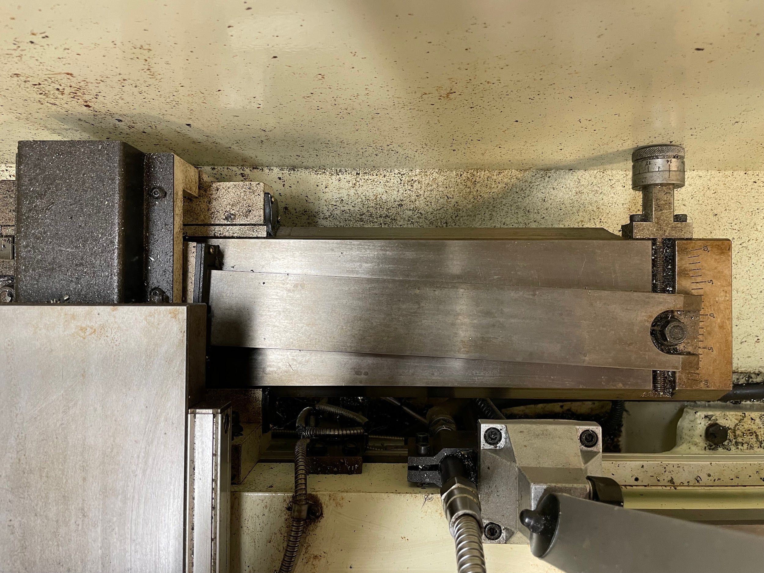
A taper attachment is a device that attaches to the back of a lathe and aids in making shallow tapers by automatically moving the cross- slide while the carriage is feeding axially. It does this by replacing the nut that normally creates the movement for the cross-slide with a shoe that rides on a bar that is adjusted to a precise angle or taper per inch. Taper attachment types and the mounting method vary with each machine. For this reason, it is best to refer to the operator’s manual for proper set-up and use.
Compound Rest Method
The compound rest method is the simplest and most versatile way to create a taper. An angle anywhere between 0 and 90 degrees can be created. A couple of the downsides of the compound method are that the length of taper is limited by the movement length of the compound rest, and there is no power feed option.
Step by step process for creating a taper using the compound rest:
- Chuck up the part that needs to have a taper.
- Calculate the taper in degrees if it isn’t already called out on the print.
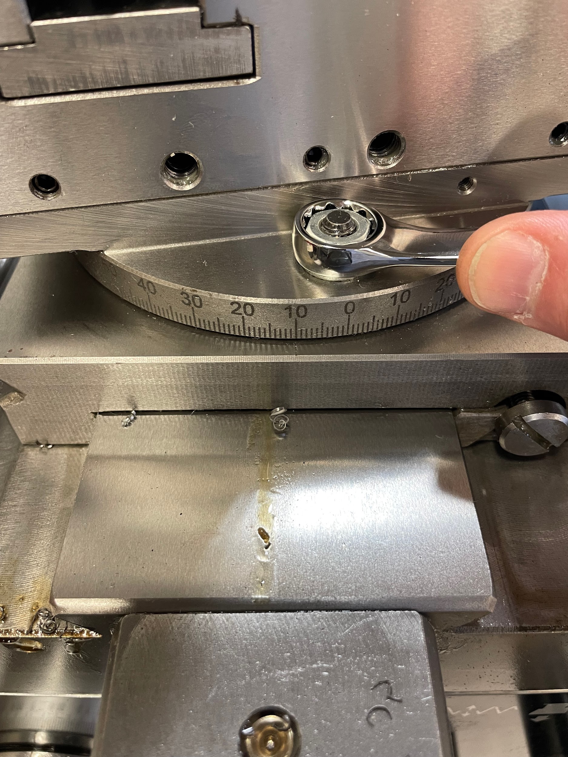
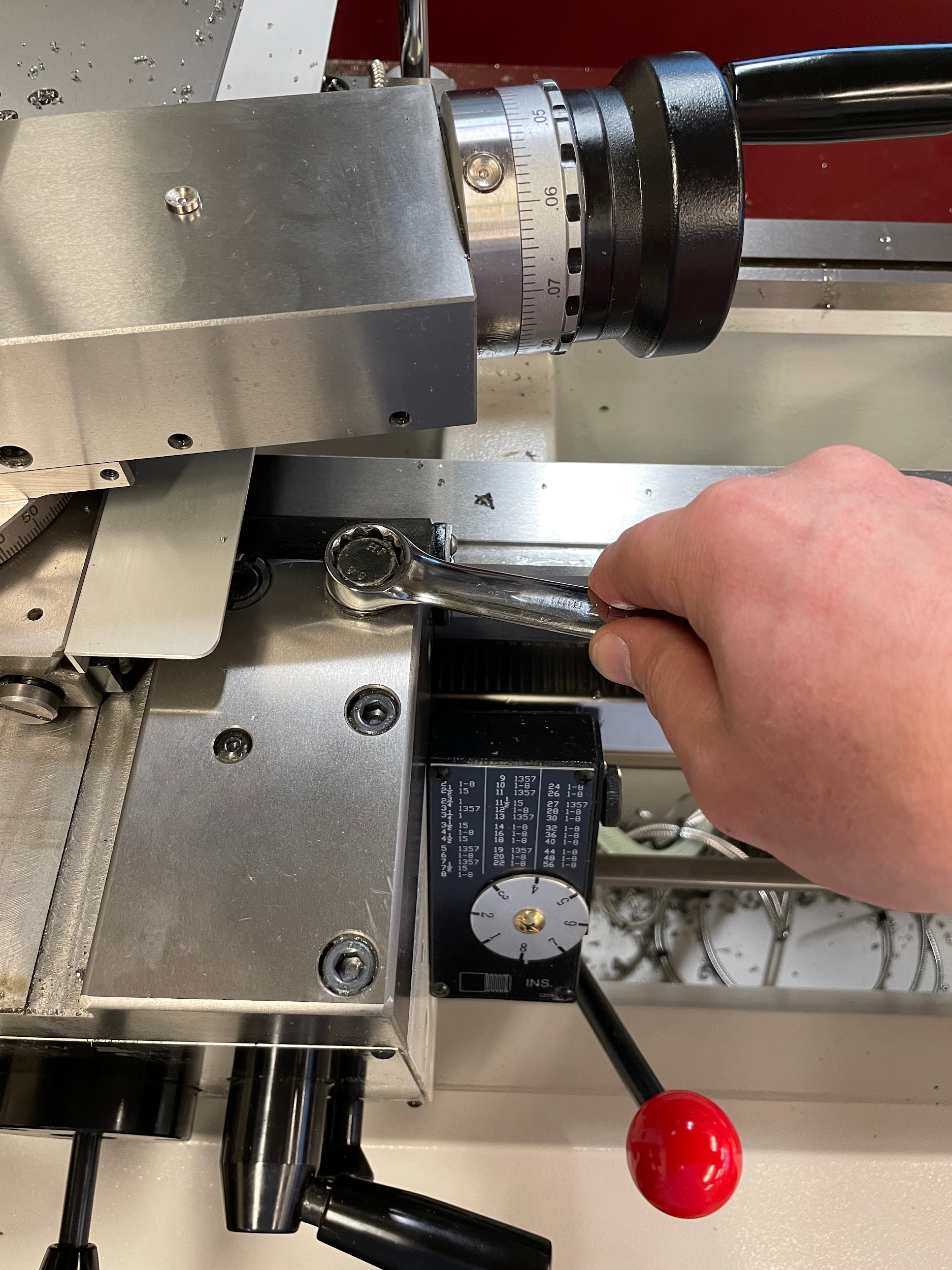
- Loosen the bolts holding the compound rest and adjust the compound as close as possible to the needed degree using the graduated markings.
- Tighten the bolts.
- Align the tool post.
- Set up a drop indicator on a mag base so that the indicator plunger is perpendicular to the workpiece.
- Press the plunger against the work a few hundred thousandths.
- Remove backlash in compound movement.
- Zero drop indicator.
- Move the compound rest by a known distance.
- Read the movement on the indicator.
- Now that those two measurements are documented, use right angle trigonometry to calculate the precise angle for the compound. Let the known distance be the hypotenuse and the indicator reading be one of the legs.
- Compare this calculated angle to the one from the print. If it isn’t within tolerance, decide which way the compound needs to move, and repeat the steps of moving and checking the angle of the compound.
- Load a turning tool on the tool post.
- Position the tool off the end of the work by about 1/8″. Make sure the compound will have enough travel to cut the entire taper.
- Lock the carriage.
- Oil the part if necessary.
- Use the cross-slide to set the initial depth of cut.
- Use the compound to make the tapered cut in one smooth motion.
- Continue making successive cuts until there is a sufficient amount of taper to measure the angle.
- Unlock the carriage.
- Mount the indicator on the machine again and load it on the end of the part.
- Remove the backlash in the carriage.
- This time, the carriage will be moved by a known amount.
- Read the movement on the indicator.
- Use right angle trigonometry to calculate the precise angle of the part. Let the known distance be one leg and the indicator reading be the other leg.
- Compare this calculation to the print and adjust if necessary.
- Continue making successive cuts until the taper is cut to size.
Step 3: Loosen the bolts holding the compound rest and adjust the compound as close as possible to the needed degree using the graduated markings.
Step 5: Align the tool post.
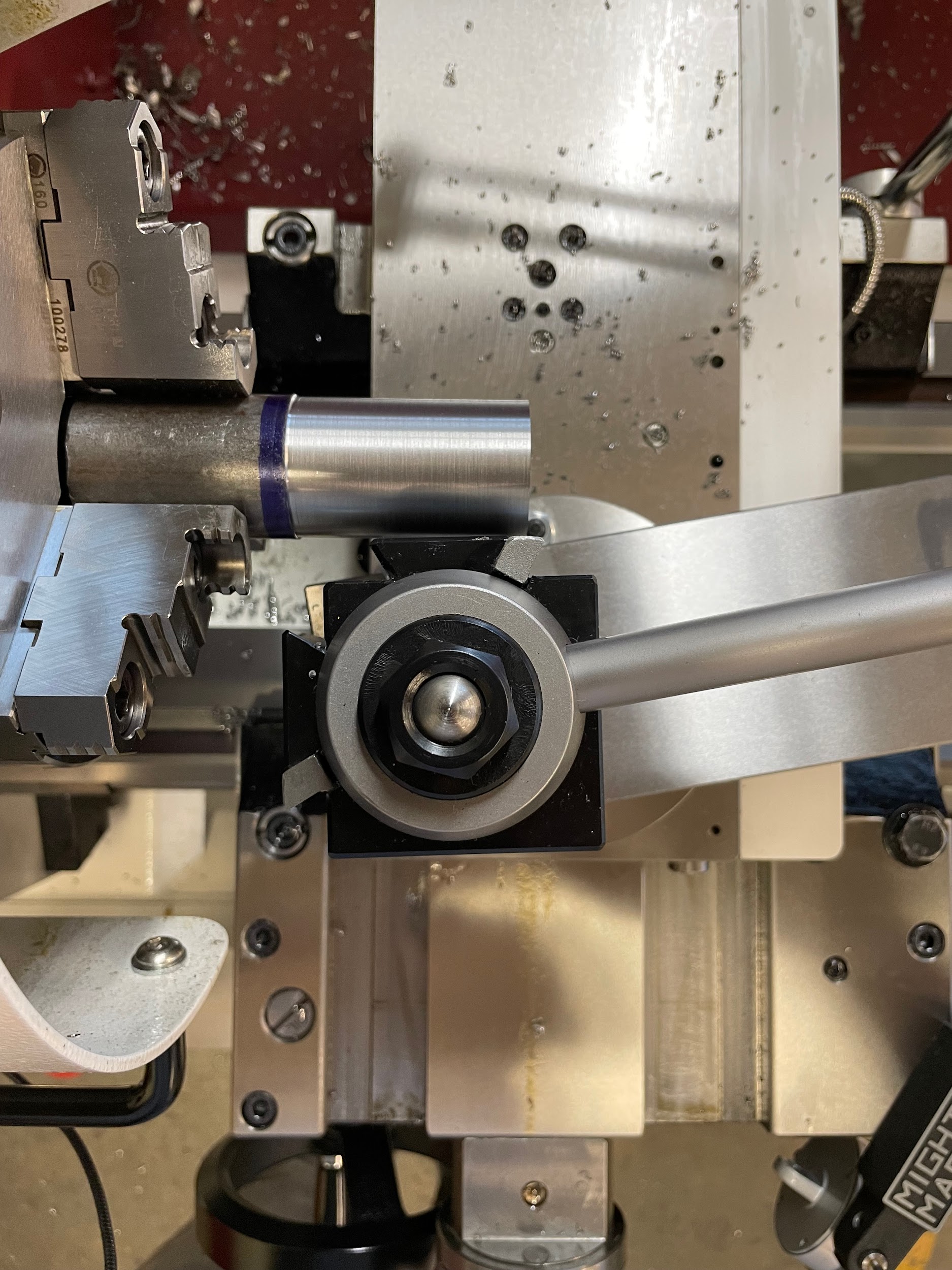
Step 5: Align the tool post.

Step 7: Press the plunger against the work a few hundred thousandths.

Step 8: Remove backlash in compound movement.

Step 10: Move the compound rest by a known distance.

Step 10: Move the compound rest by a known distance.

Step 13: Compare this calculated angle to the one from the print. If it isn’t within tolerance, decide which way the compound needs to move, and repeat the steps of moving and checking the angle of the compound.

Step 16: Lock the carriage.
Step 17: Oil the part if necessary.
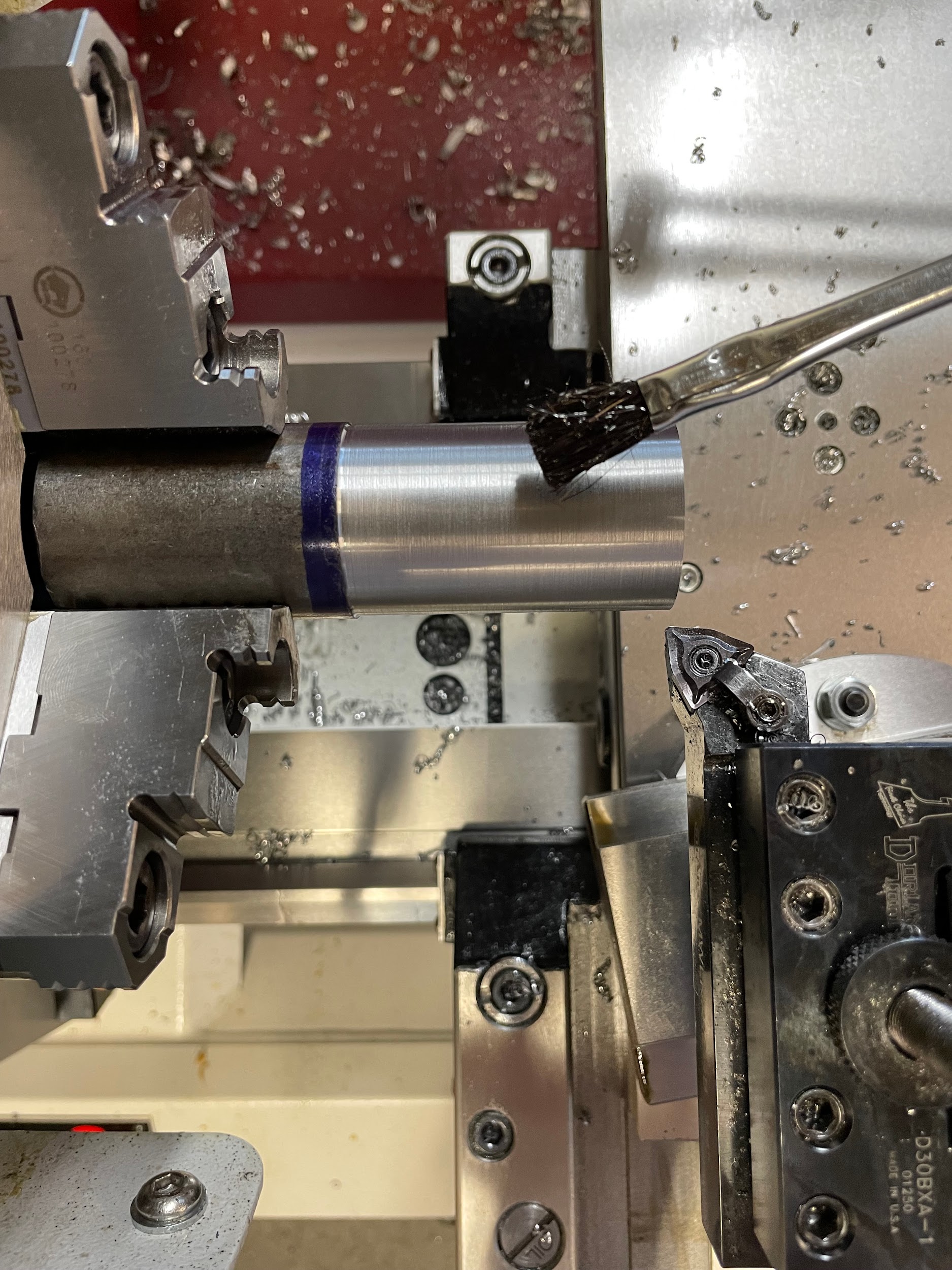
Step 17: Oil the part if necessary.

Step 18-20: Use the cross-slide to set the initial depth of cut. Use the compound to make the tapered cut in one smooth motion. Continue making successive cuts until there is a sufficient amount of taper to measure the angle.

Step 20: Continue making successive cuts until there is a sufficient amount of taper to measure the angle.

Step 24: This time, the carriage will be moved by a known amount.

Taper Measurement
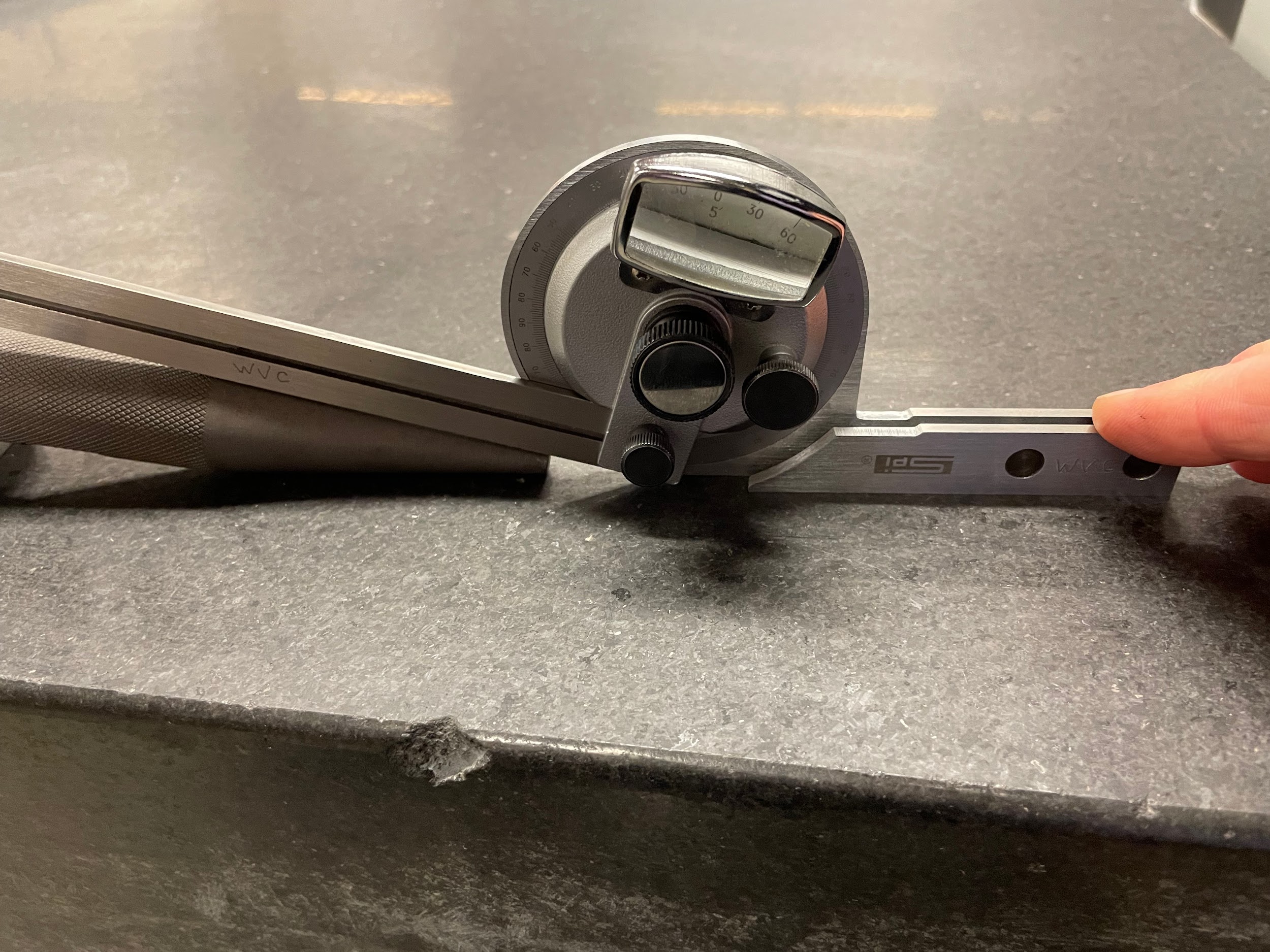
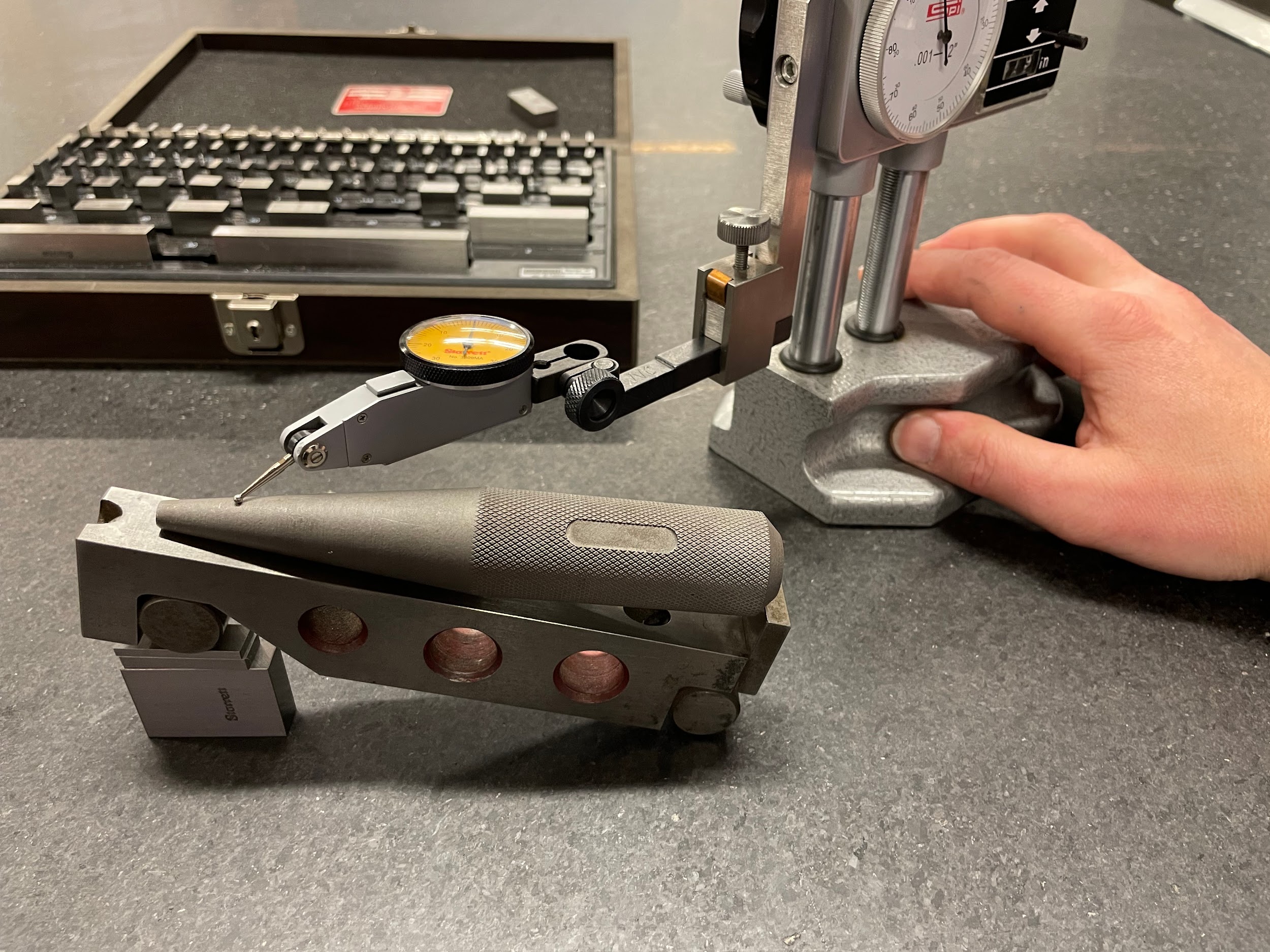
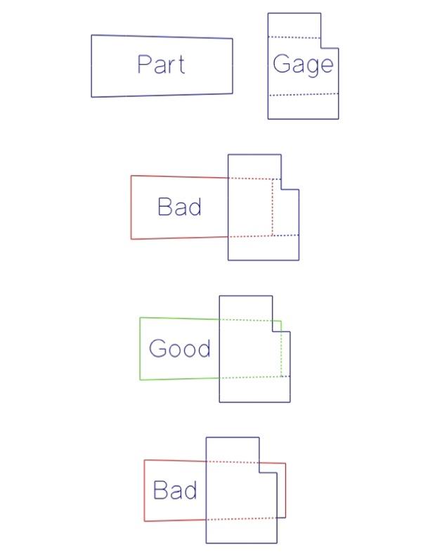
Measuring the angle of taper can be conducted on a lathe as described above. This method offers a fairly high degree of accuracy and has the advantage of measuring while the part is still on the machine. Other methods would be using a bevel protractor or a sine bar. A bevel protractor gives a measurement much more accurate than the protractor head of a combination square, but the bevel protractor’s resolution is limited to 5 minutes. If accuracy greater than that is required, use of a sine bar and gage blocks is needed. These methods only measure angle, and not size. It is difficult to measure the positional size of a taper without tapered ring gages. Tapered ring gages are sometimes standardized but are often custom gages that are placed over the end of the taper. Measurement from the part to the gage is taken to see if the taper is the correct diameter.
Attributions
- Figure 10.119: Taper turning by Micky R. Jennings, courtesy of Wenatchee Valley College, for WA Open ProfTech, © SBCTC, CC BY 4.0
- Figure 10.120: Tailstock adjustment by Micky R. Jennings, courtesy of Wenatchee Valley College, for WA Open ProfTech, © SBCTC, CC BY 4.0
- Figure 10.121: Taper attachment by Micky R. Jennings, courtesy of Wenatchee Valley College, for WA Open ProfTech, © SBCTC, CC BY 4.0
- Figure 10.122: Loosen compound rest by Micky R. Jennings, courtesy of Wenatchee Valley College, for WA Open ProfTech, © SBCTC, CC BY 4.0
- Figure 10.123: Tool post alignment by Micky R. Jennings, courtesy of Wenatchee Valley College, for WA Open ProfTech, © SBCTC, CC BY 4.0
- Video 10.57: Micky R. Jennings, courtesy of Wenatchee Valley College, for WA Open ProfTech, © SBCTC, CC BY 4.0
- Video 10.58: Micky R. Jennings, courtesy of Wenatchee Valley College, for WA Open ProfTech, © SBCTC, CC BY 4.0
- Video 10.59: Micky R. Jennings, courtesy of Wenatchee Valley College, for WA Open ProfTech, © SBCTC, CC BY 4.0
- Video 10.60: Micky R. Jennings, courtesy of Wenatchee Valley College, for WA Open ProfTech, © SBCTC, CC BY 4.0
- Video 10.61: Micky R. Jennings, courtesy of Wenatchee Valley College, for WA Open ProfTech, © SBCTC, CC BY 4.0
- Video 10.62: Micky R. Jennings, courtesy of Wenatchee Valley College, for WA Open ProfTech, © SBCTC, CC BY 4.0
- Figure 10.124: Carriage locking by Micky R. Jennings, courtesy of Wenatchee Valley College, for WA Open ProfTech, © SBCTC, CC BY 4.0
- Figure 10.125: Cutting oil by Micky R. Jennings, courtesy of Wenatchee Valley College, for WA Open ProfTech, © SBCTC, CC BY 4.0
- Video 10.63: Micky R. Jennings, courtesy of Wenatchee Valley College, for WA Open ProfTech, © SBCTC, CC BY 4.0
- Video 10.64: Micky R. Jennings, courtesy of Wenatchee Valley College, for WA Open ProfTech, © SBCTC, CC BY 4.0
- Video 10.65: Micky R. Jennings, courtesy of Wenatchee Valley College, for WA Open ProfTech, © SBCTC, CC BY 4.0
- Video 10.66: Micky R. Jennings, courtesy of Wenatchee Valley College, for WA Open ProfTech, © SBCTC, CC BY 4.0
- Figure 10.126: Bevel protractor by Micky R. Jennings, courtesy of Wenatchee Valley College, for WA Open ProfTech, © SBCTC, CC BY 4.0
- Figure 10.127: Sine bar by Micky R. Jennings, courtesy of Wenatchee Valley College, for WA Open ProfTech, © SBCTC, CC BY 4.0
- Figure 10.128: Tapered ring gage use by Micky R. Jennings, courtesy of Wenatchee Valley College, for WA Open ProfTech, © SBCTC, CC BY 4.0
The process of cutting conical tapered features on the lathe.
