10.16 Grooving
Micky R. Jennings
Grooving is the process of creating a recessed slot on the outside diameter (OD), inside diameter (ID), or face of a part. This slot can be made in as few as one plunging cut or in multiple cuts. A common purpose for grooving it is to create a recess for “O” rings or snap rings. Grooving can also be used to make custom shaped or tapered features, similar to the grooves of a pulley.
Step by step process for cutting a single plunge groove:
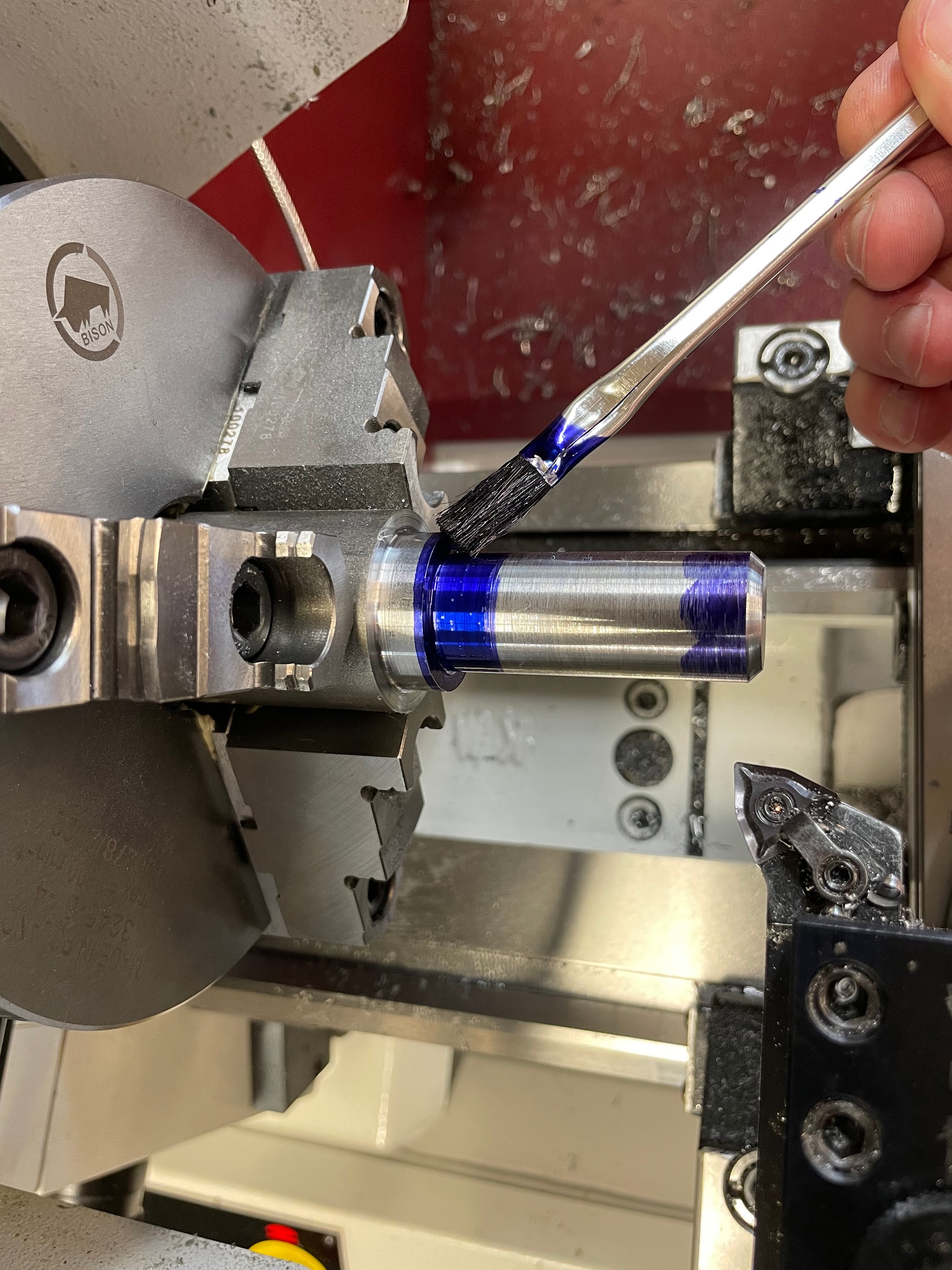
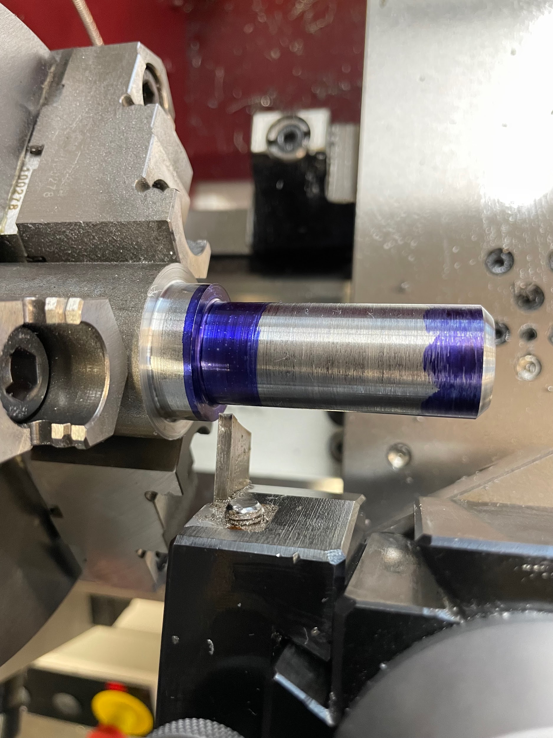
- Apply layout fluid to the outside diameter of the part.
- Using odd leg calipers, scribe lines that will define the groove.
- Calculate the spindle speed based on the largest diameter the tool will cut. Grooving is often done at a slower speed than turning. Reduce spindle speed to about 1/4 of general turning speed.
- Load a grooving tool into a holder and onto the tool post.
- Adjust the length of the tool.
- Reset the tool height.
- Start the spindle.
- Touch the grooving tool off to the face of the work, or wherever the groove is referenced from, and set the carriage handwheel to zero.
- Move over the axial distance needed to position the tool.
- Lock the carriage.
- Bring the tool close to the outside diameter and visually check the scribed lines.
- Gently bring the tool in with the cross slide and touch off the tool on the outside diameter.
- Set the graduated collar on the cross slide to zero.
- Lube the tool.
- Cut into the part about .020 and back out.
- Check the measurement from the shallow edges of the groove to the reference feature.
- Measure the diameter of the bottom of the groove and calculate remaining material to remove.
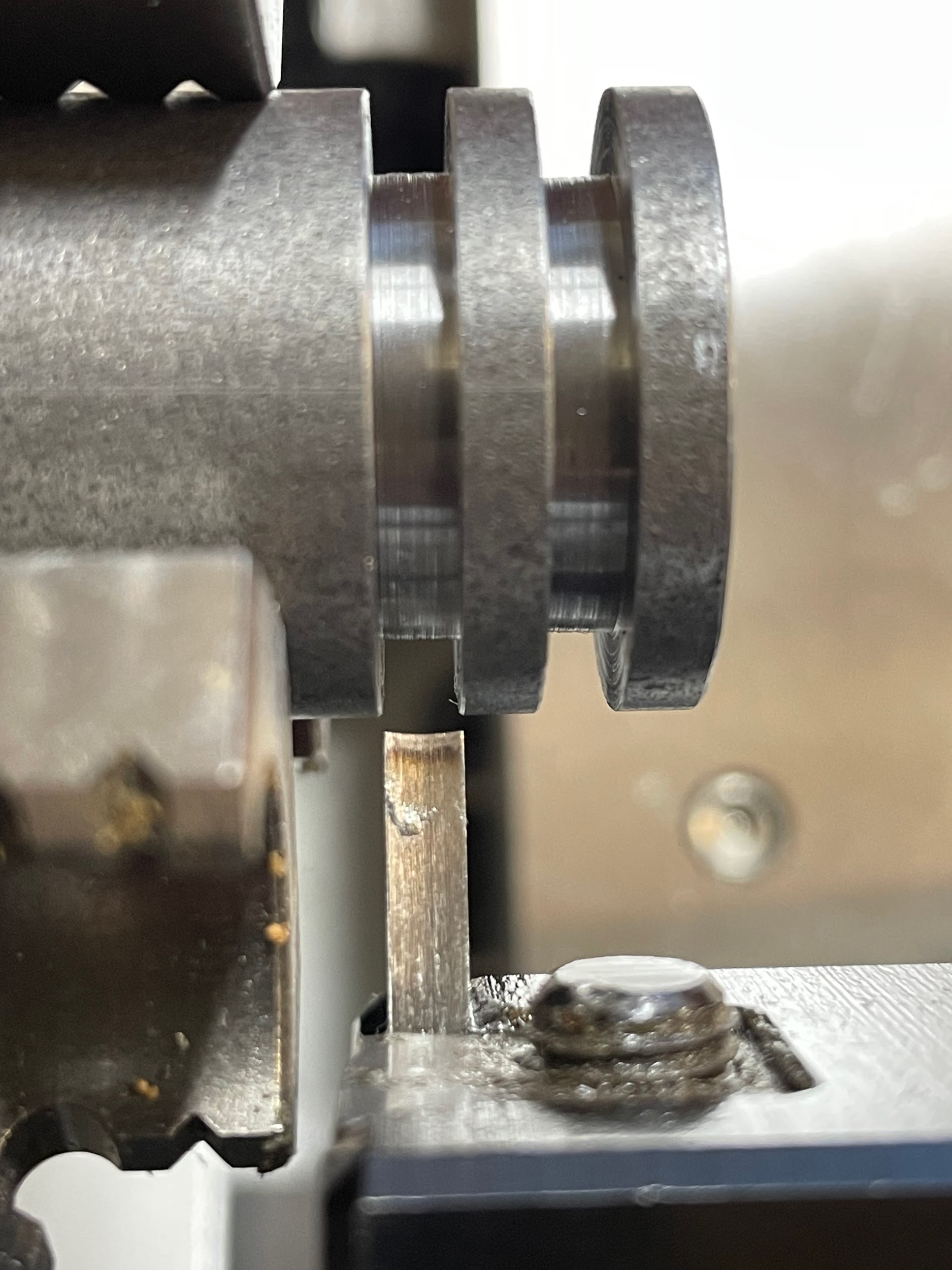
- Slowly cut the groove to the final depth. Keep a nice even feed and allow the chip to curl into a spiral shape on top of the tool while applying an occasional drop of cutting oil.
- Deburr the edges of the groove with a file.
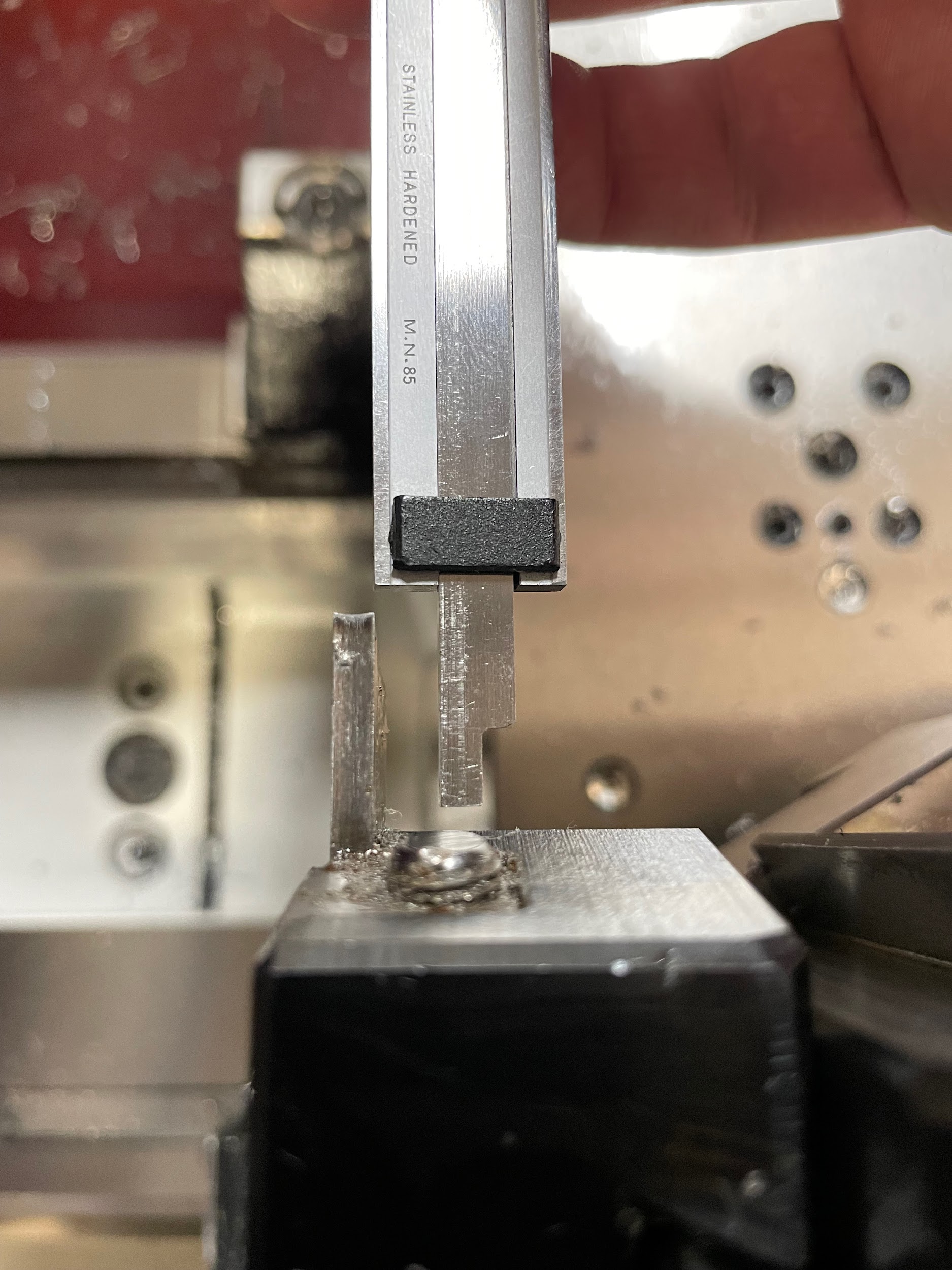
Step 5: Adjust the length of the tool.
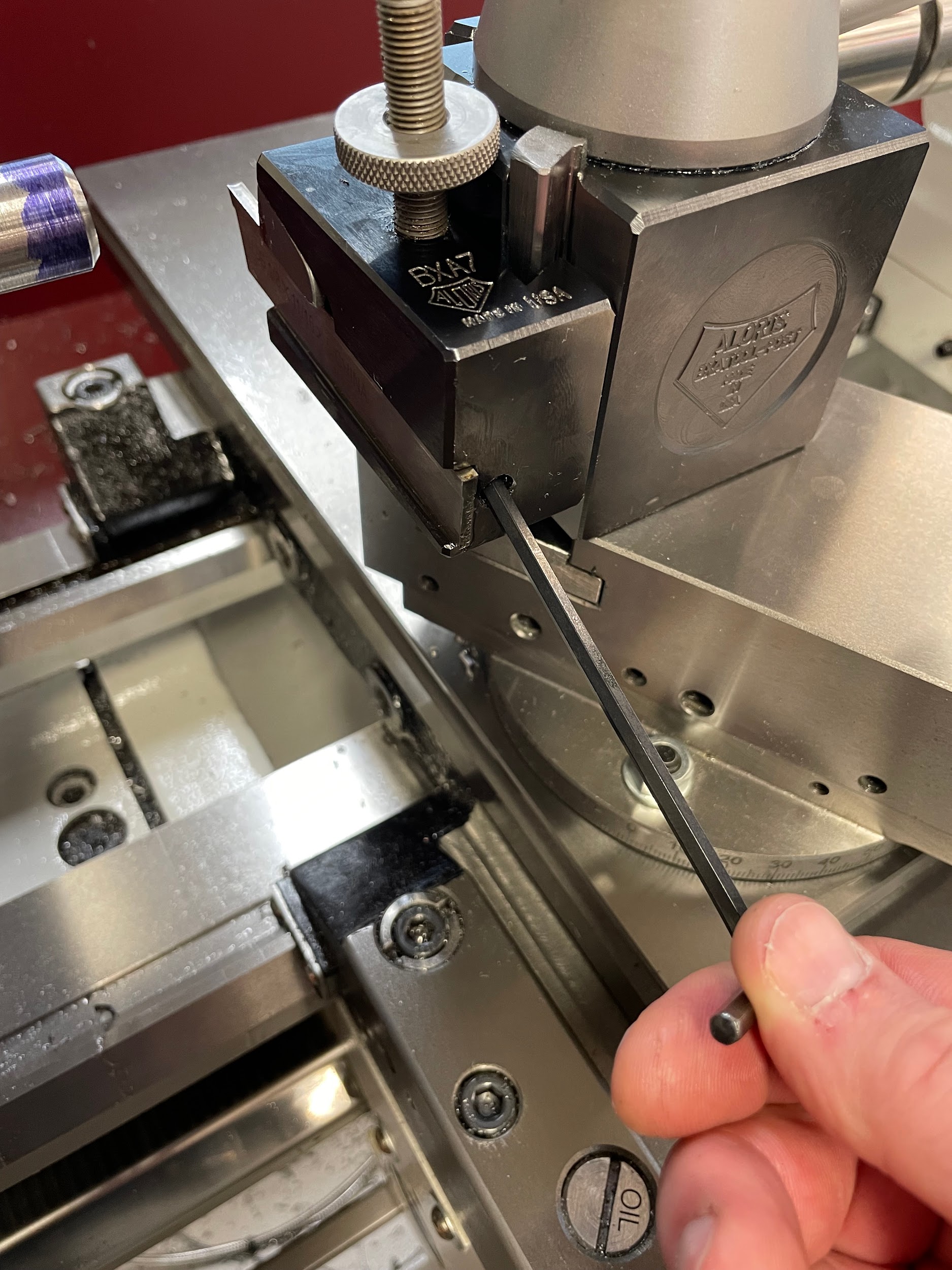
Step 5: Adjust the length of the tool.

Step 5: Adjust the length of the tool.

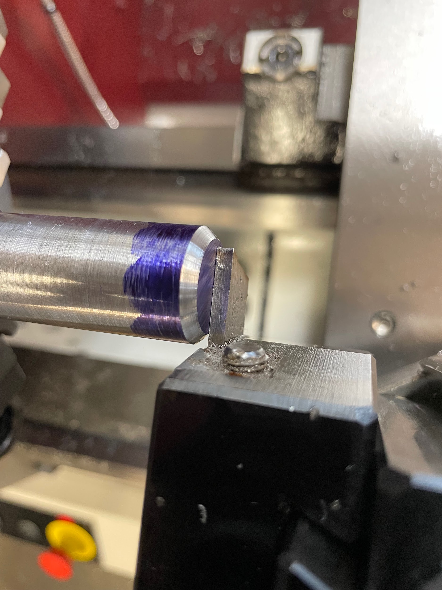
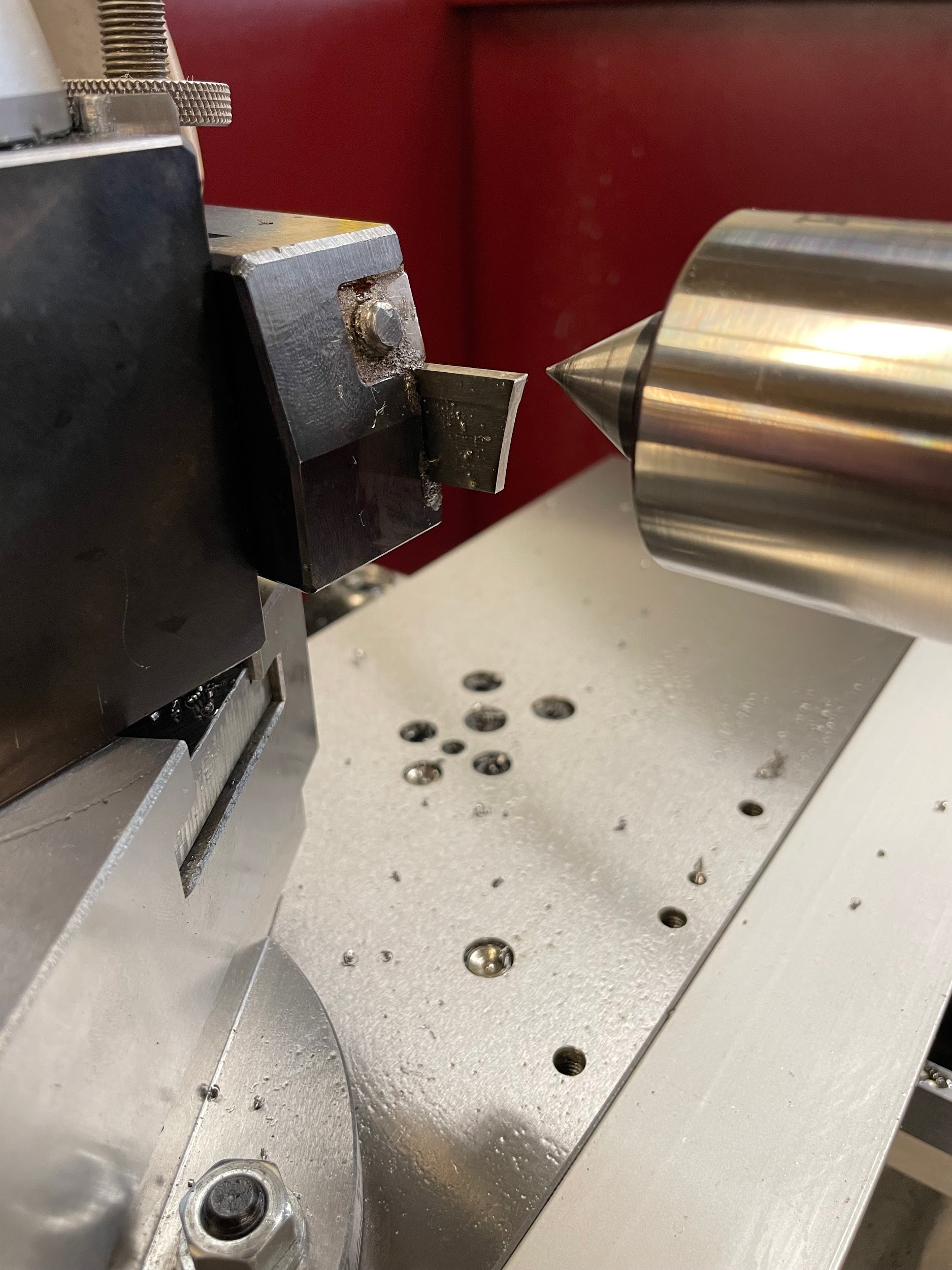
Step 6: Reset the tool height.

Step 8: Touch the grooving tool off to the face of the work, or wherever the groove is referenced from, and set the carriage handwheel to zero.
Step 8: Touch the grooving tool off to the face of the work, or wherever the groove is referenced from, and set the carriage handwheel to zero.

Step 18: Slowly cut the groove to the final depth. Keep a nice even feed and allow the chip to curl into a spiral shape on top of the tool while applying an occasional drop of cutting oil.

Step by step process for cutting a multi-plunge groove:
- Apply layout fluid to the outside diameter of the part.
- Using odd leg calipers, scribe lines that will define the groove.
- Calculate the spindle speed based on the largest diameter the tool will cut. Grooving is often done at a slower speed than turning. Reduce spindle speed to about 1/4 of the general turning speed.
- Load a grooving tool into a holder and onto the tool post.
- Adjust the length of the tool.
- Reset the tool height.
- Start the spindle.
- Position the grooving tool in the center of the scribed lines.
- Set the graduated collar of the carriage to zero.
- Lock the carriage.
- Gently bring the tool in with the cross slide and touch off the tool on the outside diameter.
- Set the graduated collar on the cross slide to zero.
- Lube the tool.
- Cut into the part about .020 and back out.
- Measure the diameter of the bottom of the groove and calculate remaining material to remove.
- Slowly cut the groove .005 to .010 from the final depth. Keep a nice even feed and allow the chip to curl into a spiral shape on top of the tool while applying an occasional drop of cutting oil.
- Measure an edge for groove placement from a reference feature and calculate distance remaining in that direction.
- Make successive plunge cuts at about 75% to 95% step over of the tool’s width until desired groove edge placement is achieved.
- Note handwheel reading on final plunge cut.
- Measure the groove’s width and calculate the remaining material to remove.
- Make successive plunge cuts in the opposite direction from the starting point at about 75% to 95% step over of the tool’s width until desired groove width is achieved.
- On the last plunge cut, remove material to final depth.
- Unlock the carriage while at final depth and slowly feed the carriage towards the reading on the hand wheel where the opposite side of the groove finished. This will finish the bottom of the groove nicely and remove any inconsistent plunge marks.
- Deburr the edges of the groove with a file.
Step 1: Apply layout fluid to the outside diameter of the part.
Step 5: Adjust the length of the tool.

Step 5: Adjust the length of the tool.
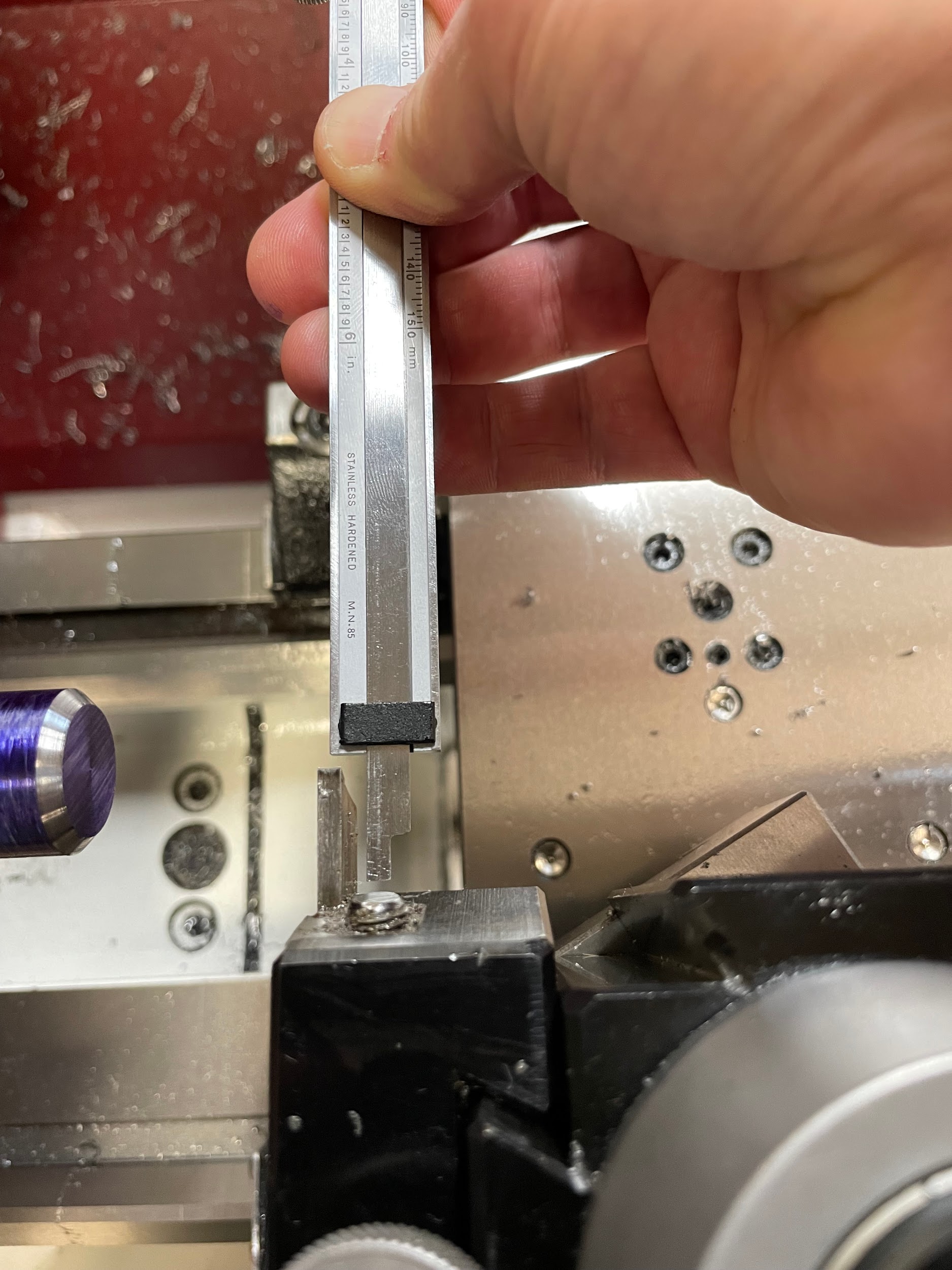
Step 5: Adjust the length of the tool.
Step 6: Reset the tool height.
Step 8: Position the grooving tool in the center of the scribed lines.
Step 11: Gently bring the tool in with the cross slide and touch off the tool on the outside diameter.

Step 13: Lube the tool.

Step 16: Slowly cut the groove .005 to .010 from the final depth. Keep a nice even feed and allow the chip to curl into a spiral shape on top of the tool while applying an occasional drop of cutting oil.

Step 16: Slowly cut the groove .005 to .010 from the final depth. Keep a nice even feed and allow the chip to curl into a spiral shape on top of the tool while applying an occasional drop of cutting oil.

Step 22-23: On the last plunge cut, remove material to final depth. Unlock the carriage while at final depth and slowly feed the carriage towards the reading on the hand wheel where the opposite side of the groove finished. This will finish the bottom of the groove nicely and remove any inconsistent plunge marks.

Step 24: Deburr the edges of the groove with a file.
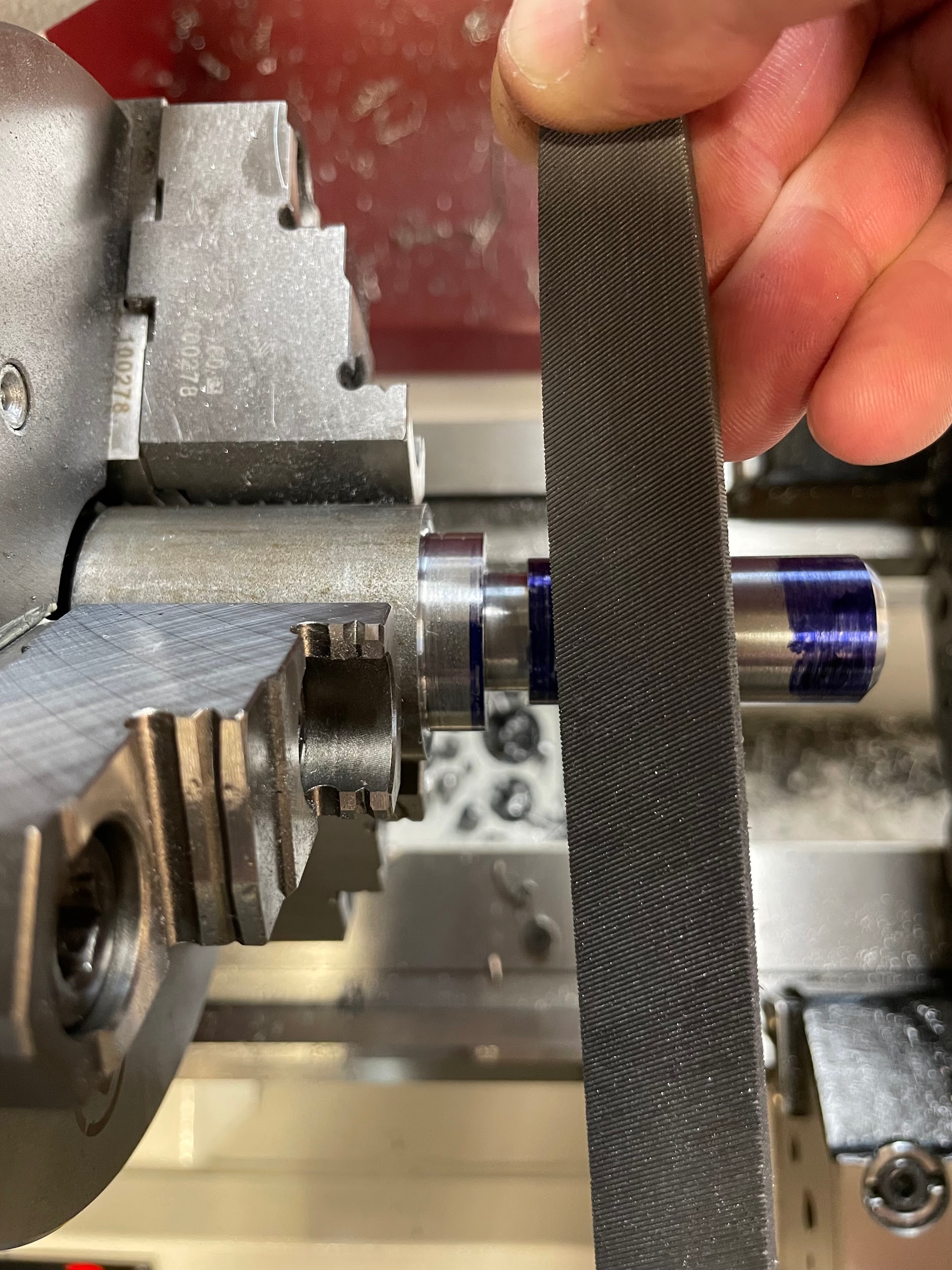
Step 24: Deburr the edges of the groove with a file.

Attributions
- Figure 10.158: Finished grooves by Micky R. Jennings, courtesy of Wenatchee Valley College, for WA Open ProfTech, © SBCTC, CC BY 4.0
- Figure 10.159: Adjusting a part off blade. by Micky R. Jennings, courtesy of Wenatchee Valley College, for WA Open ProfTech, © SBCTC, CC BY 4.0
- Figure 10.160: Measuring a part off blade by Micky R. Jennings, courtesy of Wenatchee Valley College, for WA Open ProfTech, © SBCTC, CC BY 4.0
- Figure 10.161: Measuring a part off blade 2 by Micky R. Jennings, courtesy of Wenatchee Valley College, for WA Open ProfTech, © SBCTC, CC BY 4.0
- Figure 10.162: Checking tool height by Micky R. Jennings, courtesy of Wenatchee Valley College, for WA Open ProfTech, © SBCTC, CC BY 4.0
- Figure 10.163: Checking the alignment by Micky R. Jennings, courtesy of Wenatchee Valley College, for WA Open ProfTech, © SBCTC, CC BY 4.0
- Video 10.80: Micky R. Jennings, courtesy of Wenatchee Valley College, for WA Open ProfTech, © SBCTC, CC BY 4.0
- Figure 10.164: Finished grooves by Micky R. Jennings, courtesy of Wenatchee Valley College, for WA Open ProfTech, © SBCTC, CC BY 4.0
- Figure 10.165: Applying layout dye by Micky R. Jennings, courtesy of Wenatchee Valley College, for WA Open ProfTech, © SBCTC, CC BY 4.0
- Figure 10.166: Adjusting a part off blade by Micky R. Jennings, courtesy of Wenatchee Valley College, for WA Open ProfTech, © SBCTC, CC BY 4.0
- Figure 10.167: Measuring a part off blade by Micky R. Jennings, courtesy of Wenatchee Valley College, for WA Open ProfTech, © SBCTC, CC BY 4.0
- Figure 10.168: Measuring a part off blade 2 by Micky R. Jennings, courtesy of Wenatchee Valley College, for WA Open ProfTech, © SBCTC, CC BY 4.0
- Figure 10.169: Checking tool height by Micky R. Jennings, courtesy of Wenatchee Valley College, for WA Open ProfTech, © SBCTC, CC BY 4.0
- Figure 10.170: Positioning the tool by Micky R. Jennings, courtesy of Wenatchee Valley College, for WA Open ProfTech, © SBCTC, CC BY 4.0
- Video 10.81: Micky R. Jennings, courtesy of Wenatchee Valley College, for WA Open ProfTech, © SBCTC, CC BY 4.0
- Video 10.82: Micky R. Jennings, courtesy of Wenatchee Valley College, for WA Open ProfTech, © SBCTC, CC BY 4.0
- Video 10.83: Micky R. Jennings, courtesy of Wenatchee Valley College, for WA Open ProfTech, © SBCTC, CC BY 4.0
- Video 10.84: Micky R. Jennings, courtesy of Wenatchee Valley College, for WA Open ProfTech, © SBCTC, CC BY 4.0
- Video 10.85: Micky R. Jennings, courtesy of Wenatchee Valley College, for WA Open ProfTech, © SBCTC, CC BY 4.0
- Figure 10.171: Debur groove by Micky R. Jennings, courtesy of Wenatchee Valley College, for WA Open ProfTech, © SBCTC, CC BY 4.0
- Video 10.86: Micky R. Jennings, courtesy of Wenatchee Valley College, for WA Open ProfTech, © SBCTC, CC BY 4.0
The process of cutting a groove on the lathe.
