10.4 Workholding
Micky R. Jennings
Work holding devices on a lathe are designed to securely hold material for various operations. They need to be simple, quick, and easy to use. The most common workholding solutions on a lathe are chucks. These solutions come in many different styles but perform the same function of holding the work.
Three Jaw Chuck
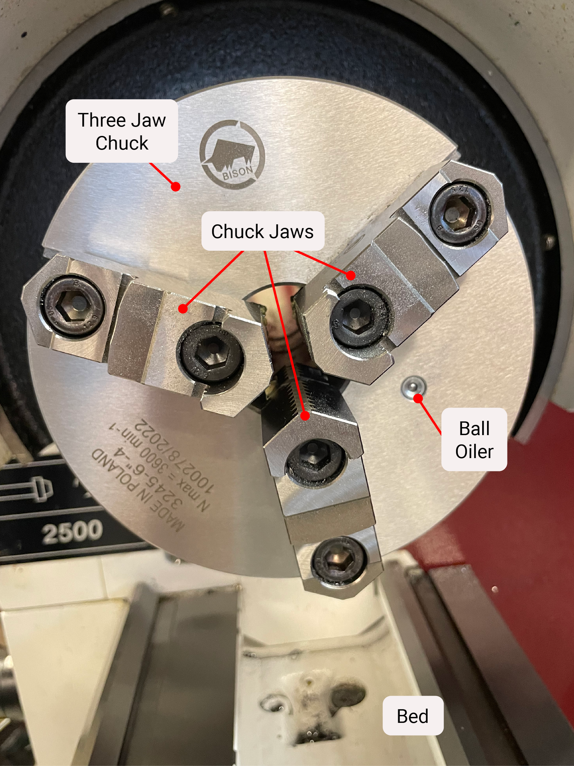
A chuck is a work holding device mounted to the spindle nose of the lathe. One of the most common chucks is the three jaw chuck because of its ease of use. The jaws of the chuck are secured inside of a linear channel. The three jaw chuck is adjusted by a tee handle that is inserted into and turns a square drive shaft. On the inside of the chuck, there is a gear on the end of the square drive shaft. That gear turns a scroll plate that simultaneously moves the three jaws in and out. This style of chuck is capable of gripping on round and hexagonal work. Quality chucks are capable of holding within .003 run out; inexpensive chucks may run out .010-.015 or more.


Four Jaw Chuck
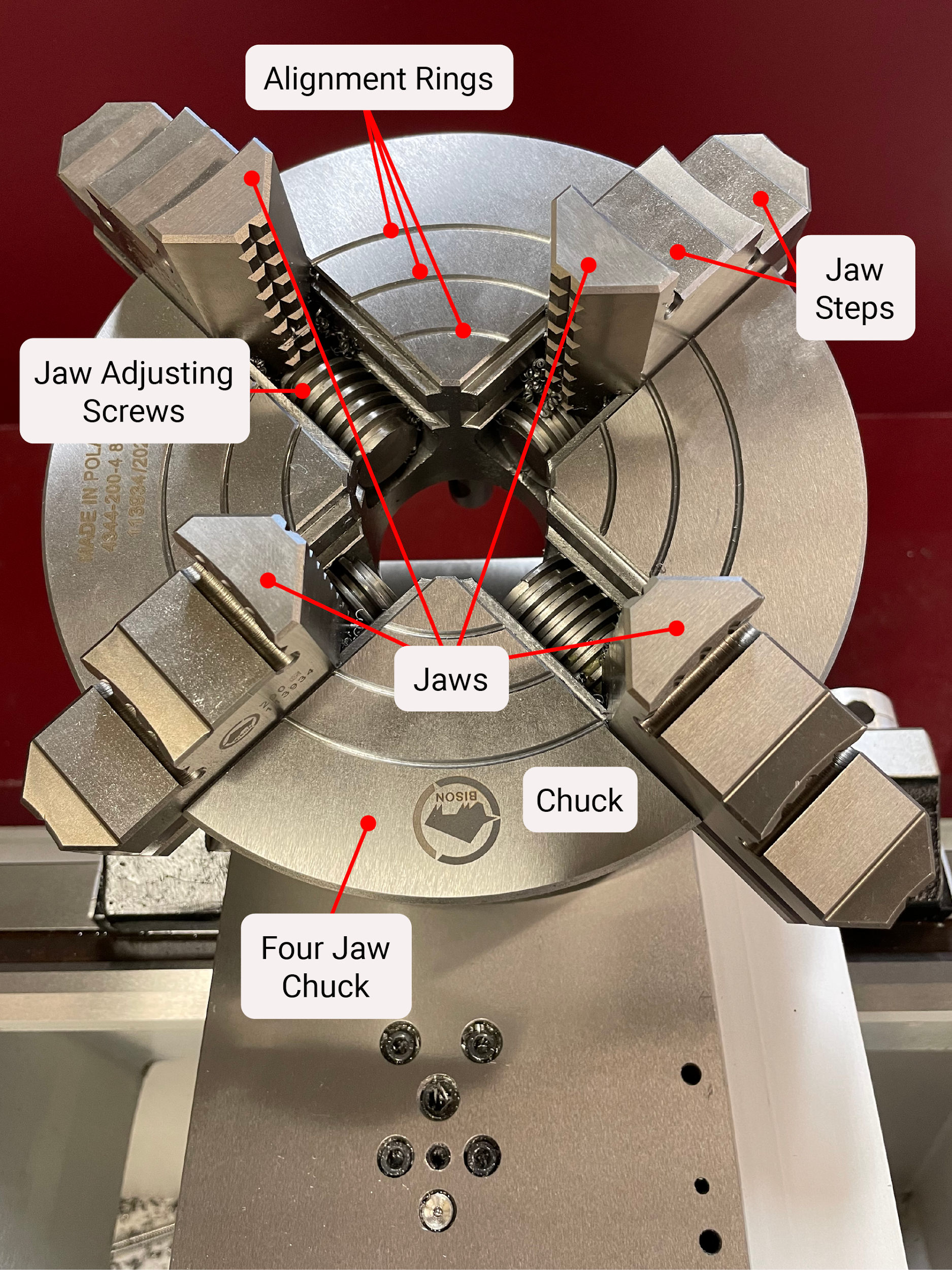
A four jaw chuck is used to hold square or odd shaped parts. It is also used when extra precision is required. The four jaws on this chuck are moved independently of one another, allowing it to have a high degree of adjustability. This adjustability is very useful when a greater level of accuracy is needed than what can be achieved with a three jaw chuck. The four jaw chuck also holds the parts with more stability because there is a jaw every 90 degrees versus every 120 degrees on the three jaw chuck.


Face Plate
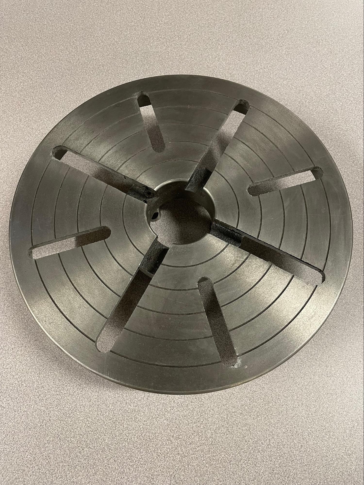
A face plate is another workholding device that is mounted to the spindle nose. It is often used to bolt larger or odd shaped parts to perform turning operations. A faceplate has multiple slots to allow tee nuts and other securing devices to be used for part mounting. A faceplate can be very versatile but also much more cumbersome to set up; therefore, they aren’t as commonly used as chucks.
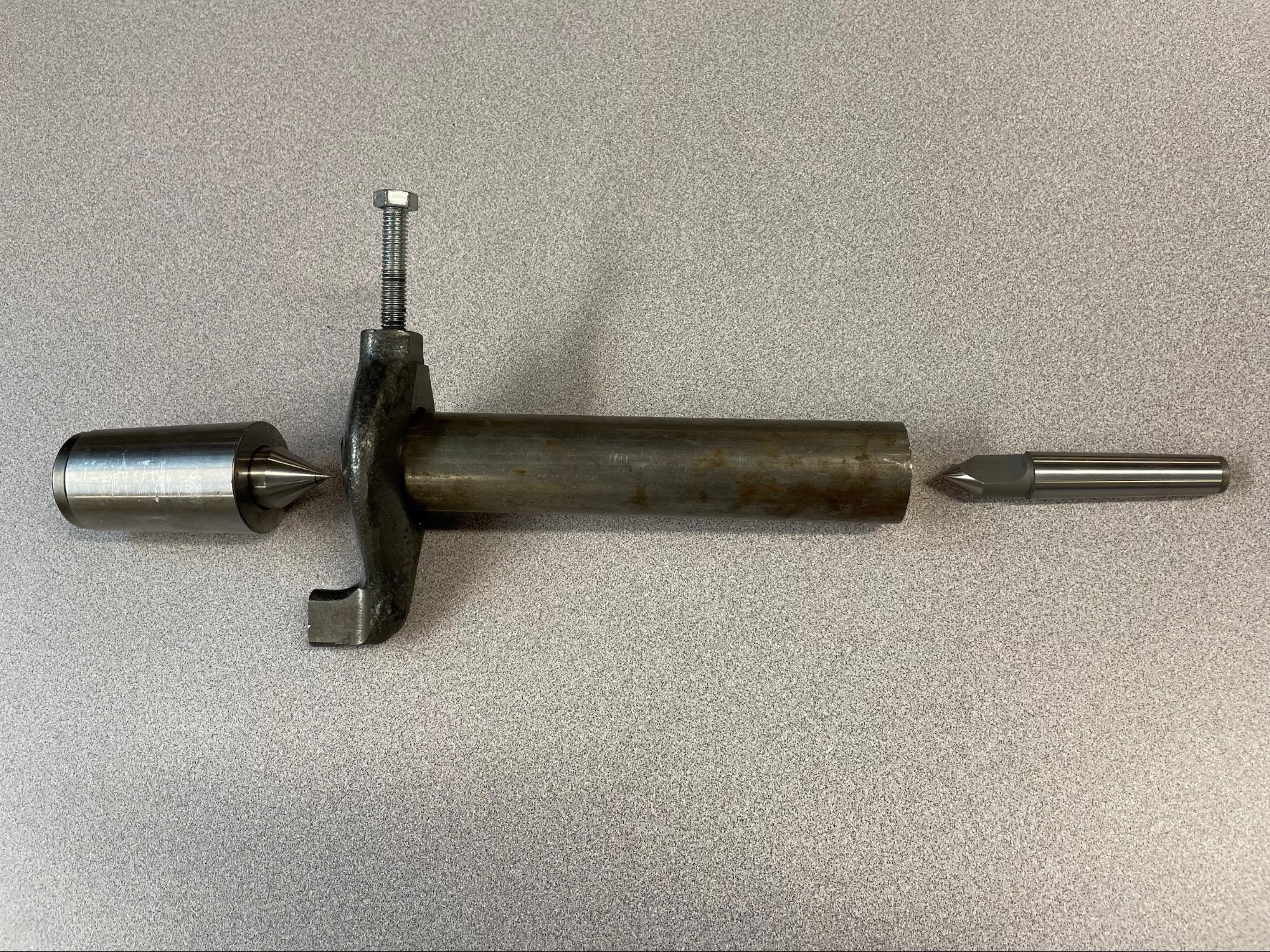
Centers
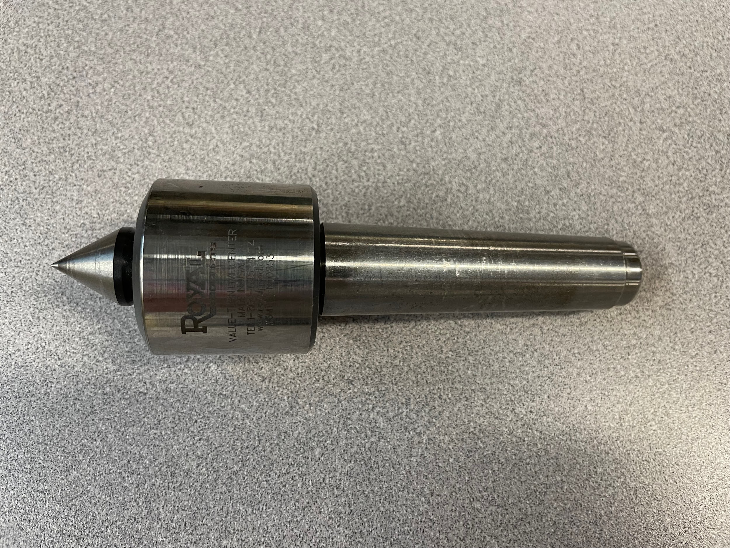
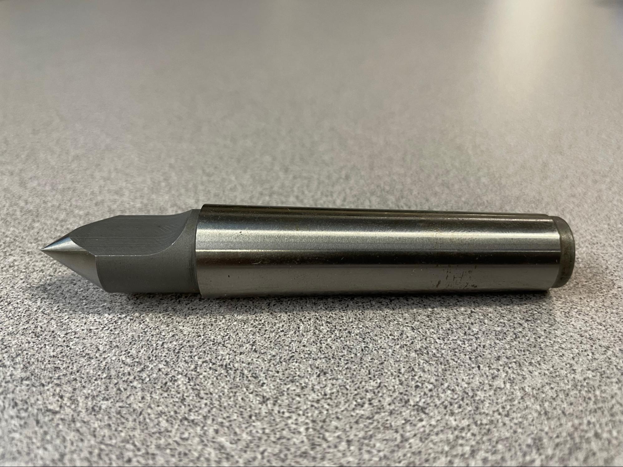

Centers are methods of workholding and support on a lathe. They are identified by their 60 degree point on one end. Often, a center can be found in the tailstock of a lathe, inserted into a center drilled mark of a part, supporting a long, unstable length of work. Sometimes the whole part is held in between centers, one in the spindle and one in the tailstock. Turning between centers is often considered the best method for controlling end to end runout on a part because it takes out the imperfections chucks have. Centers on the spindle end are always solid and rotate with the spindle. Centers in the tailstock can be solid and static. This type of center is called a “dead center.” These centers must be lubricated during use to not damage the center or the part. The more popular center on the tailstock side is called a “live center,” and it has bearings inside that allow the end of the center to rotate with the work. A dead center is technically more accurate because it has no moving components. Its need for lubrication and tendency to run out of lube at high RPMs have made the live center the most common.
Lathe Dog
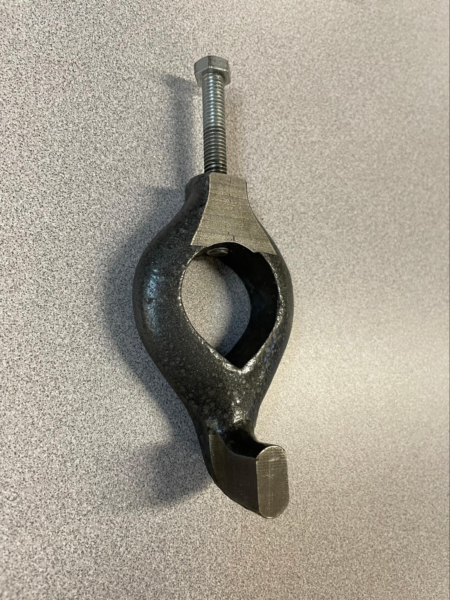
A lathe dog is used as a drive mechanism when parts are to be turned between centers. The lathe dog is generally a ring that bolts to one end of the part with an angled leg that is inserted into the slots in the faceplate or in-between the jaws of a chuck. Extreme caution must be exercised when using a lathe dog because of the odd shaped protrusions rotating around at high speed. These protrusions could grab a careless operator, causing great injury.
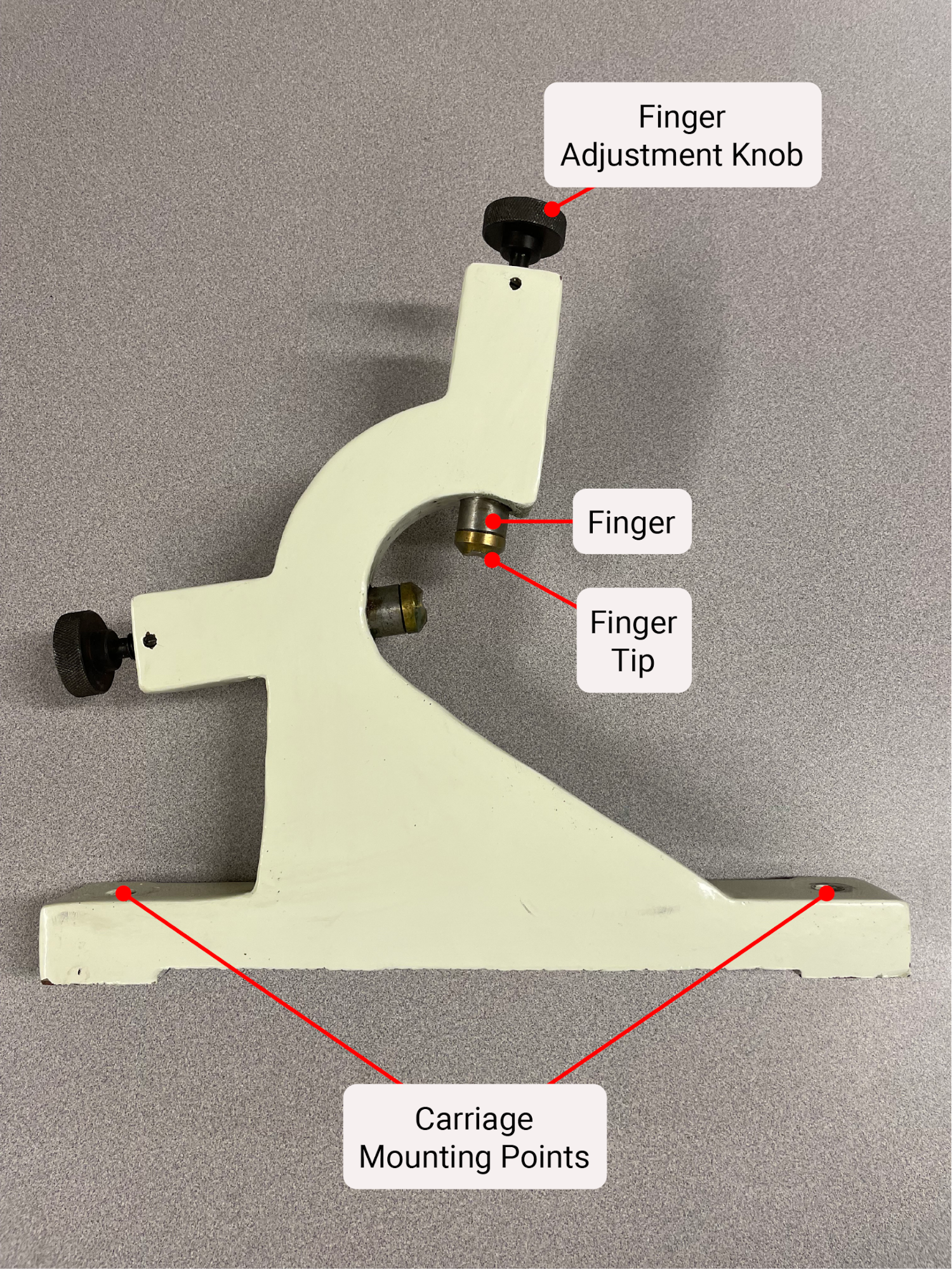
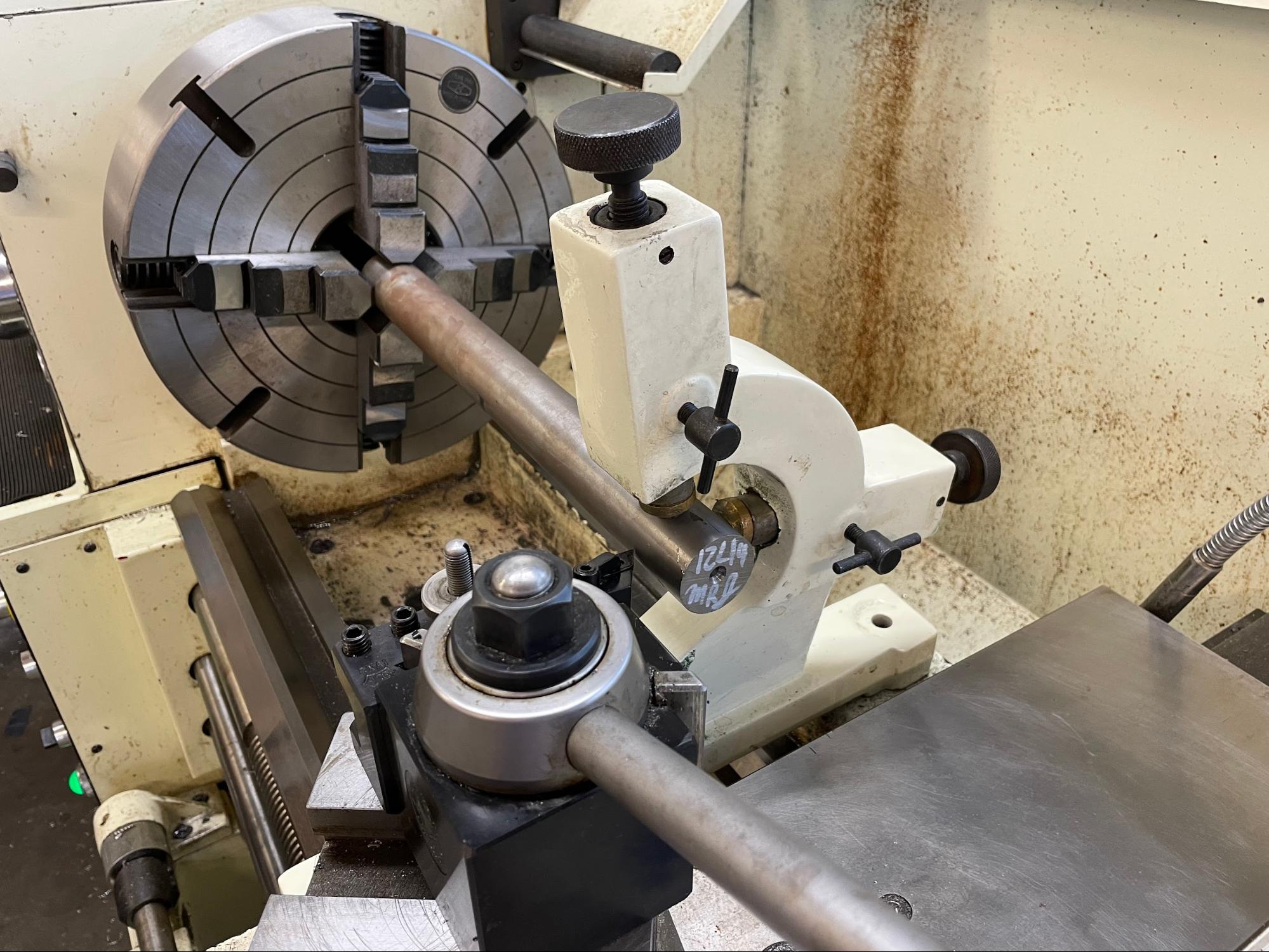
Steady Rest
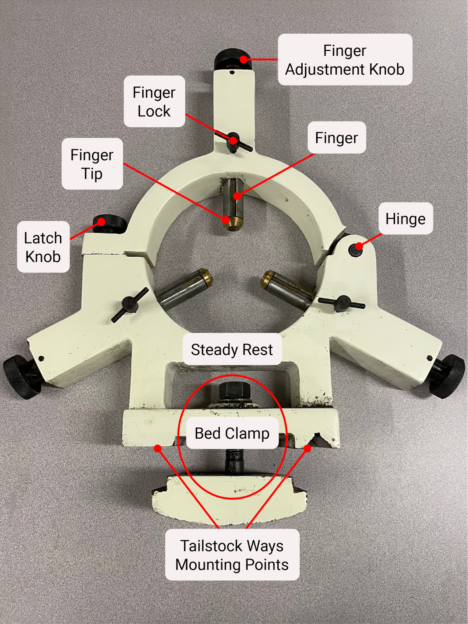
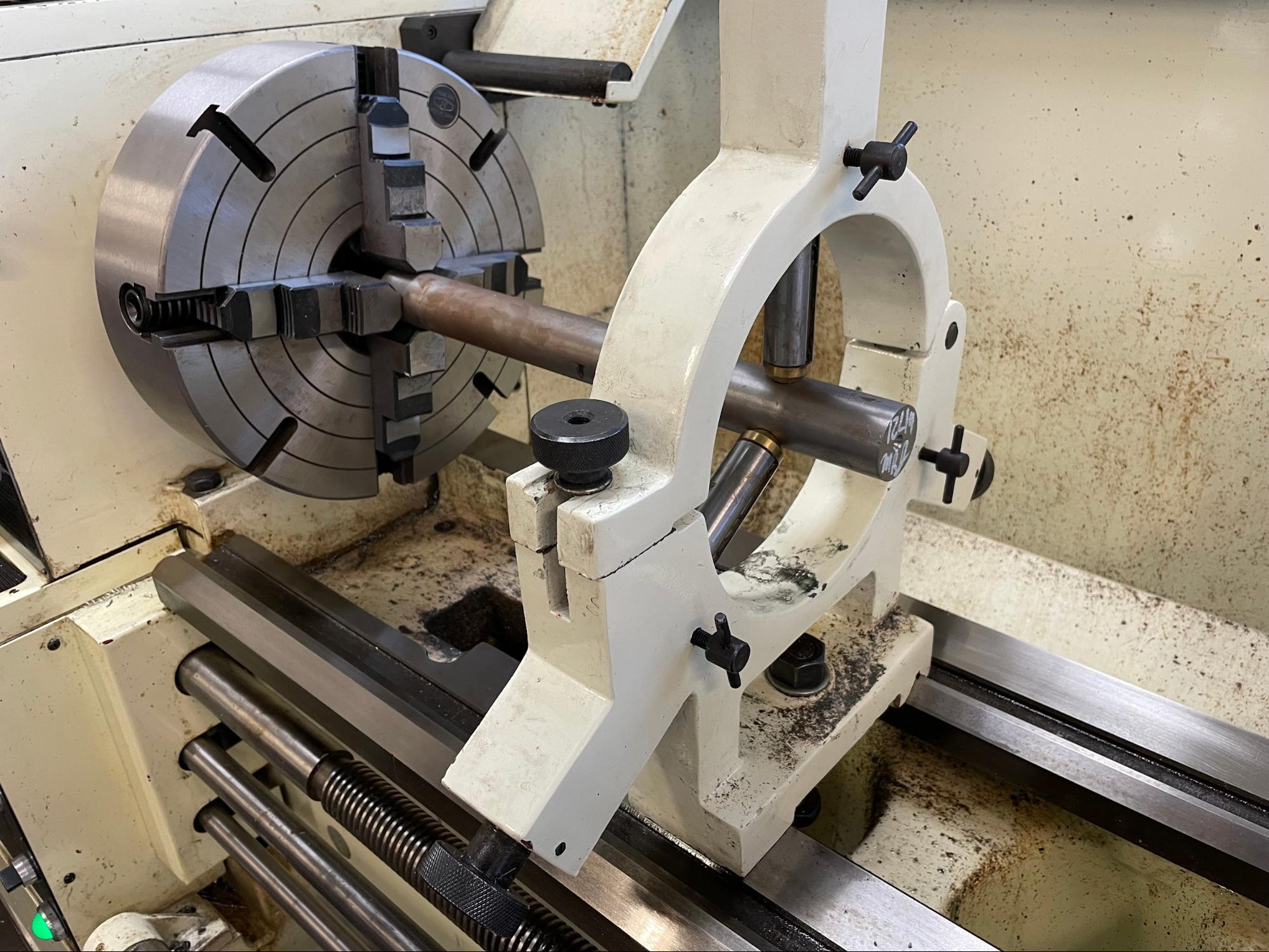
A steady rest is designed to support long work being cut on a lathe. It can be used to support the middle of work that has a tailstock supporting the end, or it can support the end while face machine work is being completed. The device bolts to the ways and has three independently adjustable arms inside a ring that support the revolving work. The top half of the ring is hinged with a latching mechanism to allow for work to be easily loaded and unloaded. The ends of the arms often have bearings for smooth rolling over the outside of the work. Older lathes or less expensive import lathes may have wear pads instead of bearings. These pads need to be well lubricated to keep from wearing out and damaging the work.
Follower Rest
A follower rest is another device used to steady a long part being turned on the lathe. It is used in conjunction with a tailstock to stabilize the part near the cutting action. The follower rest is mounted to the carriage and moves along with it during the cut. This is how it gets its name; it follows the movement of the carriage. The follower rest has two adjustable support arms, similar to the steady rest, but it relies on the cutting tool as the third point of support. In theory, the cutting action will push the part up and away from the cut and into the two support arms of the follower rest. The follower rest is often used for parts that need to be turned along the entire length of a long, thin shaft.
Attributions
- Figure 10.30: 3 Jaw chuck by Micky R. Jennings, courtesy of Wenatchee Valley College, for WA Open ProfTech, © SBCTC, CC BY 4.0
- Video 10.3: Micky R. Jennings, courtesy of Wenatchee Valley College, for WA Open ProfTech, © SBCTC, CC BY 4.0
- Video 10.4: Micky R. Jennings, courtesy of Wenatchee Valley College, for WA Open ProfTech, © SBCTC, CC BY 4.0
- Figure 10.31: 4 Jaw chuck by Micky R. Jennings, courtesy of Wenatchee Valley College, for WA Open ProfTech, © SBCTC, CC BY 4.0
- Video 10.5: Micky R. Jennings, courtesy of Wenatchee Valley College, for WA Open ProfTech, © SBCTC, CC BY 4.0
- Video 10.6: Micky R. Jennings, courtesy of Wenatchee Valley College, for WA Open ProfTech, © SBCTC, CC BY 4.0
- Figure 10.32: Faceplate by Micky R. Jennings, courtesy of Wenatchee Valley College, for WA Open ProfTech, © SBCTC, CC BY 4.0
- Figure 10.33: Live center by Micky R. Jennings, courtesy of Wenatchee Valley College, for WA Open ProfTech, © SBCTC, CC BY 4.0
- Figure 10.34: Dead center by Micky R. Jennings, courtesy of Wenatchee Valley College, for WA Open ProfTech, © SBCTC, CC BY 4.0
- Figure 10.35: Spindle center by Micky R. Jennings, courtesy of Wenatchee Valley College, for WA Open ProfTech, © SBCTC, CC BY 4.0
- Figure 10.36: Lathe dog by Micky R. Jennings, courtesy of Wenatchee Valley College, for WA Open ProfTech, © SBCTC, CC BY 4.0
- Figure 10.37: Work between centers by Micky R. Jennings, courtesy of Wenatchee Valley College, for WA Open ProfTech, © SBCTC, CC BY 4.0
- Figure 10.38: Steady rest by Micky R. Jennings, courtesy of Wenatchee Valley College, for WA Open ProfTech, © SBCTC, CC BY 4.0
- Figure 10.39: Steady rest in use by Micky R. Jennings, courtesy of Wenatchee Valley College, for WA Open ProfTech, © SBCTC, CC BY 4.0
- Figure 10.40: Follower rest by Micky R. Jennings, courtesy of Wenatchee Valley College, for WA Open ProfTech, © SBCTC, CC BY 4.0
- Figure 10.41: Follower rest in use by Micky R. Jennings, courtesy of Wenatchee Valley College, for WA Open ProfTech, © SBCTC, CC BY 4.0
A work holding device that uses three simultaneously moving jaws to grip material.
A work holding device that uses four independently moving jaws to grip material.
A flat plate installed on the spindle nose for holding nontraditional shaped work.
A device that is used to support work on the rotational axis.
A device that is bolted to work held between centers in order to transmit rotational force.
A support component that is used to hold the outside of the work when turning long flexible workpieces.
A support component that is used to brace the outside of the work at the point of tool contact when turning long flexible workpieces.
