11.1 Common Surface Grinders
Tim A. Bacon
A grinder is a machine that removes material from a workpiece through the use of an abrasive grinding wheel. Grinders are used to achieve high precision, surface finish, and the overall shape of a workpiece that cannot be achieved through other machining processes like turning, milling, or drilling.
There are different types of grinders used in machining, each designed for a specific purpose. The main three types are horizontal, vertical, and cylindrical grinders.
Horizontal
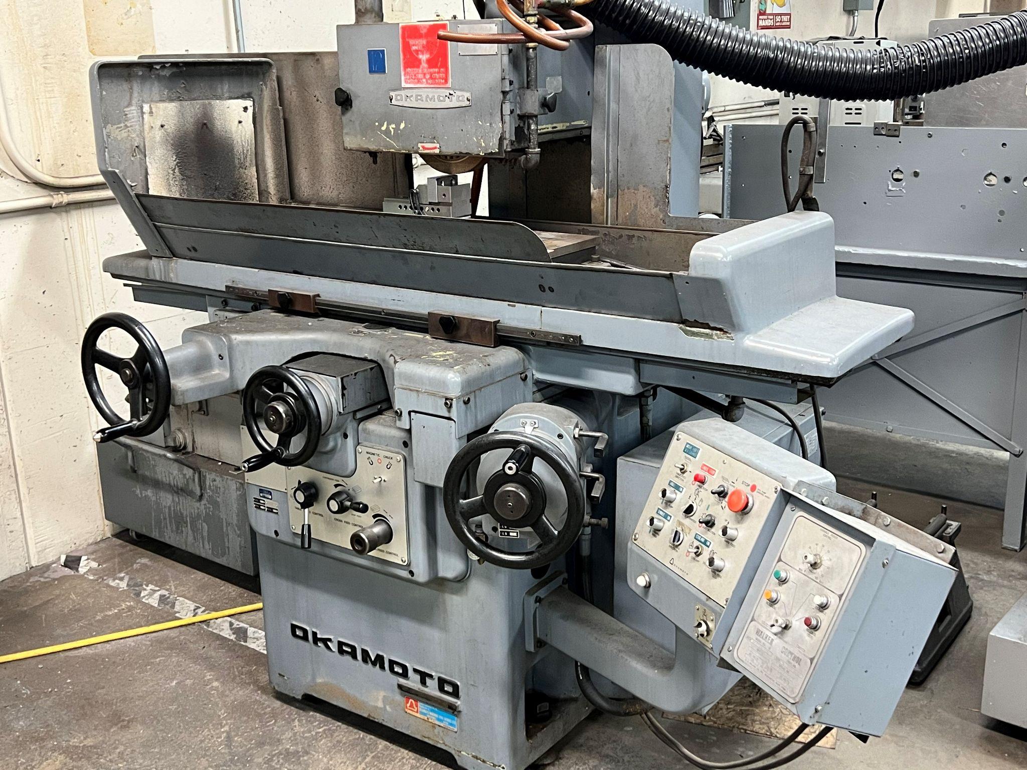
Horizontal spindle surface grinders typically use the outside diameter (OD) of the solid wheel to grind the part surface, as seen in the picture at the start of the chapter.
The most common type of grinding machine is the horizontal spindle with a reciprocating table. The “head” of the machine holds the grinding wheel while it spins. It is moved up and down in a direction perpendicular to the table. This is also referred to as the Z axis. The hand wheel of the head controls the movement in the Z axis. The amount of movement per gradation, or line on the dial, is typically .0001. This is called a “tenth” by a machinist.
Visualize the axis in the image above on the horizontal grinder. The X positive is to the right, Y positive is up away from the part, and the Z positive movement is towards the machinist. The X is workspeed, the Y is in-feed, and the Z is the crossfeed.
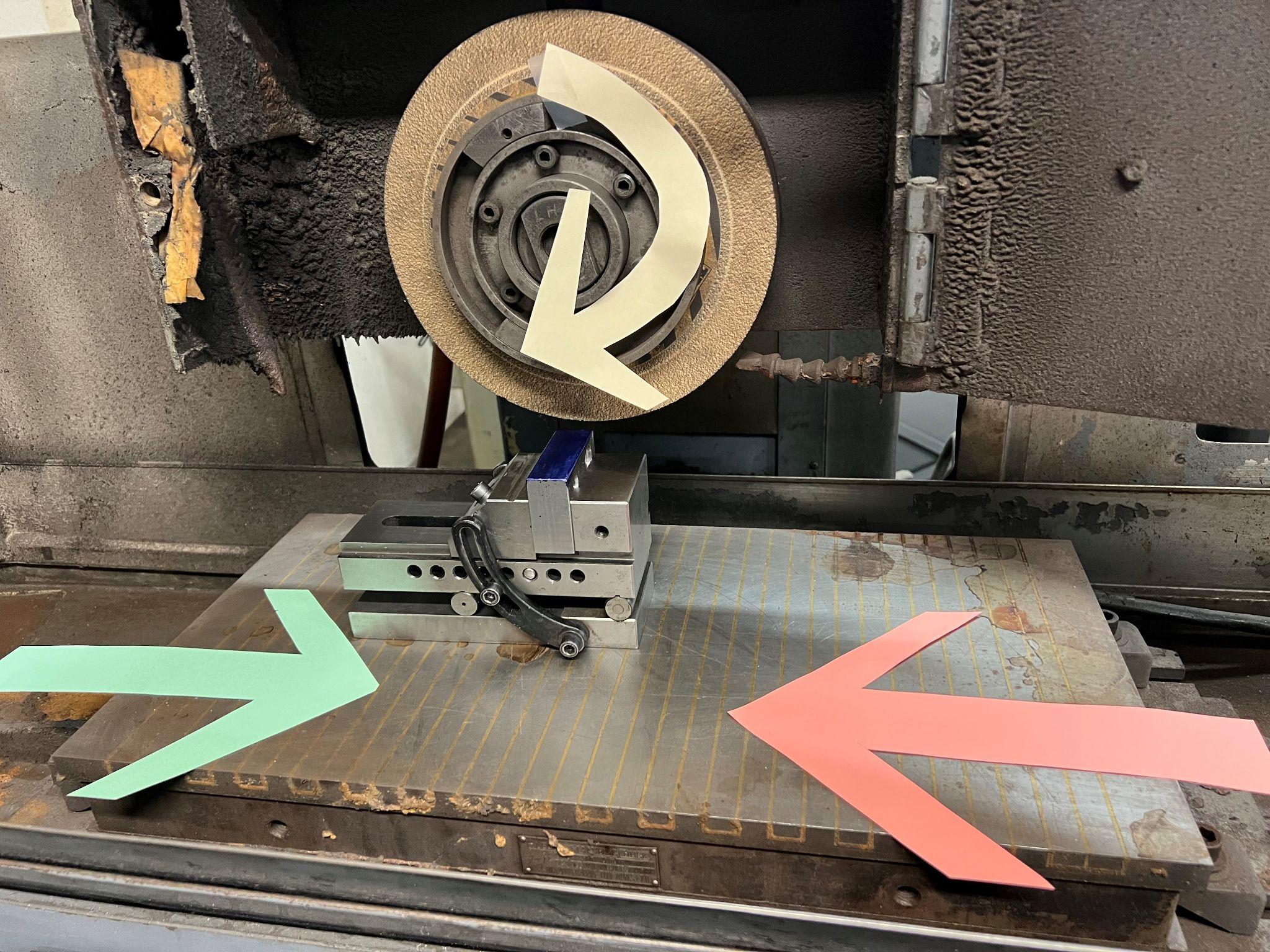
The part will travel back and forth along the long dimension of the table, the X axis, and the short dimension of the table, the Y axis. The X axis is the “work speed” direction, and the Y axis is the “cross feed” direction. The wheel will spin in a clockwise rotation. The right side of the wheel is the ingoing nip that will pull the part in. The left side of the wheel is the outgoing nip that pushes the part away. Passing a part under the grinding wheel from right to left is similar to making a climb cut on a manual mill. Similarly, moving from left to right is a conventional cut on a manual mill.
Critical Safety Note
Never walk or stand on the left side of the grinder when the grinder is being used. The left side of the surface grinder is where parts are ejected if they come loose.
Vertical
Machines with a rotary table will rotate the work beneath the grinding wheel.
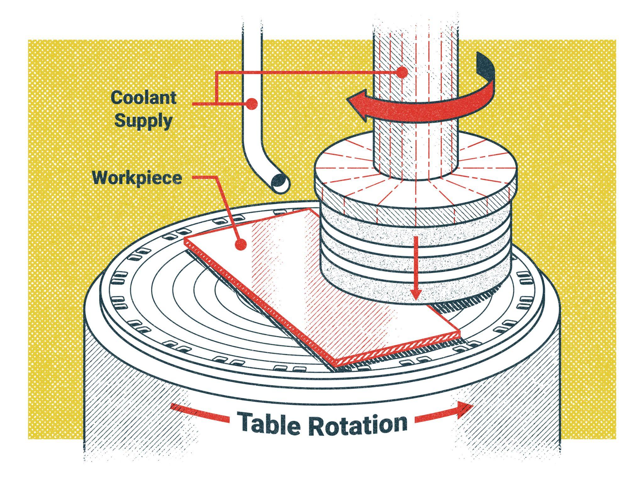
Pictured above is a vertical grinder performing a Blanchard operation where the part can rotate independently from the grinder.
Machines with reciprocating tables move the work back and forth beneath the wheel.
The grinding is done on the side of the wheel. This is also referred to as Blanchard grinding.
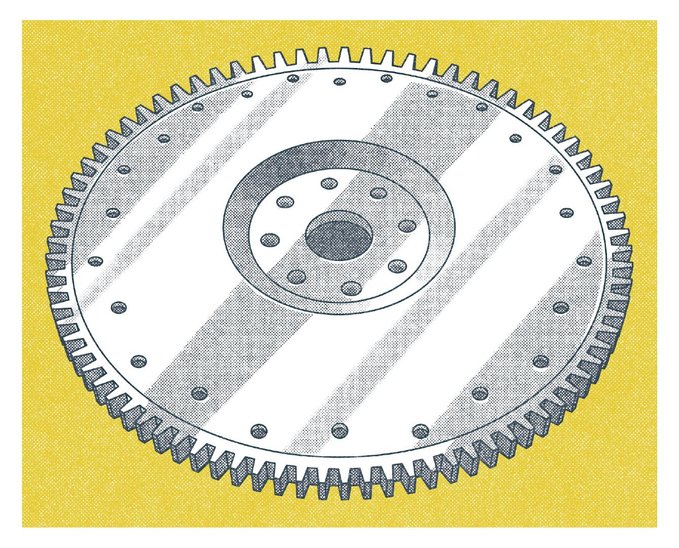
Vertical spindle grinders typically use the side of the grinding wheel to grind the workpiece. The wheel may be solid, or cup shaped. The tables will either be reciprocating or rotary in motion, just like the horizontal grinder. Vertical surface grinders are also referred to as Blanchard grinders. These grinders are mainly used for large, flat plates. In the automotive industry, large flywheels will be Blanchard ground for proper clutch assembly.
Vertical surface grinders will remove substantial amounts of material quickly and efficiently due to the large surface area of the wheel being engaged. Blanchard grinding can also result in a cross hatched pattern on the surface finish. Cross hatching is cosmetically desirable and provides improved wear characteristics where two parts have movement between them.
Cylindrical
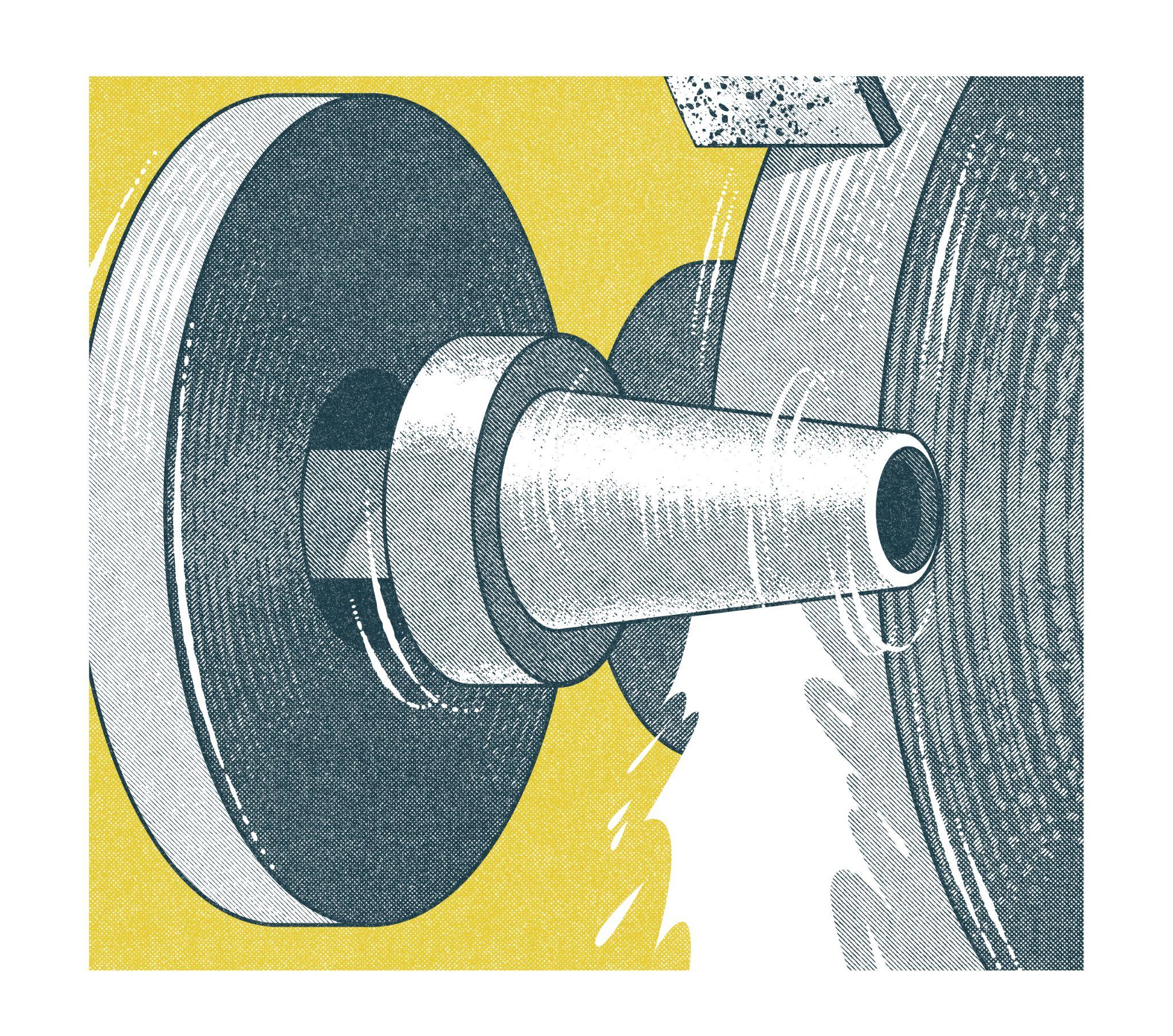
The picture above shows an operation on a cylindrical grinder.
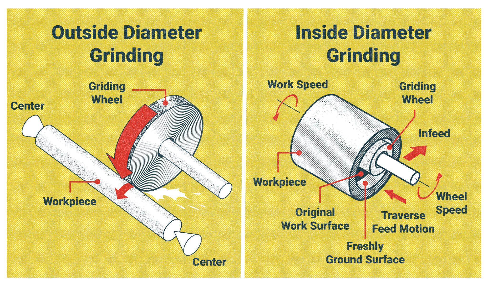
Cylindrical grinders can be either external (a), or internal (b).
Cylindrical grinders are used to grind diameters, shoulders, and faces much like the features that are cut on a lathe. The workpiece is rotated against the surface of the grinding wheel as it turns. A hand wheel is used to make precise movements of the wheel head to set the cut depth. A power table moves the grinding wheel along the axis of the part’s rotation.
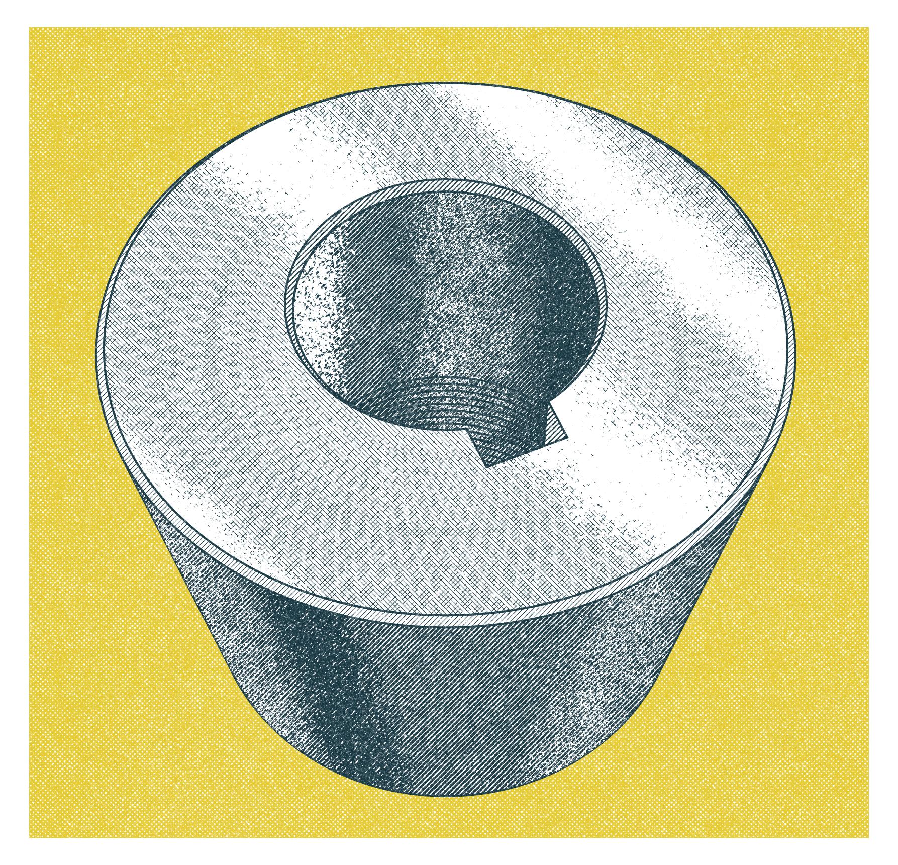
If a grinder is configured to cut only the outside diameter of the part, the OD, it is referred to as an OD Grinder. The same can be said for a machine set up to grind internal diameters, or ID. Faces and shoulders can also be ground with the side of the wheel on either style of machine mentioned previously. An ID grinder uses a wheel mounted on an arbor. The arbor is a shaft that supports the grinding wheel as it removes material in a cylindrical shape inside a part.
Attributions
- Figure 11.1: Horizontal surface grinder by T Bacon, courtesy Bates Technical College, for WA Open ProfTech, © SBCTC, CC BY 4.0
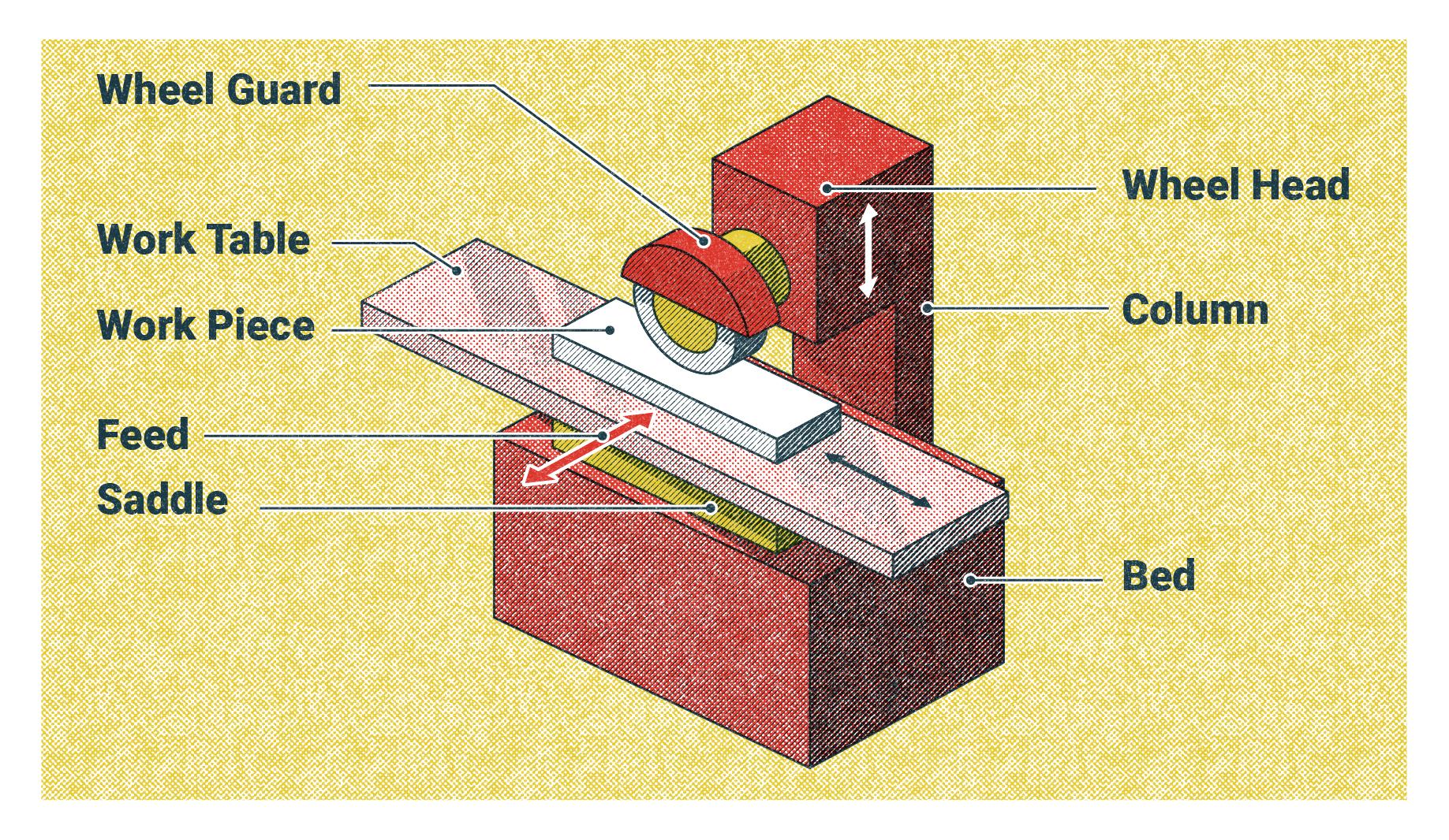
- Figure 11.2: Main parts of a surface grinder by Nicholas Malara, for WA Open ProfTech, © SBCTC, CC BY 4.0
- Figure 11.3: Directions by T Bacon, courtesy of Bates Technical College, for WA Open ProfTech, © SBCTC, CC BY 4.0
- Figure 11.4: Blanchard grinding by Nicholas Malara, for WA Open ProfTech, © SBCTC, CC BY 4.0
- Figure 11.5: Flywheel by Nicholas Malara, for WA Open ProfTech, © SBCTC, CC BY 4.0
- Figure 11.6: Cross hatch texture on surface by Nicholas Malara, for WA Open ProfTech, © SBCTC, CC BY 4.0
- Figure 11.7: Cylindrical grinding by Nicholas Malara, for WA Open ProfTech, © SBCTC, CC BY 4.0
- Figure 11.8: Cylindrical grinding by Nicholas Malara, for WA Open ProfTech, © SBCTC, CC BY 4.0
A scale or series of lines representing the change in dimension.
The speed at which the grinding wheel passes over a workpiece traveling left to right along the X axis.
The movement of the grinding wheel being lowered into the material to make a cut along the Y axis.
The short movement in and out along the Z axis.
A pinch point where the grinding wheel is near the material. The “in” side will pull anything into it.
A pinch point where the grinding wheel is near the material. The “out” side will push anything away from it.
A rotary table is a mechanical device designed to rotate a workpiece around a vertical axis. A vise can be mounted on top of the table to allow for circular, and angled cuts.
Grinding with a rotating magnetic table to remove large amounts of material from a surface.
A surface grinding machine that moves the workpiece back and forth beneath the grinding wheel.
Please look for related terms in the Glossary
The resulting surface finish where two sets of parallel lines intersect.
Outside diameter
inside diameter
The shaft that the grinding wheel mounts on.
