3.2 Sheet Size and Format
D.M. Donner
The Sheet
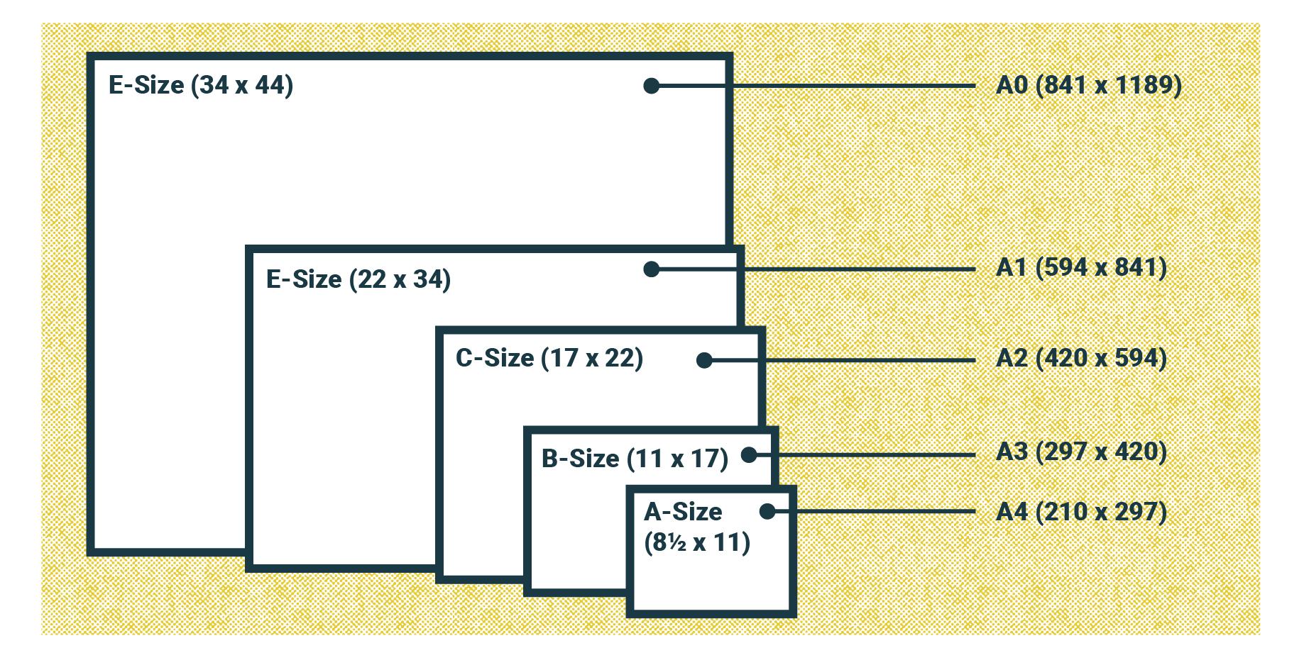
The physical size of the drawing sheet is based on the A size which is 8.5 X 11″ (standard copy paper), and subsequent sizes are multiples of this. Size B is 11 X 17″, Size C is 17 X 22″, Size D is 22 X 34″, Size E is 34 X 44″ and size F is 28 X 40″. Since these are all scaled in inches, they are the ANSI standard.
Drawing margins have minimal standards of 0.50″ and engineers may modify them as they see fit.
For the machinist, the larger the sheet size, the easier it is to extract details. If you are fortunate to have a computer at your workstation, you may open the sheet and zoom in to arrive at any detail you desire. An advantage of the printed sheet is the ability to mark up the sheet with any helpful annotations.
Title Block
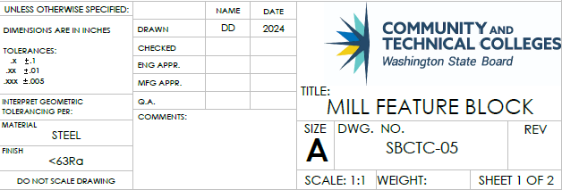
The title block is a section of a drawing that has information that pertains to the entire set of drawings. In the case of multiple pages drawings, the title block must be used on page one and may be used on the following pages. Title blocks are important because they explain how to interpret information found in the drawing area. Most companies adopt a best practice to define how they will use the title block within their organization. Best practices are procedures agreed upon within an organization to standardize information, also referred to as standard operating procedures. This explains why you will find subtle differences in prints and title blocks used by engineers. The ASME standards set forth the following guidance for title blocks (2013a, Section 6).
Information found in a title block includes company name, title of the drawing, the drawing number, revision number, date of drawing, scale of drawing, the sheet number if multiple sheets are used, tolerance information, materials used, surface finish, projection view used, and comments.
Drawing Area
All of the information you will need is found in two places on a drawing: the drawing area and the title block, so these two topics deserve special attention.
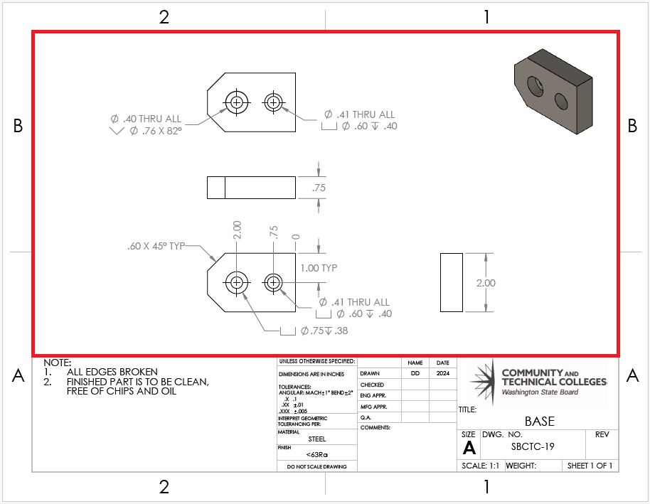
The drawing area (illustrated within the red block above) refers to the designated area within the drawing sheet where the graphical representation of the component, part, or assembly is created. It’s the space where the actual visual and geometric details of the object being documented are illustrated using lines, dimensions, symbols, annotations, and other graphical elements.
The drawing area is critical because it serves as the primary visual representation of the engineering design. It allows engineers, manufacturers, and other stakeholders to interpret the design intent, dimensions, and specifications necessary for the construction or fabrication of the component or assembly.
Attributions
- Figure 3.2: Sheet sizes from A through E by Nicholas Malara, for WA Open ProfTech, © SBCTC, CC BY 4.0
- Figure 3.3: Title block by Damon Donner, for WA Open ProfTech, © SBCTC, CC BY 4.0
- Figure 3.4: Drawing space by Damon Donner, for WA Open ProfTech, © SBCTC, CC BY 4.0
a section of a drawing that has information that pertains to the entire set of drawings
Best practices are procedures agreed upon within an organization to standardize information, also referred to as standard operating procedures
the designated area within the drawing sheet where the graphical representation of the component, part, or assembly is created.
