3.5 Dimensions, Tolerance, and Allowance
D.M. Donner
As a machinist, you will spend the majority of your day measuring, calculating, and verifying dimensions from a print. Using the proper equipment to obtain measurements and then comparing them to the engineer’s drawing is an important part of what we do. Here we will focus on obtaining dimensions from a print and determining what the tolerance is for the measured feature.

A tolerance is the accepted amount of variation between the measured dimensions of a part and the nominal dimensions from the print. The center area of a dart board is called a bull’s eye. Any dart that lands within the bull’s eye will score points. Think of tolerance as a bull’s eye that is allowed to change size. If a part tolerance can vary by a greater amount, the bull’s eye can be larger, and any measurement that falls within that tolerance is acceptable. If the engineer requires a tighter tolerance for a dimension, the bull’s eye will be smaller, allowing less variance; however, any dimension that falls inside the tolerance is acceptable.
You may hear tolerance and allowance used interchangeably, but in fact, they are different. An allowance is the engineered difference from nominal, which allows parts to function as necessary. If a slip fit needs to exist between a shaft and a hole, the engineer will use an allowance of .01″ between the two part dimensions. In order to ensure the allowance is met, the engineer may allow a .005″ tolerance to the nominal dimensions.
A nominal dimension refers to the standard or intended size, value, or dimension of a component or part without considering variations or deviations that may occur due to manufacturing processes or other factors. It represents the theoretical or target value used as a reference point for design, analysis, and communication in technical specifications.
In simpler terms, the nominal value is the ideal or planned measurement, size, or characteristic that a part or feature is expected to have according to the design or specification. However, due to inherent variability in manufacturing processes and other factors, the actual measured values may deviate slightly from this nominal value. These deviations are taken into account using tolerances and allowances to ensure that the manufactured part is still within an acceptable range of functionality and performance.
All manufactured parts have inherent variations caused by many factors, such as work holding, tool holding, tool wear, human interaction with the system, temperature, and stock variations, just to name a few. There is no such thing as the perfect part. It is vital that you understand this principle because many hours can be wasted chasing this impossible standard. The machinist does not operate in the perfect world, but we do exist in the realm of allowed variation. The engineers who design the parts we make also understand this principle, and they design this variation into the part.
Overall Dimensions (OD)
Overall dimensions are the primary dimensions that define the overall size of the part in terms of length, width, and depth.
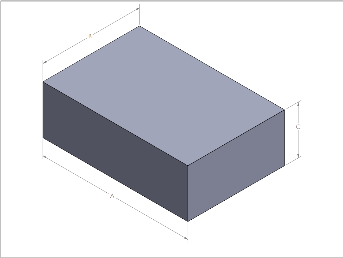
Dimensions that define the height, width, and depth of features or components provide important size information. Think of the overall dimensions as the smallest box in which the part will fit. This image becomes useful when a machinist must determine the stock size necessary to make a part.
The English language gives us many words to identify a dimension. Some of these terms are thick, tall, wide, deep, long, and short. How would you define how tall a part is? Which dimension would you apply “tall” to? When people use different vocabulary, things can get confusing. For this reason, standard terms such as length, width, and depth are used to define the overall size of an object if it is not cylindrical. Cylindrical objects are measured in diameter and length.
Which side of the part gets which label? The figure above of a 1-2-3 block has labels on three sides. In this example. A defines length, B defines width, and C defines depth. Almost all parts have length, width, and depth, so they must be defined on a drawing. In practice, machinists are referencing a specific dimension on a print, and the feature it measures is illustrated for us. Our job is to understand what the feature is and then utilize measuring equipment to ensure it is within tolerance.
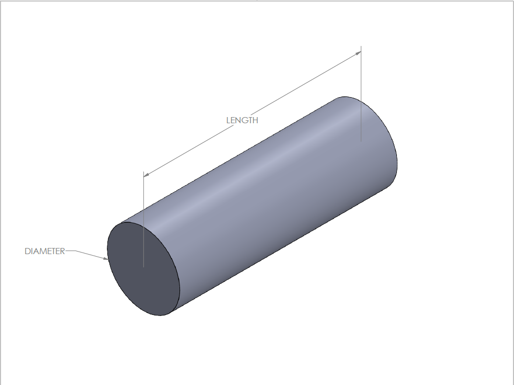
Items that do not have all three overall dimensions will be cylindrical parts where diameter replaces width and depth. This is due to symmetry, where the diameter measures the same as width and depth.
Overall dimensions are linear dimensions that reference some sort of datum. In engineering and drafting, a datum is a reference point, surface, or axis on an object against which measurements are made.
Diameter (Ø) Dimensions
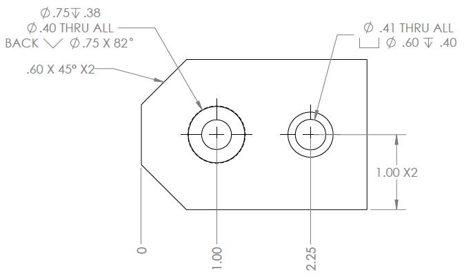
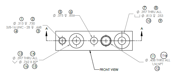
Diameter dimensions are critical for circular features such as holes, shafts, and other cylindrical parts. The above drawing has several diameter callouts including measurements for counterbores, thru holes, and countersink features. It is not uncommon for lathe operators to refer to these outside diameter dimensions as OD dimensions.
Radial Dimensions
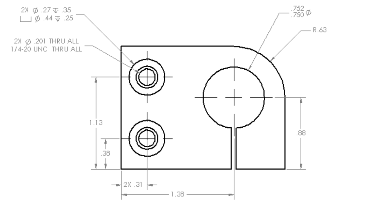
Radial dimensions define the distance from the center of a circular feature to a point on its periphery, often used for holes or circular cutouts. Radius callouts are used on arc type features, which do not constitute a full radius or circle. As simple as radius and diameter seem, they are two of the most confusing dimensions used.
Angular Dimensions
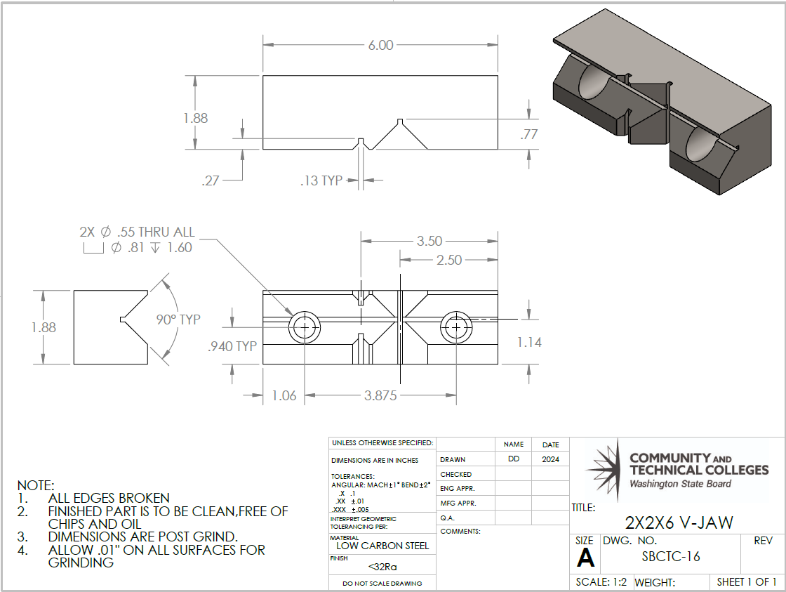
Angular dimensions define the angle between two lines or surfaces, and these measurements are crucial for specifying orientations and alignments. For example, angular dimensions are used to define the angle needed for a fastener to sit in a countersink. In the drawing above, the deep V-cut on the vise jaws is defined as 90° with the added note of “TYP”. TYP means typical, and this note tells the machinist that the measurement can be applied to similar areas on the print. Instead of TYP, the engineer could have used “3X” to specify that the 90° appeared in three places on this drawing.
Center-to-Center Dimensions
Center-to-center dimensions define the distance between the centers of two features which are often used for holes, screws, or bolts. In the drawing above, the distance between the counterbores used to mount the jaw to a vise are called out as a center-to-center dimension.

Chamfer Dimensions
A chamfer is a sloped or angled edge between two connecting surfaces of a part. It can be used on either an internal or external edge. Dimensions specify the size and type of chamfers on a part and usually reference an angle and length. The above part has a 45° angle measuring .60″ in length.
Hole Patterns and Spacing Dimensions
These dimensions define the arrangement and spacing of holes in a part, often specifying the distances between holes. Hole patterns or bolt hole circles (BHC) are centered on a specified diameter with a number of holes evenly spaced along it.
Counterbore Dimension (⌴)
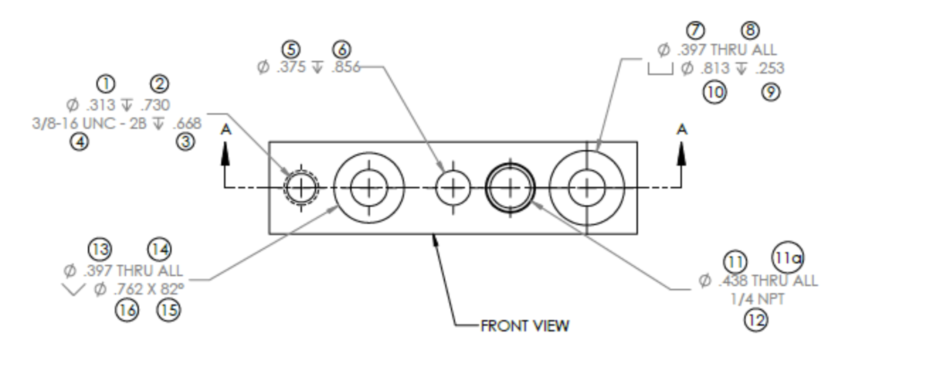
A counterbore is a blind hole, one that does not go through the part completely. A counterbore has a depth and diameter designed to house the head of a fastener so that it sits flush with the part. The counterbore symbol (⌴) needs both a depth, and a diameter (⌀) measurement to establish its features. The depth of the counterbore is prefaced with a symbol that looks like a “T” with an arrow at its base. Since the counterbore is created to house a fastener, there will also be a thru-hole diameter called out. In the figure above, DIM tags 7 through 10 define a counterbore feature.
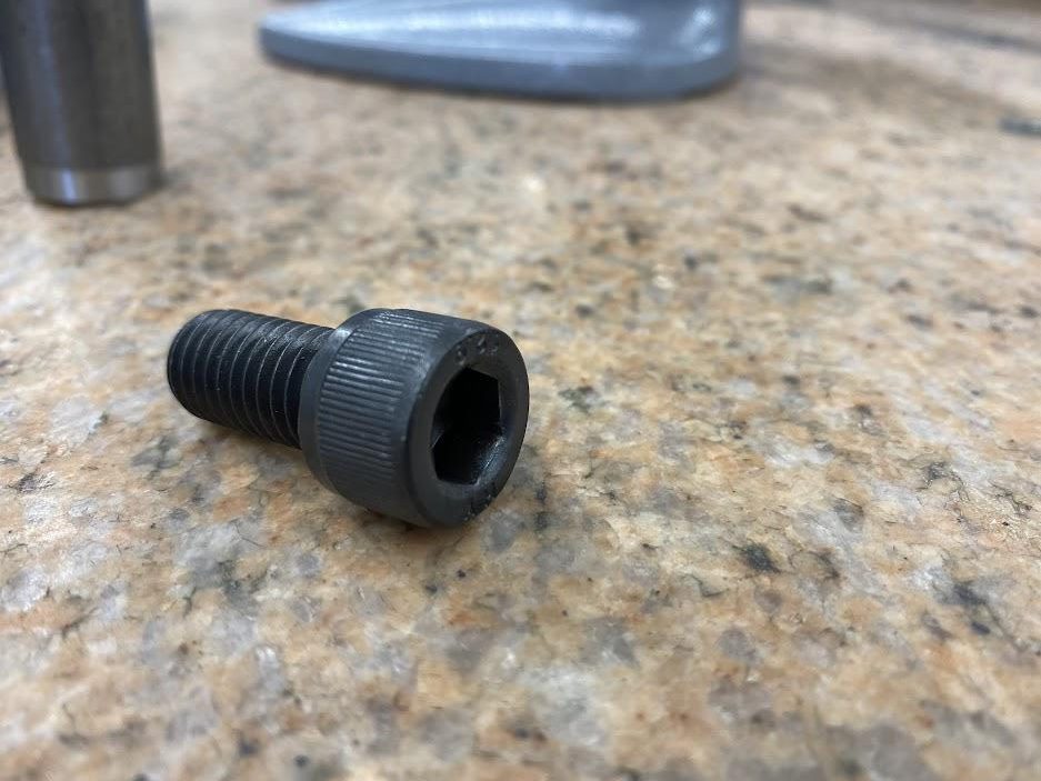
The above socket head cap screw (SHCS) is used extensively in many industries and is a common feature in many parts made by machinists. There are a few similarly headed screws, such as the button head cap screw (BHCS), which has a lower profile, but the SHCS is most common.
Countersink Dimension (⌵)
A countersink is a hole feature that allows a flathead screw to sit flush with the face of a part.
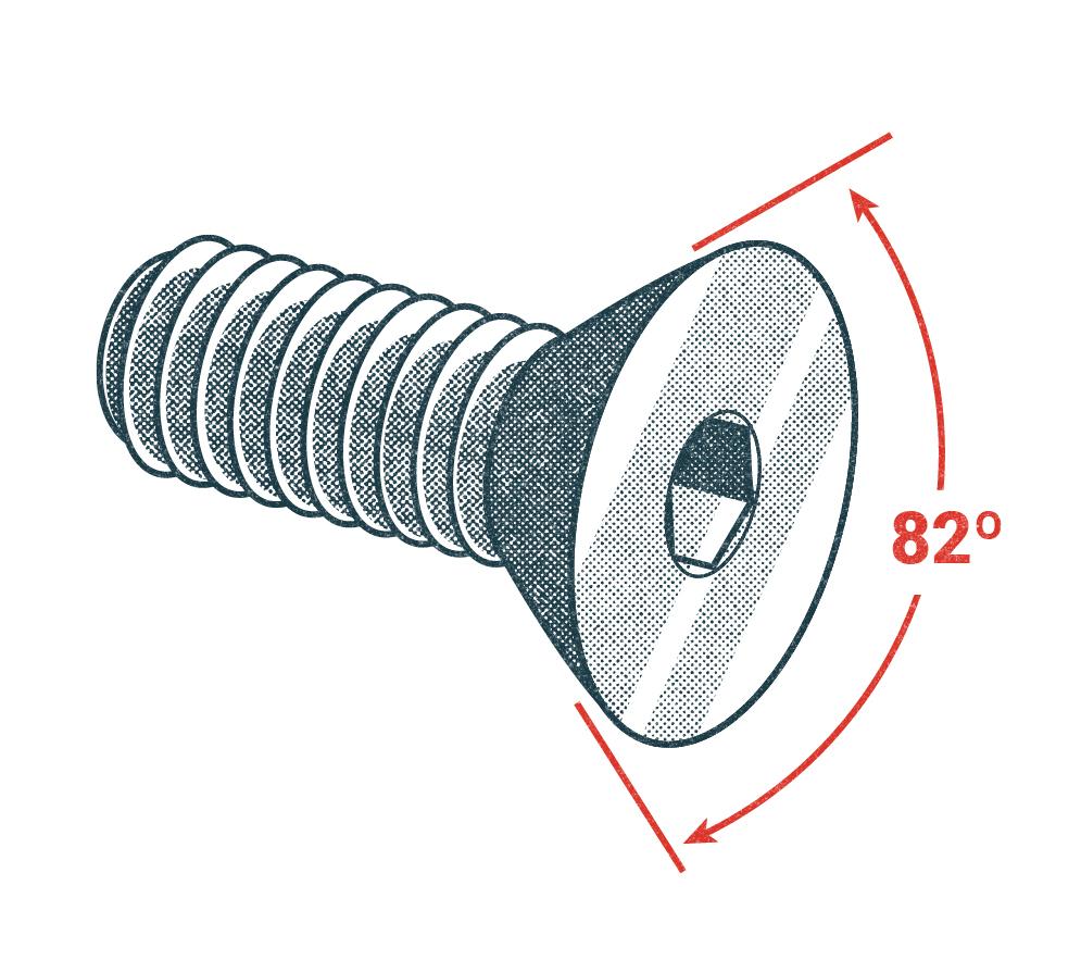
Flathead screw
Inch flathead screws have an 82° angled head, and metric use 90° angle heads. There are some aviation applications where 100° flathead screws are used, but the most common hardware is 82°. This hole callout feature requires the angle and diameter to be specified. Measuring these features requires a chamfer gage or optical comparator. Verifying the angle is just a matter of measuring the tool used to make the feature. In the figure above, DIM tags 13 through 17 define a feature with a countersink.
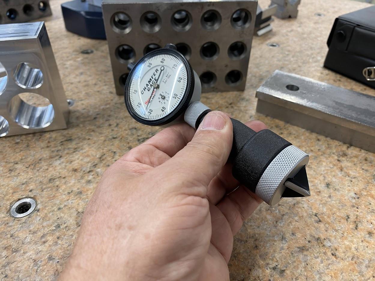
A special piece of inspection equipment can be used to take diameter readings on countersinks to ensure the diameter is within tolerance (more on this in Chapter 4, Metrology).
Threaded Hole Callout
A threaded hole callout presents the hole feature information using a series of symbols, numbers, and text that you must decipher. Threaded hole callouts must list the following information:
- Thread series (Inch, metric)
- UNC (Unified National Coarse)
- UNF (Unified National Fine)
- Metric (M)Pitch (how far the fastener advances in one revolution)
- Major diameter (½’, ⅜”, ¼”…)
- Class of fit (2A, 2B…)
- Tap Drill diameter and end condition (thru or depth).
- Thread end condition (thru or depth).
In the figure above, DIM tags 1 through 4 define a threaded feature. The feature is a blind ⅜-16 UNC 2B threaded hole. DIM tag 1 defines the tap drill size used for the thread (.313″). This is a 5/16″ (.3125″) drill expressed in three decimal places. DIM tag 2 defines the depth of the tap drill hole at .730″. It is important to note that this is the depth of the full diameter, not the depth to the drill tip, since the conical drill tip portion of the hole is unusable for threads. DIM tag 4 states the actual thread to be cut into the drilled hole; ⅜-16 UNC – 2B. Lastly, the end condition of the threads is .668″ depth. The depth symbol is in the shape of a capital T with a V at the bottom. This depth symbol will be used on all features that do not pass through the part.
Attributions
- Figure 3.19: Darts by Richard Matthews is released under CC BY 2.0
- Figure 3.20: Overall dimensions by Damon Donner, for WA Open ProfTech, © SBCTC, CC BY 4.0
- Figure 3.21: Cylindrical shape by Damon Donner, for WA Open ProfTech, © SBCTC, CC BY 4.0
- Figure 3.22: Diameter dimensions by Damon Donner, for WA Open ProfTech, © SBCTC, CC BY 4.0
- Figure 3.23: The radius of the rounded corner by Damon Donner, for WA Open ProfTech, © SBCTC, CC BY 4.0
- Figure 3.24: Angular dimensions by Damon Donner, for WA Open ProfTech, © SBCTC, CC BY 4.0
- Figure 3.25: The chamfered corner of the base part by Damon Donner, for WA Open ProfTech, © SBCTC, CC BY 4.0
- Figure 3.26: Hole callouts by Damon Donner, for WA Open ProfTech, © SBCTC, CC BY 4.0
- Figure 3.27: Socket head cap screw by Damon Donner, for WA Open ProfTech, © SBCTC, CC BY 4.0
- Figure 3.28: Flathead screw by Nicholas Malara, for WA Open ProfTech, © SBCTC, CC BY 4.0
- Figure 3.29: Chamfer gage used for measuring countersinks by Damon Donner, for WA Open ProfTech, © SBCTC, CC BY 4.0
- Figure 3.30: Threaded hole callout by Damon Donner, for WA Open ProfTech, © SBCTC, CC BY 4.0
the accepted amount of variation between part measured dimensions and the nominal dimension from the print.
the engineered difference from nominal, which allows parts to function as necessary.
dimension refers to the standard or intended size, value, or dimension of a component or part without considering variations or deviations that may occur due to manufacturing processes or other factors
primary dimensions that define the overall size of the part in terms of length, width, and depth.
zero reference to measure from
The process of cutting an angle on the sharp square corner of a part. The sloped or angled edge between two connecting surfaces of a part. It can be used on either an internal or external edge. The taper placed on the top, inside of a tap drilled hole that facilitates the formation of a complete thread.
A circular, blind hole with a flat bottom. Sometimes used to recess the head of a fastener so that it does not sit above the face of the part.
A conical feature at the top of a hole used to recess the head of a fastener so that it does not sit above the face of the part.
