4.13 Dial Indicators
D.M. Donner

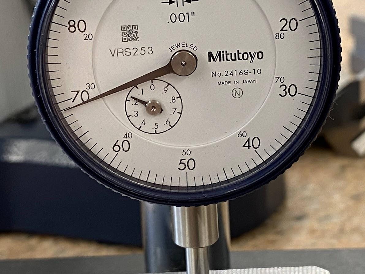
All dial drop indicators are similar in that they have a dial with two needles. The smaller needle will record how many complete revolutions the large needle has made, and the large needle indicates how many smaller graduations have been made. In the inch indicator above, the large needle shows arm travel in .001″ increments. While the amount of travel will vary according to the indicator model, the one inch is most common. While measuring, the drop arm slides up and down within the indicator, which is why it’s called a dial drop indicator.
In the example above, the dial indicator is being used to measure the depth of a counterbore. The indicator was “zeroed” on the top of the part at .700″.
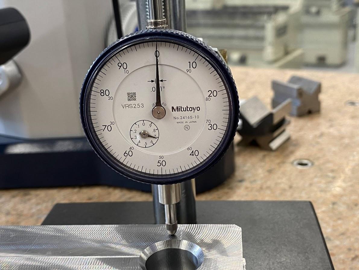 Figure 4.20. The dial indicator stem touching the top of a part and the small needle indicating .7” and the larger needle indicating zero./ Image Credit: Damon Donner, CC BY 4.0
Due to the nature of the indicator, the indicator is at zero travel when the arm is fully extended. The operator has decided to load the dial indicator with .700″ of travel in the drop arm.
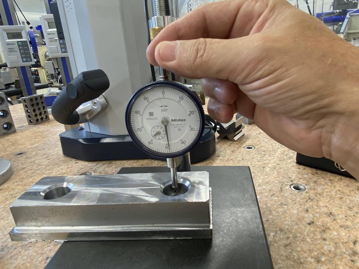
With the top surface datum recorded at .700″, the indicator is dropped into the counterbore to rest against the counterbore shoulder.
Once the drop arm rests on the bottom of the counterbore, you can take a reading of the indicator dial. Since the small indicator is below the two, it is reading in the .100″ range. Add the large needle reading of .069″ and we have a current reading of .169″. Subtract that number from the starting zero of .700″ and we have a counterbore depth of .531″. This method is a quick way to measure a feature when performing several specific dimension measurements, such as during a production run.
Dial indicators have a ⅜” stem, which can be used to secure the indicator in many different styles of holders. The figure above is a NOGA brand indicator stand.
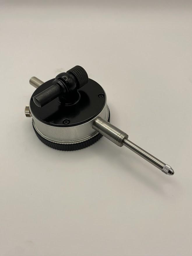
Figure 4.124. The backside of a dial indicator with a 5/16” pin attached. / Image Credit: Damon Donner, CC BY 4.0
The backs of most dial indicators have a lug for attaching mounting hardware, such as this 5/16″ post.
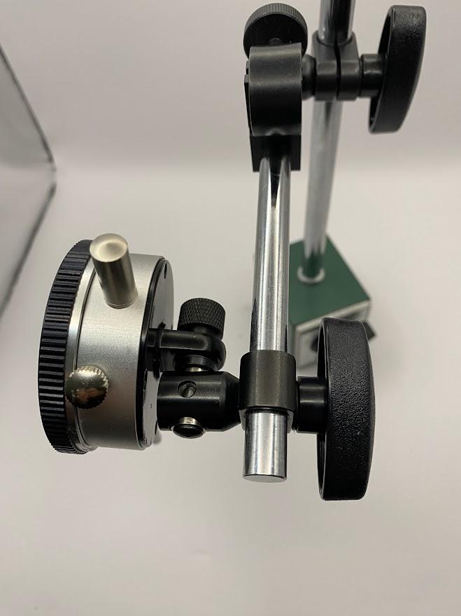
The figure above illustrates how the back lug on a test indicator can mount on a magnetic base. In this instance, a spacer shim had to be added to fit the stand (see silver inside clamp).
Attributions
- Figure 4.119: Dial drop indicator measuring a counterbore depth by Damon Donner, for WA Open ProfTech, © SBCTC, CC BY 4.0
- Figure 4.120: Dial indicator zeroed at .700″ by Damon Donner, for WA Open ProfTech, © SBCTC, CC BY 4.0
- Figure 4.121: Dial indicator being dropped into a counterbore by Damon Donner, for WA Open ProfTech, © SBCTC, CC BY 4.0
- Figure 4.122: Dial indicator face by Damon Donner, for WA Open ProfTech, © SBCTC, CC BY 4.0
- Figure 4.123: Dial indicator held by â…œ” stem by Damon Donner, for WA Open ProfTech, © SBCTC, CC BY 4.0
- Figure 4.124: Back of a dial indicator by Damon Donner, for WA Open ProfTech, © SBCTC, CC BY 4.0
- Figure 4.125: Back lug attached to a magnetic base by Damon Donner, for WA Open ProfTech, © SBCTC, CC BY 4.0
