4.14 Test Indicator
D.M. Donner
Test indicators vary in several characteristics from drop dial indicators, the first being the resolution of the indicator. The most popular test indicators have a resolution of .0005″ however there are .001″ graduations as well as .0001″ if necessary. This means that every line is a half thou, .0005″. Resolution like this makes reading fine variations easier than a .001 graduation dial.
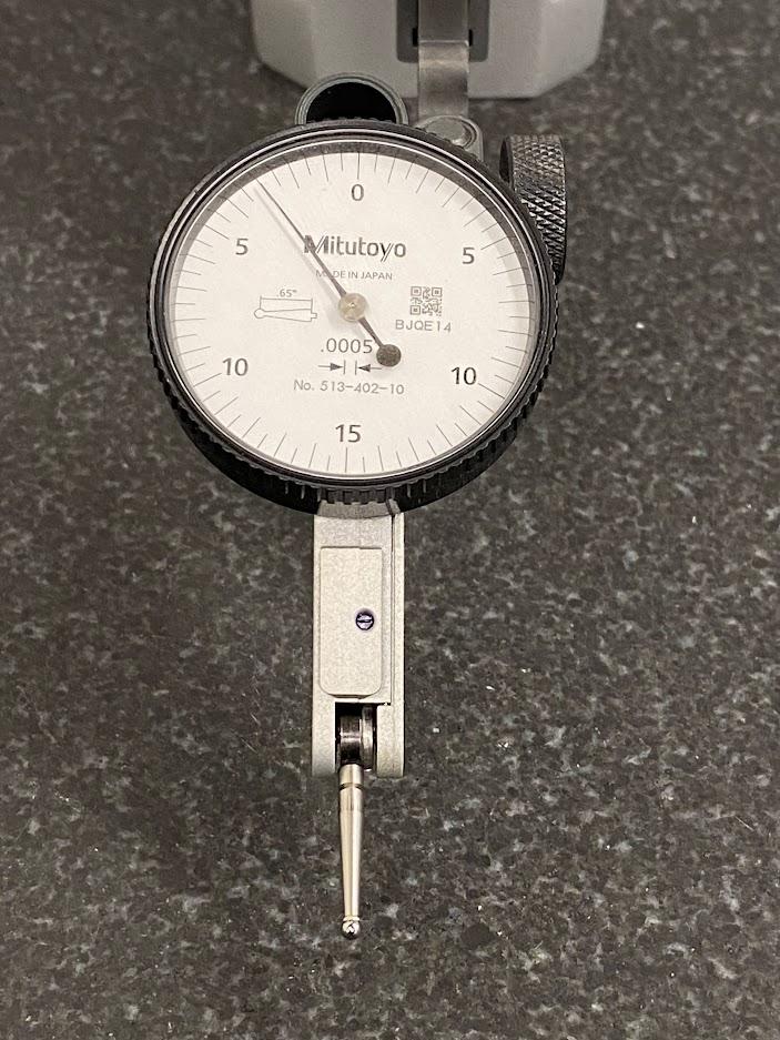
Figure 4.127. The face of a test indicator and a symbol of two arrows pointing at two parallel lines indicating each line segment is .0005”./ Image Credit: Damon Donner, CC BY 4.0
The dial above has .0005″ resolution, and a dial that only makes one revolution, or .030″ travel. Due to this limited travel, test indicators are only used for very fine measurements.
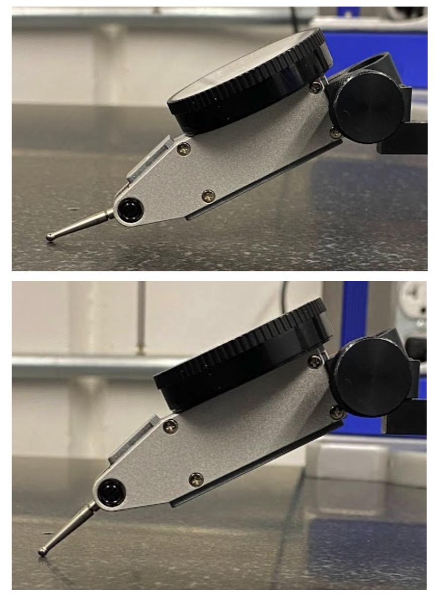
The above figures illustrate how the indicator contact points can be moved to intercept the datum surface at the correct angle. The top example is the angle desired to eliminate the cosine error induced by having too steep an angle on the contact tip. A cosine error is induced by the contact point not being set to the correct sweep angle in relation to the contact arm swivel point.
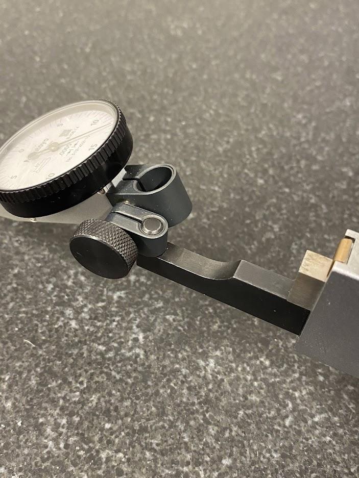
There is no industry standard for mounting test indicators however, the dovetail feature allows for test equipment to be mounted with very little interference from the connected equipment. Above, a test indicator has been mounted onto a height gage using a dovetail accessory.
Attributions
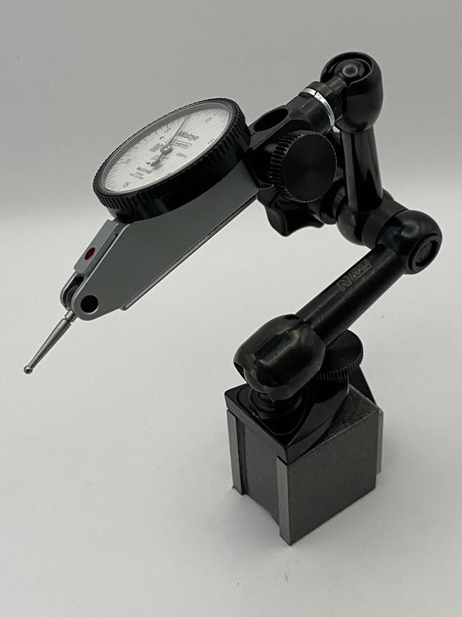
- Figure 4.126: Test indicator on a magnetic base by Damon Donner, for WA Open ProfTech, © SBCTC, CC BY 4.0
- Figure 4.127: Test indicator with .0005″ resolution by Damon Donner, for WA Open ProfTech, © SBCTC, CC BY 4.0
- Figure 4.128: The contact points on test indicators are movable by Damon Donner, for WA Open ProfTech, © SBCTC, CC BY 4.0
- Figure 4.129: Dovetail connection by Damon Donner, for WA Open ProfTech, © SBCTC, CC BY 4.0
