4.4 Height Gages
D.M. Donner
Height gages of various styles are used throughout the machining industry. These tools are quite versatile. Usually found on top of granite surface plates, height gages come in varying heights to suit the needs of a task. They are referred to as gages, but they are also capable of performing direct-read measuring.
Height gages are a measuring tool found in all machine shops. The versatility of a height gage makes it the primary tool on most surface plates. There are digital, vernier, and dial height gages; however, with the low cost of digital measuring equipment, digital is more common.
When placed on a surface plate, the height gage references the surface plate, and points on the part such as counterbores, thru holes, blind holes, and stepped features for a datum. The gage’s versatility comes from the many accessory attachments that can be mounted on it. The attachment point is very basic, permitting a simple clamping arrangement.
Height Gage Attachments
The above figure shows the common clamping system on most height gages. This simple design is one of the key reasons that the height gage is so popular. A thumb screw clamps the attachment inside the clamping sleeve. Simply loosen the thumb screw to change the attachments.
Scribe
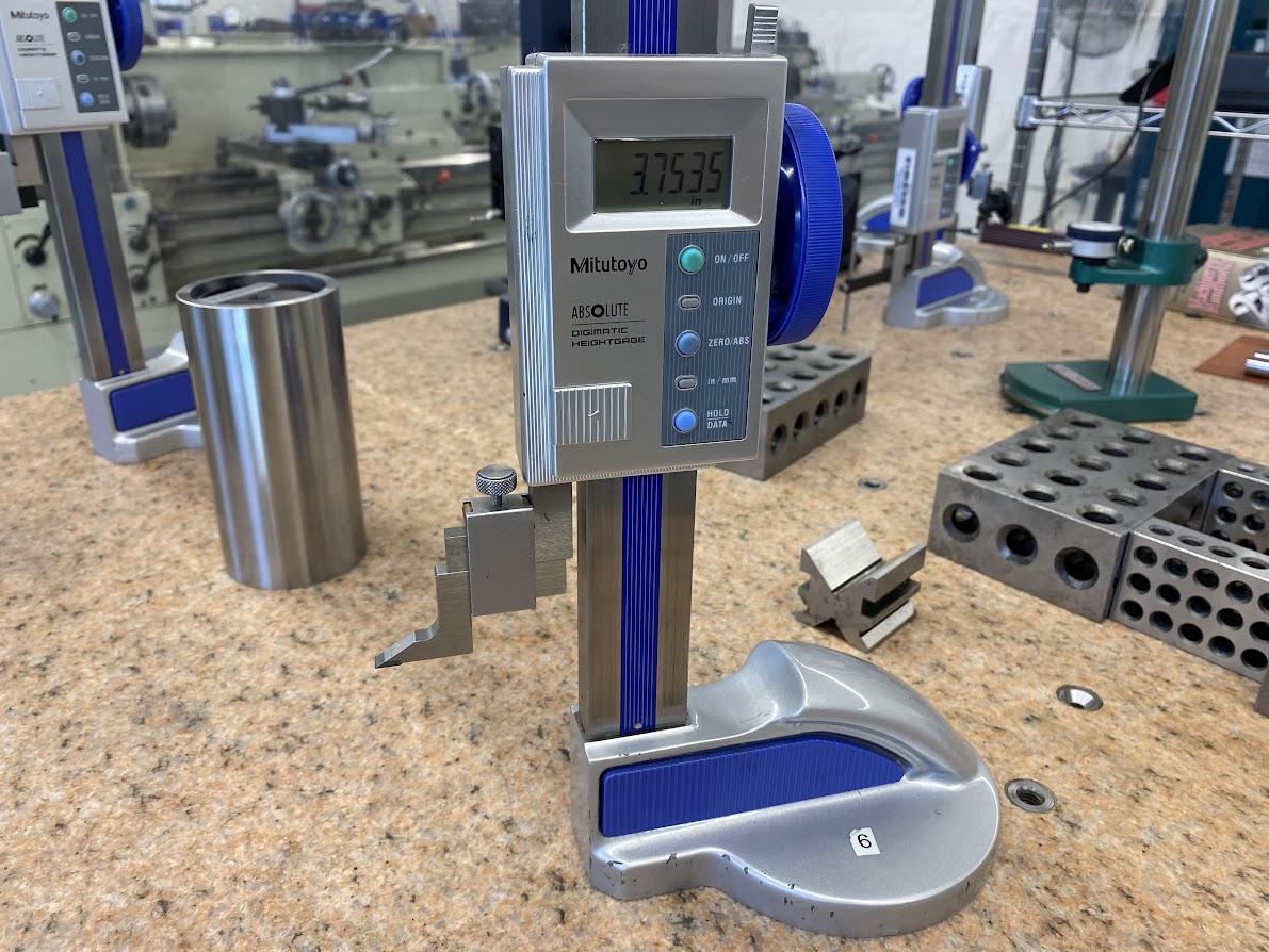
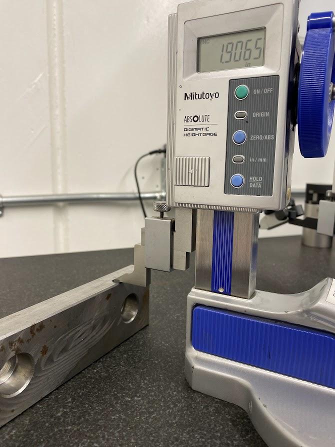
The scribe attachment can be used to scribe a surface for layout purposes, or to create a flat bottom surface for performing length measurements. Use a gentle touch when measuring height with a scribe attachment. An operator can lift the height gage by applying too much force which will prevent accurate measurement.
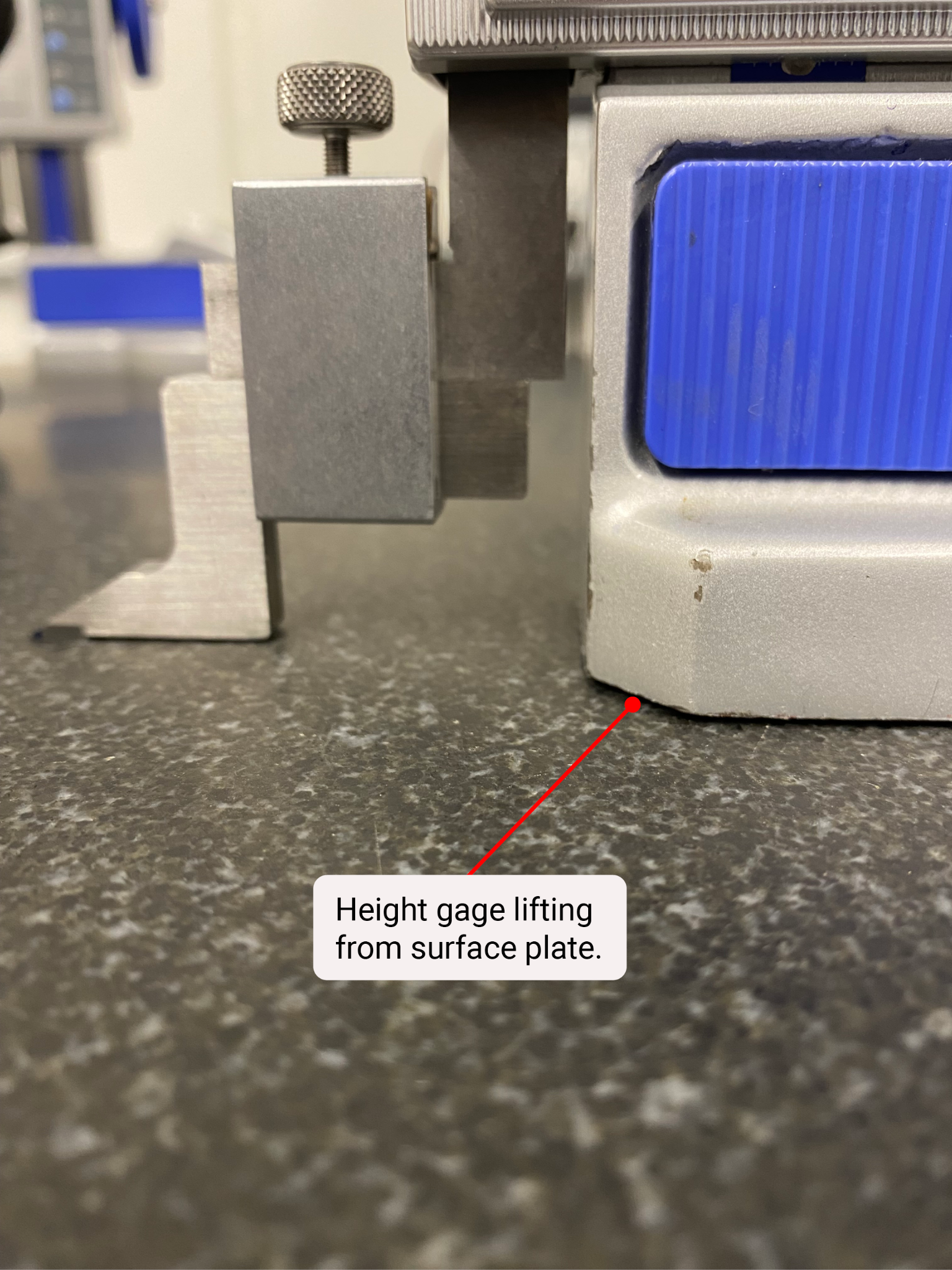
The figure above illustrates lifting from applying too much force to the height control knob. Touching the surface plate when registering the datum to zero and touching the surface that is to be measured can also cause the gage to lift. When the gage lifts, measurements are inaccurate.
To perform a height measurement, perform the following steps:
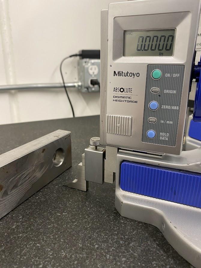
- Zero the scribe against the surface plate datum by gently touching the plate with the scribe and then pressing the “ZERO/ABS” button.
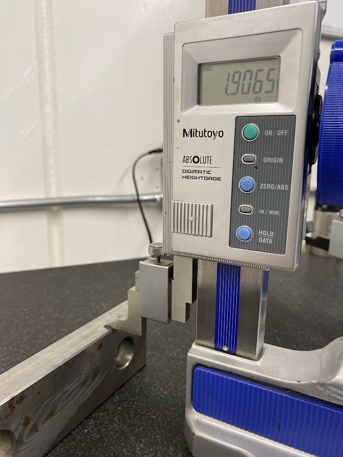
- Raise the scribe and gently touch the top datum surface with the scribe.
- Read the height measurement from the digital readout for the dimension.
Depth Gage Attachment
The figure above has a depth gage attachment which is being used to measure the depth of a counterbore. The depth probe is gently touched off against the datum surface of the object and the indicator is zeroed.
The depth gage is moved to the bottom of a counterbore, and the depth is read on the height gage display.
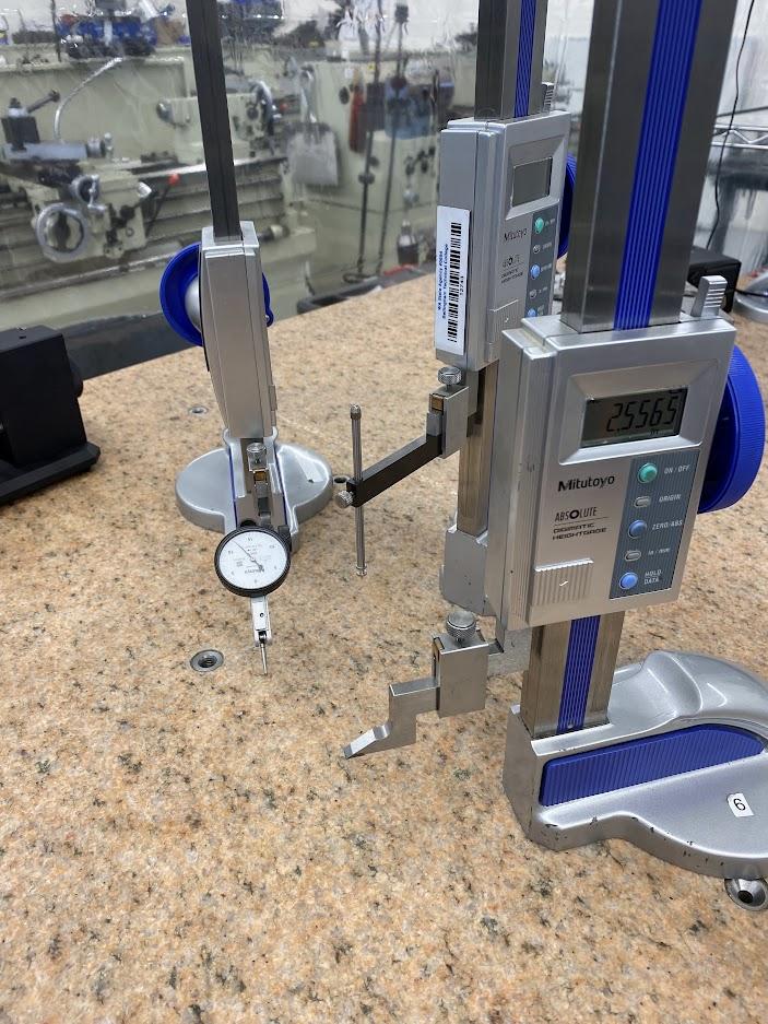
Test Indicator
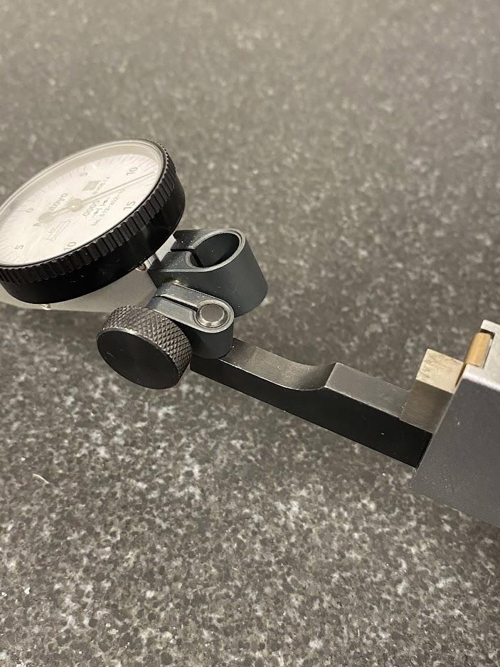
A test indicator can be affixed to the height gage using an indicator bar and clamp. The figure above demonstrates the dovetail style clamp attaching to the test indicator case. There are additional bar styles for popular test indicator models.
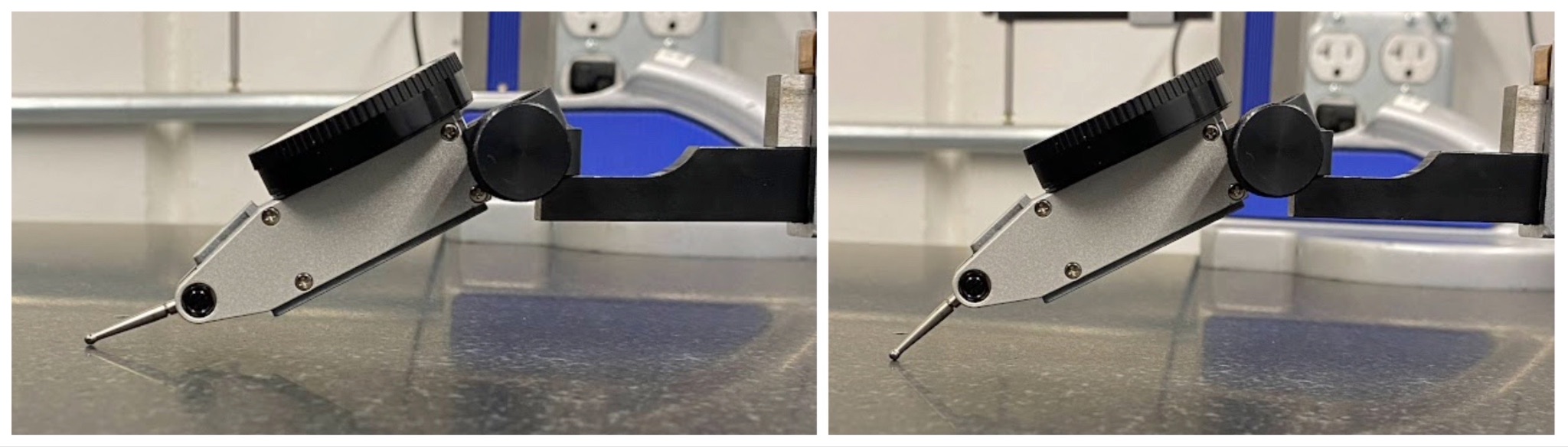
Using a test indicator on a height gage allows the operator to perform extremely accurate measurements due to the test indicator’s fine resolution. However, the approach angle of the test indicator needs to be less than 20° to prevent cosine error. An angle greater than 20° can add ten thousandths to a measurement. The test indicator contact points may be adjusted up and down by applying pressure to the pointer against the friction fit of the threaded swivel.
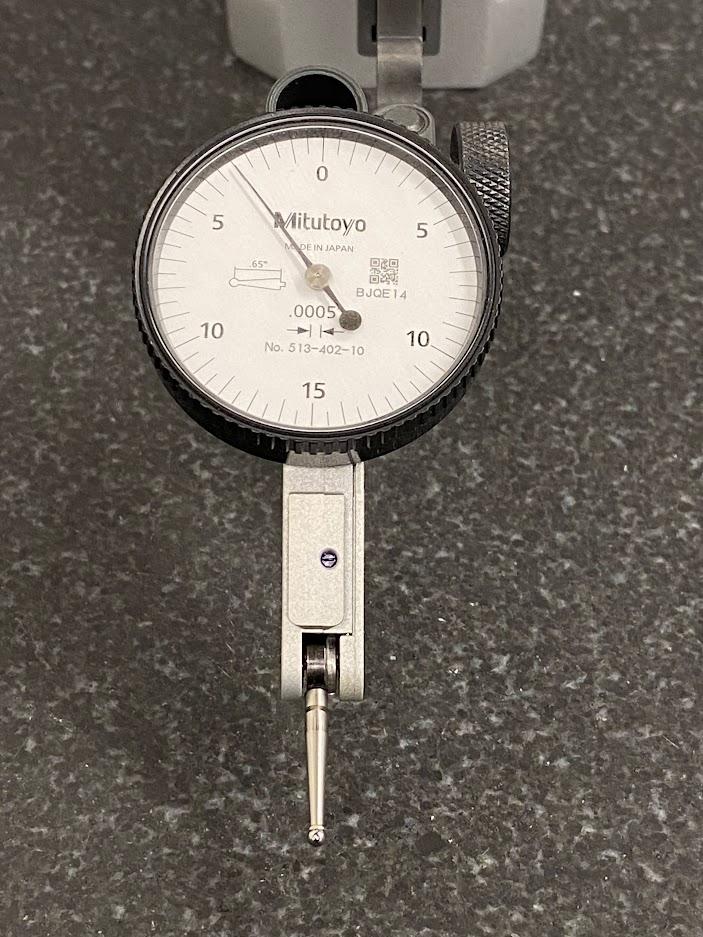
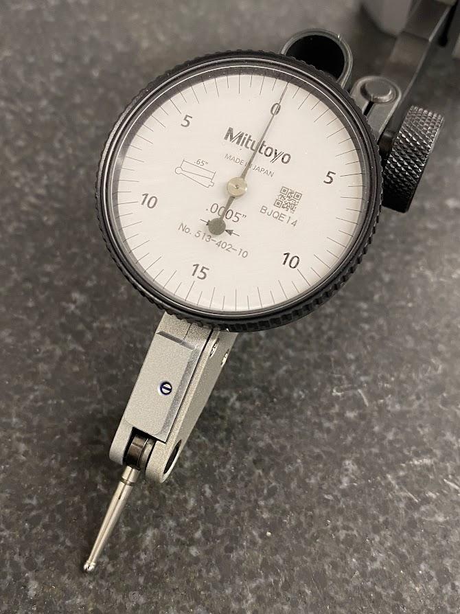
A test indicator has a bezel (which the numbers are attached to) that can be rotated to suit the operator. The figure above has the zero at the top, away from the contact point.
The indicator above is in the no load position meaning the pointer is not contacting any surface. Notice the needle rests at -.007″ from zero. The purpose of this feature is to allow the operator to “preload” the indicator which permits a plus and minus swing of the dial during use. To preload the indicator simply touch the indicator’s contact point against the surface to be measured and turn the height gage dial until the test indicator reads zero. Now, when you sweep the point across the surface to be measured, you can find the high spot by watching the indicator needle.
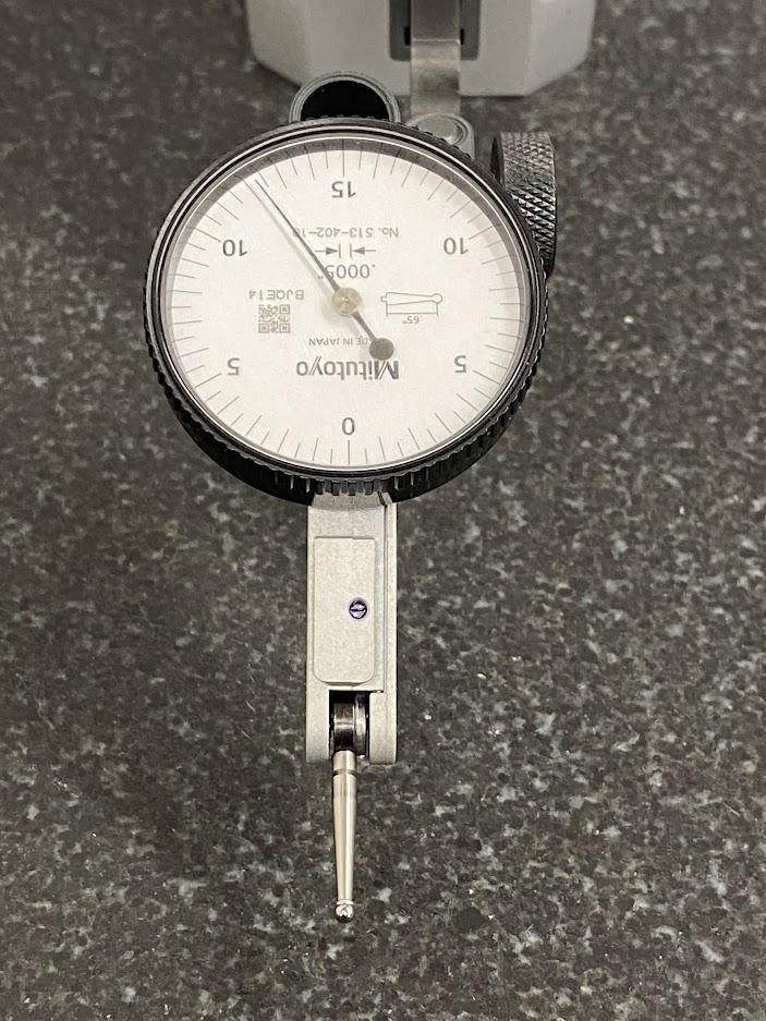
In the figure above, the indicator dial is rotated with the zero at the bottom. The advantage of one over the other is the needle’s ability to swing in both the negative and positive directions. With the dial’s zero on the bottom, you are permitted more range for sweeping surfaces and testing for a high spot. With the dial’s zero on the top, the needle has very little travel in the negative direction and can prevent an accurate reading.
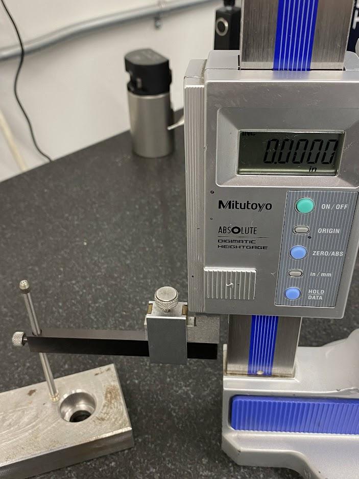
Once the test indicator is zeroed against the datum surface, zero the height gage without moving the height adjustment. You now have the datum set, and you are ready to measure.

Once the test indicator has been zeroed using the adjusting knob on the height gage, you may zero the height gage indicator by pressing “ZERO/ABS”. This step pairs the height gage with the test indicator. This coupling helps the operator attain accurate measurement when sweeping a dimension datum to find the highest point from which to measure.
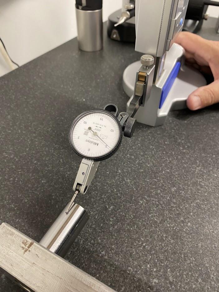
After setting a zero datum on the surface plate, the test indicator is moved to the top of an inspection pin placed in the counterbore of the vice jaw being measured.
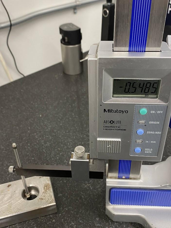
The indicator is swept back and forth by moving the height gage while watching the test indicator. When the test indicator measures the highest reading, stop the sweep.

Raise or lower the height gage until the test indicator reads the same zero that was set against the surface plate datum.
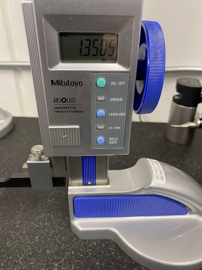
Figure 4.93. Read the Height Gage to Get the Measurement/ Image Credit: Damon Donner, CC BY 4.0
When all of the steps have been performed accurately, the height indicator will display the height to the top of the pin. Since the inspection pins are precision ground for accuracy, subtracting the radius of the pin will provide the distance from the surface plate to the center of the counterbore.
Cleaning a Height Gage
It is important to clean a height gage to remove resistance caused by a dirty piece of equipment. The height gage suffers many of the same influences as the slide calipers. Contamination from operators’ hands and general shop air collects on the surfaces causing friction when moving the sliding height adjuster. Many of the techniques used to clean calipers are the same here.
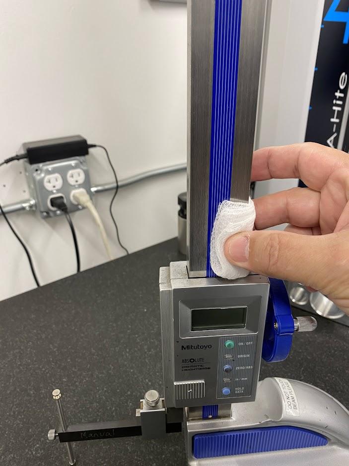
Moisten a lint free cloth with alcohol and wipe the beam surfaces. Contamination collects here from the oil on the operator’s hands. Unfortunately, the beam is such a prominent feature of the height gage that operators often use it as a handle when transporting the device.
However, a height gage should never be transported by grabbing the beam. Doing so can cause contamination and damage to the beam. Always grasp the height gage by the base to transport it. A stabilizing hand can be rested against the beam to prevent tipping while transporting.
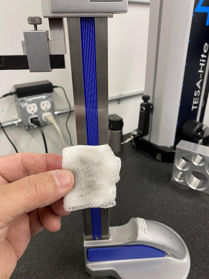
The image above shows how much contamination can accumulate on a height gage beam. This example is not very bad because this height gage resides in a metrology lab where parts have usually been cleaned before measuring, and the operator’s hands are not as dirty. This digital indicator has an encoder strip under the blue strip on the beam. Since the measuring component in the slide assembly reads the surface of the encoder strip, excess moisture must be removed from this surface before use to prevent indicator malfunctions.
Attributions
- Figure 4.77: Height gage on a surface plate by Damon Donner, for WA Open ProfTech, © SBCTC, CC BY 4.0
- Figure 4.78: Height gage accessory clamp by Damon Donner, for WA Open ProfTech, © SBCTC, CC BY 4.0
- Figure 4.79: Height gage with scribe attachment by Damon Donner, for WA Open ProfTech, © SBCTC, CC BY 4.0
- Figure 4.80: Height gage lifting by Damon Donner, for WA Open ProfTech, © SBCTC, CC BY 4.0
- Figure 4.81: Using a scribe attachment to measure height by Damon Donner, for WA Open ProfTech, © SBCTC, CC BY 4.0
- Figure 4.82: Using a scribe to touch the top surface of a vise jaw by Damon Donner, for WA Open ProfTech, © SBCTC, CC BY 4.0
- Figure 4.83: Height gage drop attachment by Damon Donner, for WA Open ProfTech, © SBCTC, CC BY 4.0
- Figure 4.84: Height gage depth attachment measuring a counterbore depth by Damon Donner, for WA Open ProfTech, © SBCTC, CC BY 4.0
- Figure 4.85: Test indicator attachment by Damon Donner, for WA Open ProfTech, © SBCTC, CC BY 4.0
- Figure 4.86: Adjustable test indicator needle angle by Damon Donner, for WA Open ProfTech, © SBCTC, CC BY 4.0
- Figure 4.87: Zero the dial indicator by Damon Donner, for WA Open ProfTech, © SBCTC, CC BY 4.0
- Figure 4.88: Indicator dial rotated with zero at the bottom by Damon Donner, for WA Open ProfTech, © SBCTC, CC BY 4.0
- Figure 4.89: Zero the height gage by Damon Donner, for WA Open ProfTech, © SBCTC, CC BY 4.0
- Figure 4.90: Zero height gage by Damon Donner, for WA Open ProfTech, © SBCTC, CC BY 4.0
- Figure 4.91: Sweeping a pin by Damon Donner, for WA Open ProfTech, © SBCTC, CC BY 4.0
- Figure 4.92: Resetting the dial indicator by Damon Donner, for WA Open ProfTech, © SBCTC, CC BY 4.0
- Figure 4.93: Read the height gage to get the measurement by Damon Donner, for WA Open ProfTech, © SBCTC, CC BY 4.0
- Figure 4.94: Cleaning a height gage by Damon Donner, for WA Open ProfTech, © SBCTC, CC BY 4.0
- Figure 4.95: Contamination removed from the beam by Damon Donner, for WA Open ProfTech, © SBCTC, CC BY 4.0
