4.7 Bore Gages
D.M. Donner
Bore gages are used to measure bore diameter in comparison to the inspection standard. In order to use a bore gage, the operator must install the required anvils and/or shims to create a length approximating the bore diameter dimension.

Bore gages come with replaceable anvils. The operator must choose the anvil to fit the desired bore.

The above figure shows the correct anvil installed on a bore gage to measure a 1″ bore.

After installing the anvil on the bore gage that relates to the bore being measured, the bore gage is placed into a special inspection standard called a ring gage. A ring gage is a cylindrical device used to measure the outside diameter of features. Ring gages are precision ground to tight tolerance.
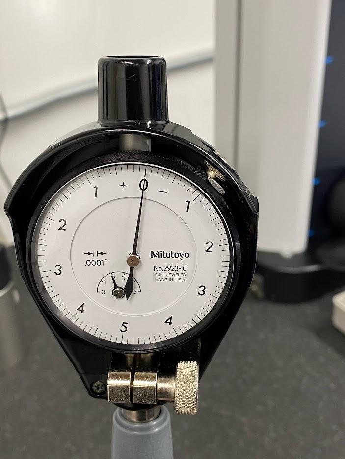
With the anvils inside the standard, the dial is rotated until the needle rests on the zero. The bore gage is now set to the stand diameter.

With the bore gage set up correctly, it is transferred to the bore to be measured.
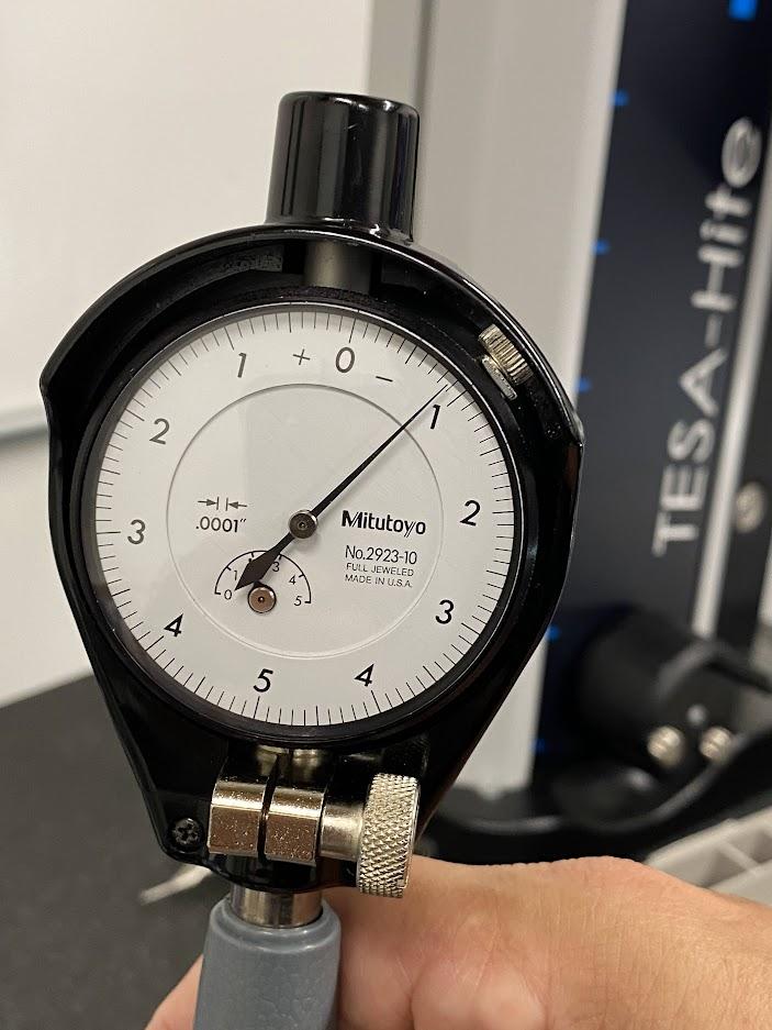
The dial shows the bore size compared to the standard used to set up the gage. In this example, the indicator is showing a negative .0009″. Add this dimension to the standard diameter and you have the measured bore size.
Attributions
- Figure 4.101: Bore gage anvils by Damon Donner, for WA Open ProfTech, © SBCTC, CC BY 4.0
- Figure 4.102: Anvil installed on bore gage by Damon Donner, for WA Open ProfTech, © SBCTC, CC BY 4.0
- Figure 4.103: Bore gage inside a ring gage standard by Damon Donner, for WA Open ProfTech, © SBCTC, CC BY 4.0
- Figure 4.104: Bore gage dial set to zero by Damon Donner, for WA Open ProfTech, © SBCTC, CC BY 4.0
- Figure 4.105: Bore gage inside a bore by Damon Donner, for WA Open ProfTech, © SBCTC, CC BY 4.0
- Figure 4.106: Dial indicating bore diameter by Damon Donner, for WA Open ProfTech, © SBCTC, CC BY 4.0
