4.8 Pin Gages
D.M. Donner
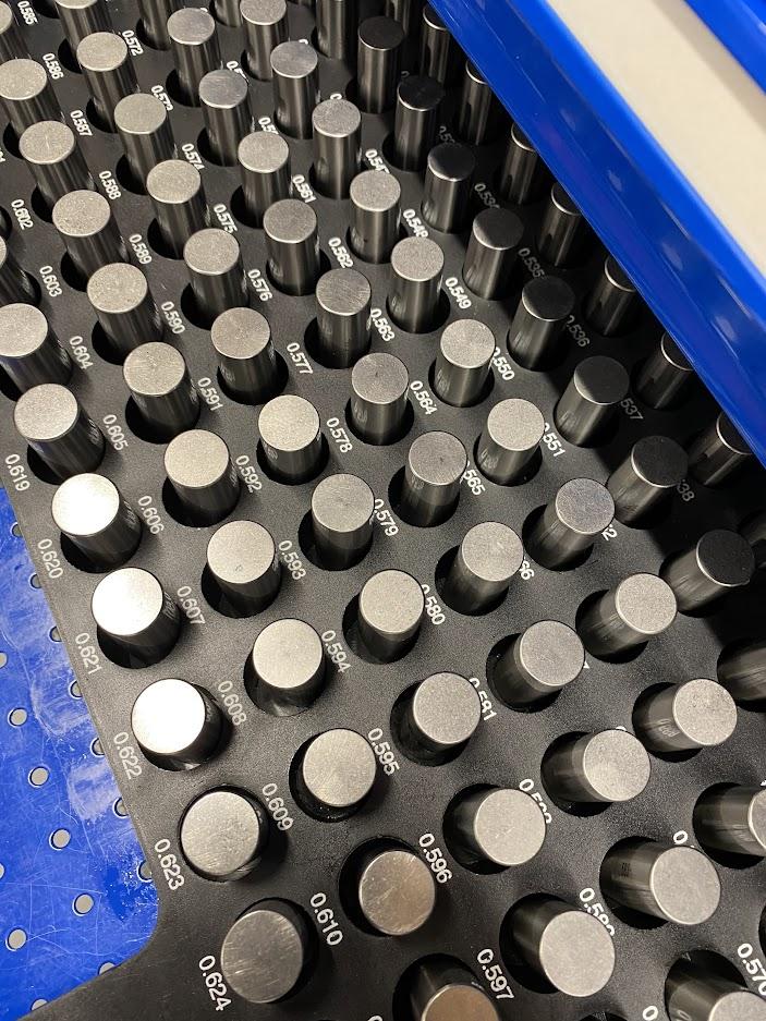
Pin gages are precision ground cylindrical gages used to measure holes and bores. Pin gages come in sets. The figure above is a set of minus gages from .501 to .625 in .001″ increments.
Minus gages are ground .0002″ undersized. The purpose of this is to allow the pin to fit into a cylindrical feature of the nominal size printed on the pin. Nominal refers to the intended size dimension without any tolerance applied. If a .500″ pin was ground to .500″ it would not fit into a .500″ feature.

Gage pins come in minus and plus sizes. The tolerance to which they have been ground defines how much they are undersized or oversized.
The two most common tolerance sizes of gage pins are Z and ZZ. Z tolerance is +.0000 -.0001″ for minus pins, and +.0001 – .0000 for plus pins. ZZ tolerance is +.0000 -.0002″ for minus pins, and +.0002 -.0000 for plus pins.
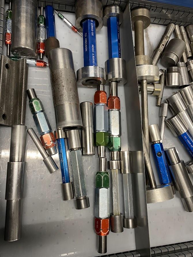
Pin gages are great for go/no-go gaging of a hole feature. The figure above shows a drawer of go/no-go pin gages for operators to use in production. The pin holders have a green and red cap that has a precision collet beneath it to hold a pin. If you are measuring a dimension of a .375″ hole with a tolerance of +.000 -.005″, you would place a .375″ plus pin in the red end, and a .370″ minus pin in the green end. During production, the go/no-go pin is quickly used to gage a hole to ensure it is within tolerance.
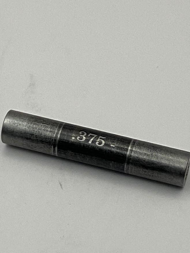
Gage pins are plain or coated with a black oxide finish that will show wear, alerting the operator that the pin needs to be replaced. Replacement pins can be ordered individually to replace worn or missing pins. The above .375″ pin has been used extensively and needs to be replaced.
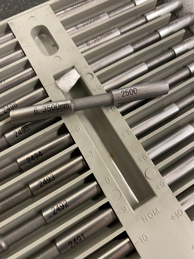
A tighter tolerance pin is an X or XX tolerance which is .00004″ and .00001″ respectively. They are kept in a metrology lab until they are needed for measurement. The figure above is an X tolerance pin set for .2500″ ∓ .001″ in .0001″ increments. This set consists of a nominal pin, in this case .2500″, and ten minus pins in .0001″ increments, as well as ten plus pins in .0001″ graduations. They are only used for very tight tolerance holes, such as in an aerospace press fit situation.
WARNING! Do not force pins into a hole. Pins must slide into a hole with minimal effort. Forcing pins into holes where they do not fit will result in the pin becoming lodged so tightly that the part and pin may become scrap.
Attributions
- Figure 4.107: Pin gage set by Damon Donner, for WA Open ProfTech, © SBCTC, CC BY 4.0
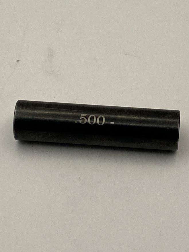
- Figure 4.108: .500″ minus pin gage by Damon Donner, for WA Open ProfTech, © SBCTC, CC BY 4.0
- Figure 4.109: A .500″ minus pin being measured with a micrometer by Damon Donner, for WA Open ProfTech, © SBCTC, CC BY 4.0
- Figure 4.110: Drawer of go/no-go pin gages by Damon Donner, for WA Open ProfTech, © SBCTC, CC BY 4.0
- Figure 4.111: Gage pin with black oxide coating by Damon Donner, for WA Open ProfTech, © SBCTC, CC BY 4.0
- Figure 4.112: X ∓ tolerance pin set for .2500″ by Damon Donner, for WA Open ProfTech, © SBCTC, CC BY 4.0
Please look for related terms in the Glossary
