5.10 Workholding
D.M. Donner
Workholding is the process of securing and holding a workpiece firmly in place during various machining operations. The primary goal of workholding is to ensure that the workpiece remains stable and properly positioned while it undergoes cutting, shaping, drilling, milling, or other machining processes.
Benchwork is usually performed with the work securely clamped in a bench vise. Most workbenches have a vise mounted on them.
Bench Vise
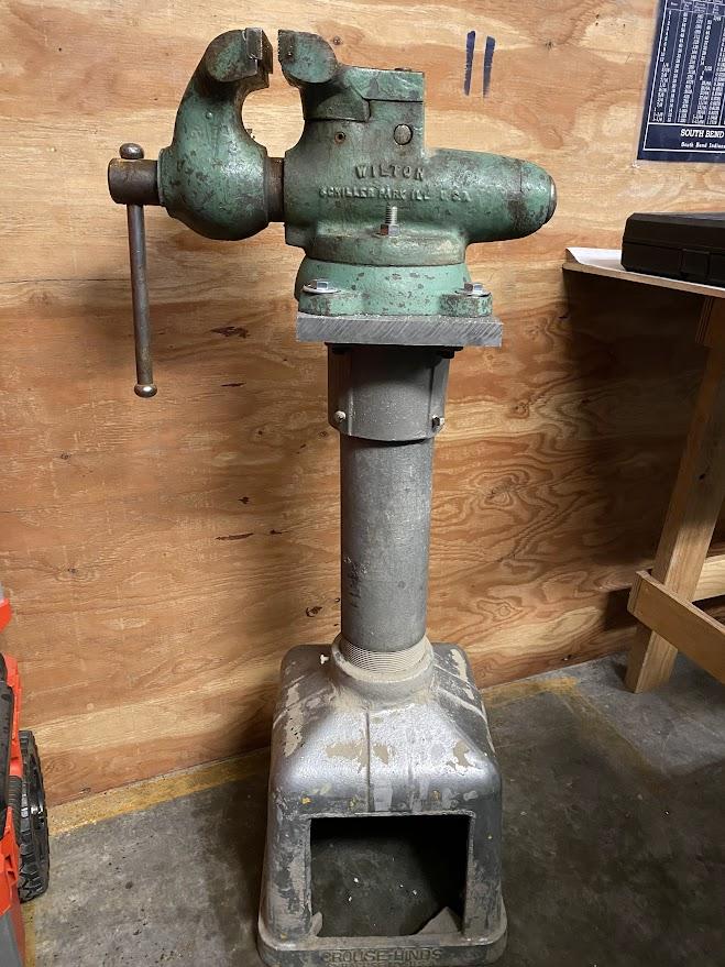
The bench vise in the figure above is mounted on a pedestal, which makes it a pedestal vise. These vises are mounted to workbenches because the mass of the work bench helps stabilize the vise while we twist, turn, pull, and hammer on the stock clamped in its jaws. The pedestal vise not only wobbles but also requires that a foot be placed on the base to prevent motion.
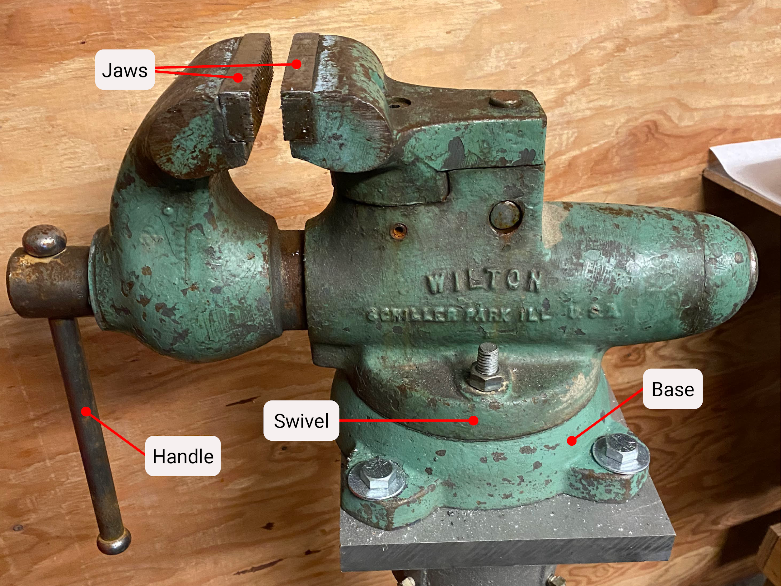
The features of a vise make it a useful workholding device. The base of the bench vise is secured with four ⅝” hex bolts, providing extremely high shear strength. The top of the vise has a swivel joint to allow convenient positioning of the clamping jaws around this pivot. The jaws are replaceable, allowing for different jaws to be installed depending on the desired use. Vise sizes refer to how far the vise jaws open as measured between the jaw faces. Lastly, the vise handle is robust, allowing for extreme lever forces to be applied.
The amount of clamping applied by a bench vise is a product of the handle (lever) length times the force applied to the handle divided by the pitch of the vise screw. Let’s use some numbers to calculate the clamping force of this bench vise. Assume the following:
Weight applied to the handle= 150 lbs.
Vise handle length = 9″
Pitch of this vise’s lead screw = .200″
We calculate clamping force by multiplying weight applied to handle and handle length, divided by lead screw pitch.
150 × 9 / .200 = 6750 lbs. of force
That is a considerable amount of force considering we have not added a cheater bar yet or added another person to the force applied to the handle. A cheater bar is a longer lever applied to a wrench/handle to increase the lever force applied.
Clamps
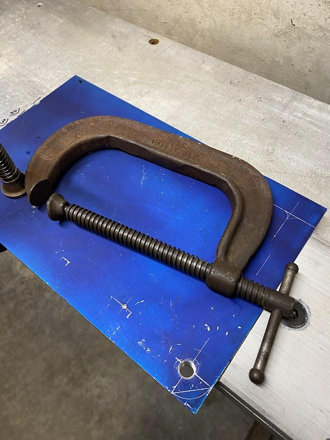
Another workholding devise is the C-clamp. C-clamps get their name from the shape of their body. A very simple clamping tool, they come in many sizes and materials. It is harder to find quality C-clamps these days because they require high quality hammer forged steel to perform to the maximum design intent.
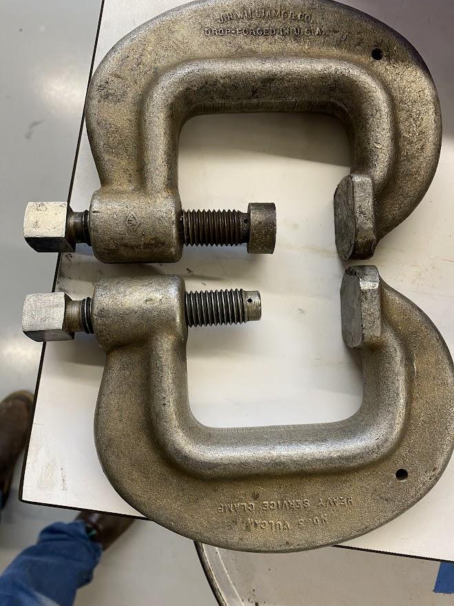
The figure above is an example of a sturdy C-clamp. The body is made from thick forged steel which will prevent flexing under clamping forces. The acme style thread is made of quality steel able to withstand the axial forces of the screw. At the end of the threaded shaft is a swivel foot which provides a strong interface between the twisting clamp and the stationary stock material. The threaded shaft terminates with a ball. This ball acts as a bearing pressing against the foot. The foot has a slip fit with the ball and there is a roll crimp on top of the ball to prevent separation. With a quality handle, the clamping forces available are considerable.
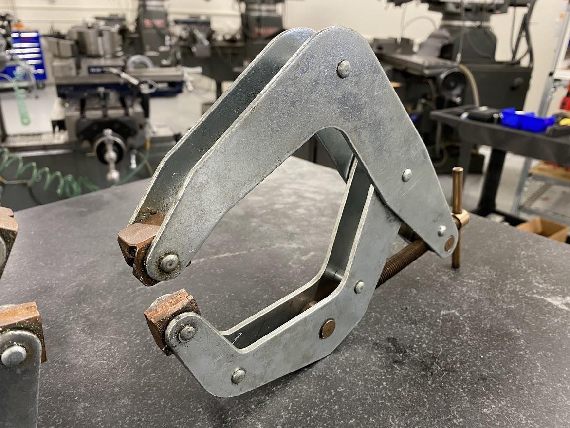
With the lack of affordable forged steel C-clamps, innovation has created a popular style of clamp called a Kant Twist© Clamp. It is made from simple sheet steel, rivets and brass. They come in many sizes and perform well.
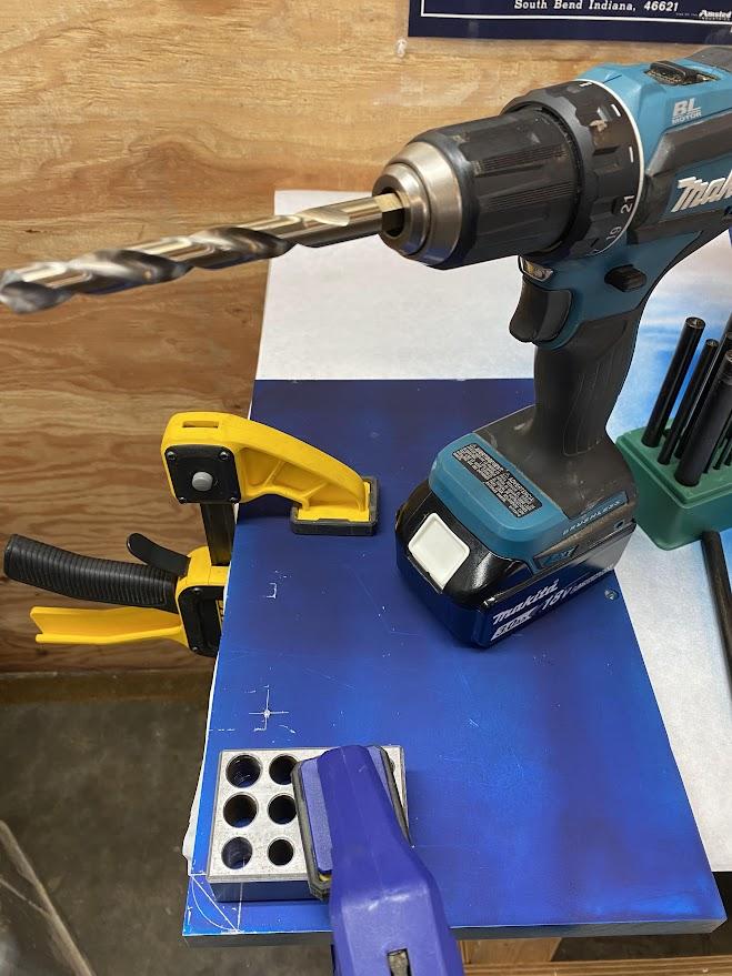
Another economical clamp solution are bar trigger clamps which apply a considerable force and come in many sizes allowing for clamping larger materials.
Attributions
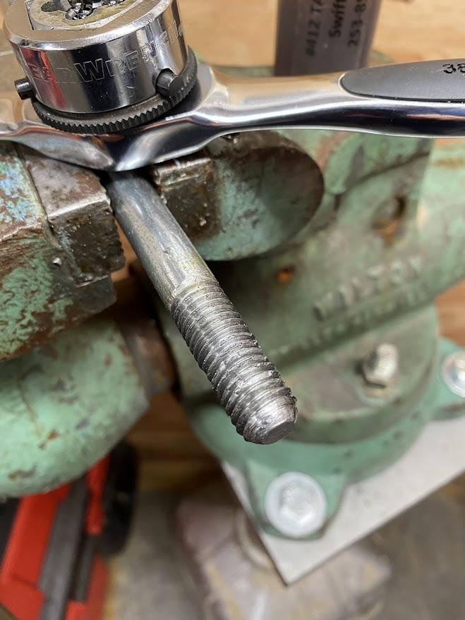
- Figure 5.88: Holding round stock while threading by Damon Donner, for WA Open ProfTech, © SBCTC, CC BY 4.0
- Figure 5.89: Bench vise mounted on a pedestal by Damon Donner, for WA Open ProfTech, © SBCTC, CC BY 4.0
- Figure 5.90: Parts of a bench vise by Damon Donner, for WA Open ProfTech, © SBCTC, CC BY 4.0
- Figure 5.91: C-clamp by Damon Donner, for WA Open ProfTech, © SBCTC, CC BY 4.0
- Figure 5.92: C-clamp missing the contact pad by Damon Donner, for WA Open ProfTech, © SBCTC, CC BY 4.0
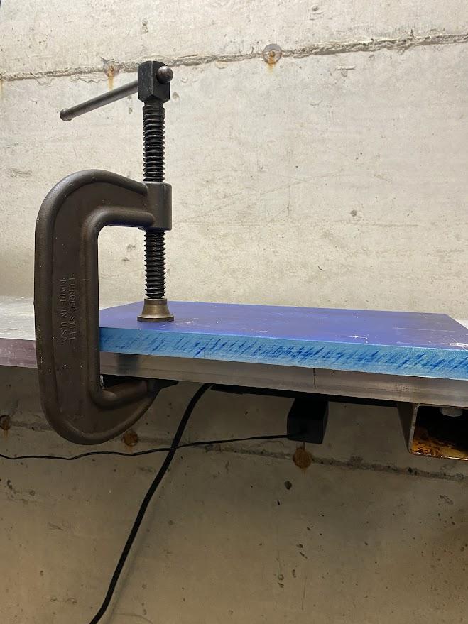
- Figure 5.93: C-clamp holding stock to a workbench by Damon Donner, for WA Open ProfTech, © SBCTC, CC BY 4.0
- Figure 5.94: Kant Twist clamp by Damon Donner, for WA Open ProfTech, © SBCTC, CC BY 4.0
- Figure 5.95: Bar/spreader clamps by Damon Donner, for WA Open ProfTech, © SBCTC, CC BY 4.0
the process of securing and holding a workpiece firmly in place during various machining operations
Please look for related terms in the Glossary
