5.4 Layout: Straight Lines
D.M. Donner
There are two types of lines in layout, straight lines and arcs. Remember, we are performing semi-precise layout where we employ different tools and techniques to achieve the goal of accuracy. A better understanding of these factors will aid you in creating a quality layout.
Steel Rules
The most basic tool used to create a straight line is a rule. Machinists prefer steel rules which come in differing lengths and widths, and they can be rigid or flexible. The six-inch rule sits nicely in a shirt pocket and can be used for quick, semi-precise measurements. A steel rule is made from quality steel that won’t rust and has numerical increments engraved along its edges. Graduations are in inches, metric, fractional, or decimal.
The steel rule has four edges on which graduations are etched. Graduations can be in 8ths, 16ths, 32ths and 64ths of an inch, as well as 10ths, 50ths and 100ths. The metric ruler has 1/2 mm and 1 mm graduations. Some rulers come with markings on the short end of the ruler to fit into tight spaces.
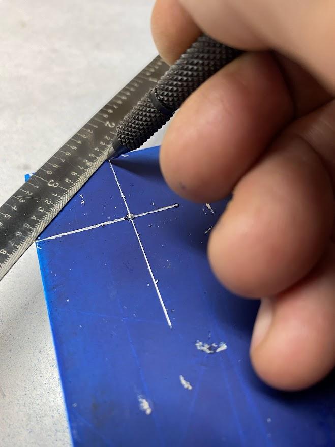
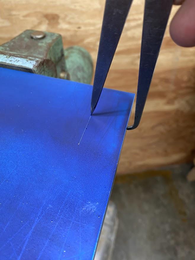
To layout a straight line with a steel rule, the operator must visually line up the edge of the rule with a layout mark. This step is the most critical. A misplaced ruler will produce a misplaced scribe line, so take time to align the ruler accurately.
Once the ruler is in place, use a sharp scribe to drag along the edge of the ruler, being careful not to move the ruler during the scribing process. Tilt the scribe to ensure the point is against the edge of the ruler.
Firm Joint Caliper
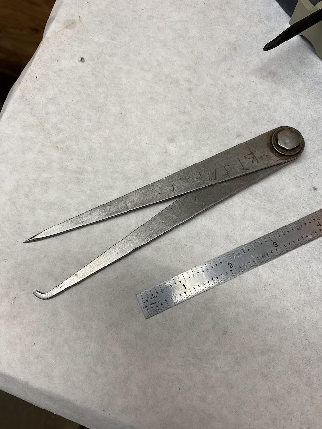
Another low-tech method for creating a straight line parallel to an edge is to use a special type of firm joint caliper referred to as an odd leg caliper, where one leg is straight and used for scribing and the other leg is bent and designed to follow the edge of the stock. A firm joint caliper is a comparison device that has two legs that are held together by friction.
Parallel refers to the relationship between two items in which the two items sit side-by-side with equal distance between them at all points. For example, a layout line and the edge of the stock can be arranged in parallel.
To create a straight layout line using an odd leg caliper, the edge of the stock must be flat and free of burrs. Draw file the edge if necessary to achieve this condition. Draw filing is a finish filing process intended to remove a small, controlled amount of material and achieve a smooth finished surface.
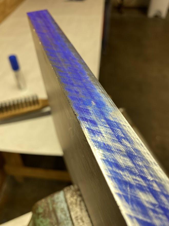
Keeping the file perpendicular (at a right angle) to the stock, drag the file in the direction of the cutting edges on the file, and inspect the edge for high/low spots. Layout dye or permanent marker can be applied to the stock edge to make it easier to see the high and low spots. This is illustrated in the image above.
An odd leg caliper must be set using a ruler to establish the distance from the edge of the stock to the straight layout line. This is the first opportunity for error, so take your time and do it accurately.
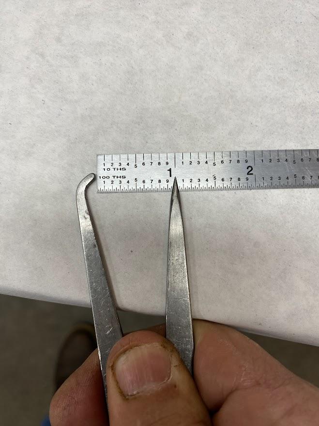
Place the bent leg of the caliper against the end of the ruler and move the scribe leg until it measures the distance desired. If the caliper has a locking system, apply the lock. If friction is used to maintain the caliper position, ensure you do not move the legs during use.
To transfer the distance setting from the ruler to the stock, the operator may use the bent leg to follow the edge of the stock while dragging the scribe point against the material to leave a line. Grip the caliper in a manner that maintains the leg spacing during use.
Squares
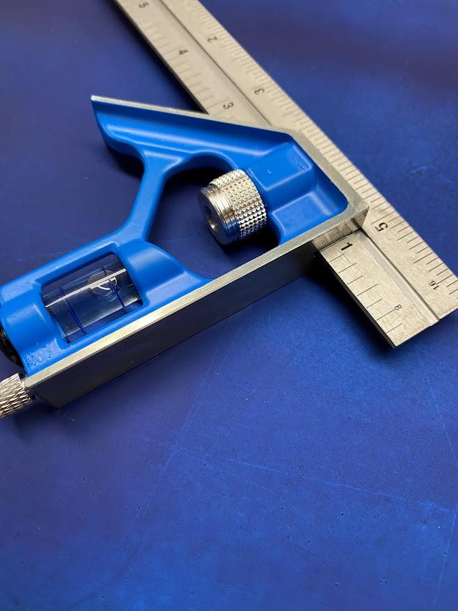
Another layout tool used to create straight lines in relation to the stock’s edge is called a square. The term square also refers to the perpendicular relationship between the datum reference of the edge and the layout line which is at a 90° angle from the edge. For example, you may be asked to square a line from the top edge of the stock. This would be a line perpendicular to the top edge. Precision squares come in fixed and combination types. Combination types can also be used to create lines at a 45° angle to an edge. This is useful when laying out a chamfer.
A square is the preferred tool to create a perpendicular line primarily due to its construction. A square has one edge on the square body referred to as the fence which is used to reference the datum edge. It is flat and usually large enough to allow the operator a firm grasp. The beam is the flat ruler-like blade of metal used to scribe the line. Beams come in varying lengths.
Prepare the datum edge of the stock to ensure flatness and absence of burrs. Lay the blade down flat against the stock and position the square in the desired position to scribe a line. While holding the square in place, drag the scribe along the edge of the blade ensuring the point of the scribe is against the blade.
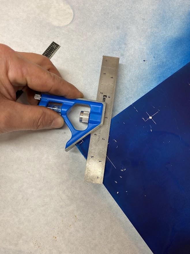
To use the 45° function of a combination square, the operator must reference the other fence on the square body and place that face against the stock.
Slide Caliper
The slide caliper is another tool used to create a straight layout line. The process is similar to that of the odd leg caliper.
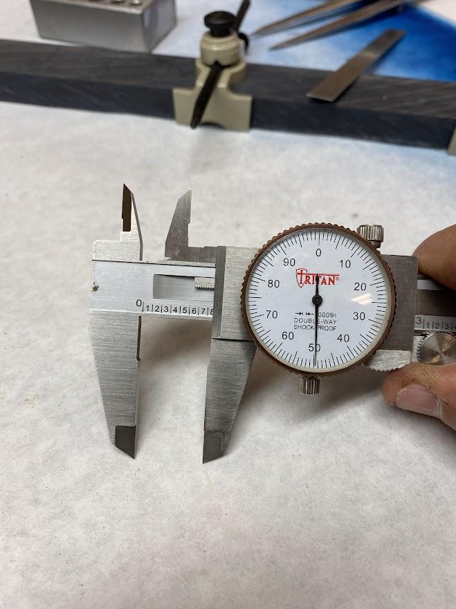
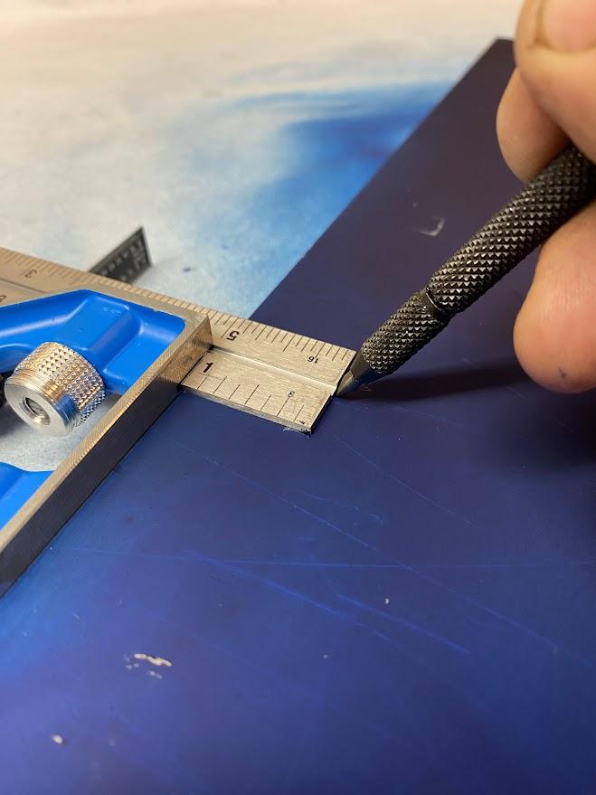
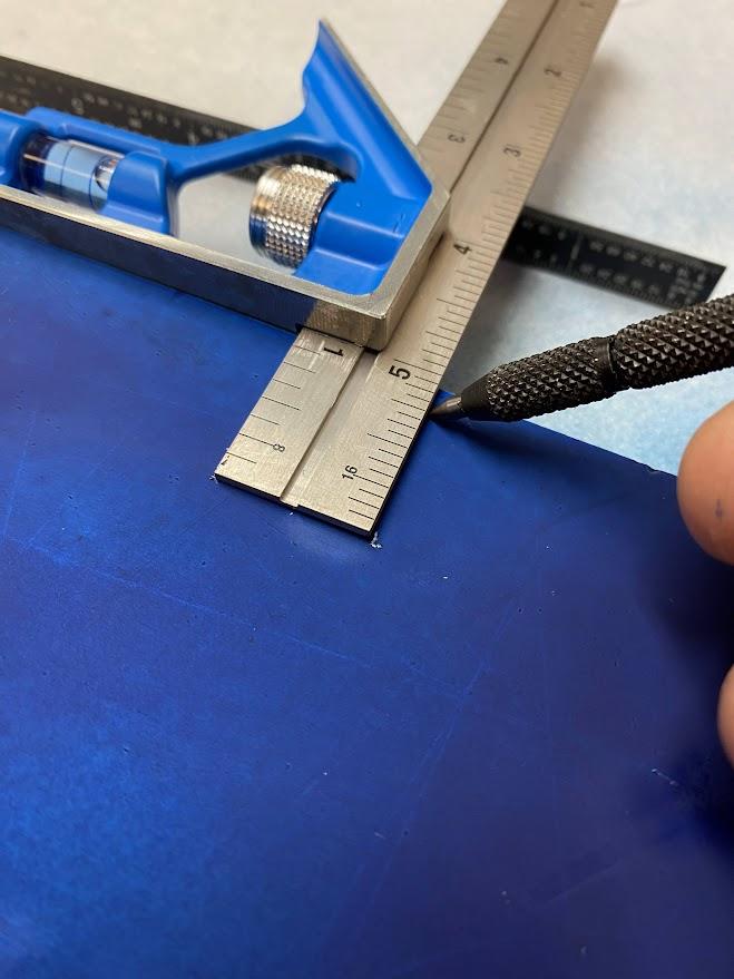
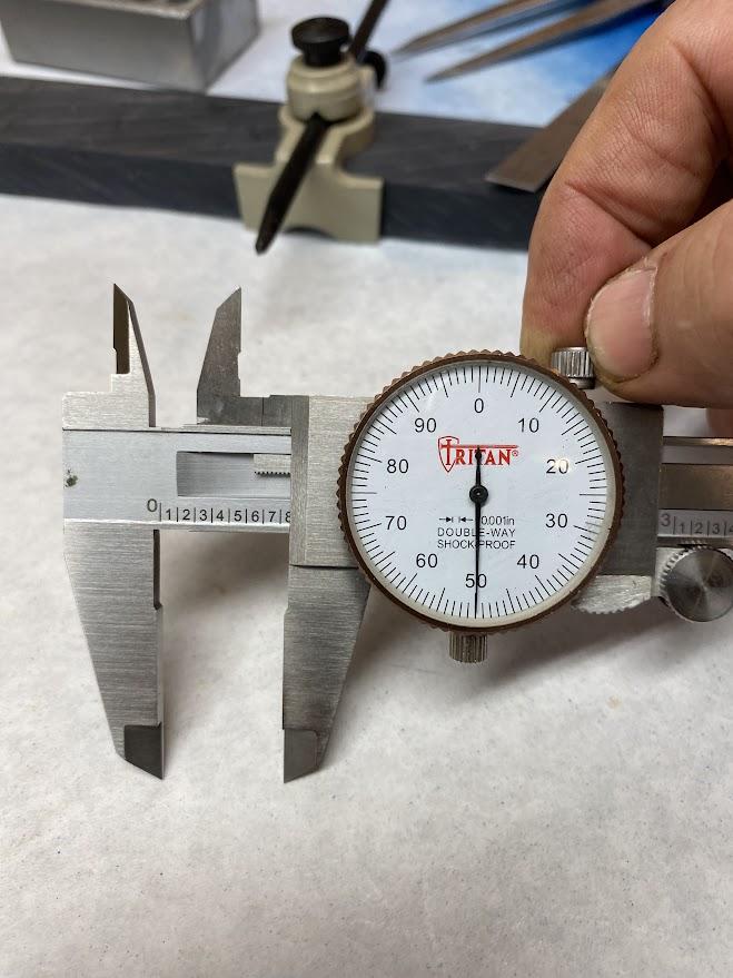
In the figure above, the operator is using the slide wheel to position the caliper at the desired distance (1″). The slide lock (above) must be applied to maintain the distance setting on the caliper.
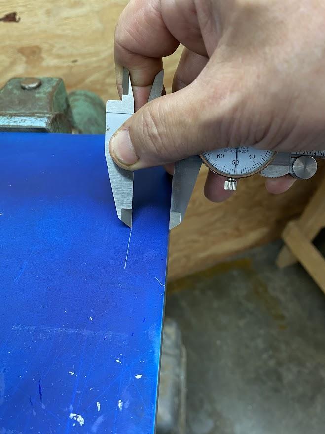
While using the datum edge of the stock to guid the movable leg of the caliper, apply pressure to the stationary leg with just enough force to leave a scribe line while dragging the caliper along the edge.
Attributions
- Figure 5.19: Scribing layout lines with a steel rule by Damon Donner, for WA Open ProfTech, © SBCTC, CC BY 4.0
- Figure 5.20: Odd leg caliper by Damon Donner, for WA Open ProfTech, © SBCTC, CC BY 4.0
- Figure 5.21: Draw file the edge of the stock by Damon Donner, for WA Open ProfTech, © SBCTC, CC BY 4.0
- Figure 5.22: Setting an odd leg caliper using a ruler by Damon Donner, for WA Open ProfTech, © SBCTC, CC BY 4.0
- Figure 5.23: Scribing a line with an odd leg caliper by Damon Donner, for WA Open ProfTech, © SBCTC, CC BY 4.0
- Figure 5.24: Combination square by Damon Donner, for WA Open ProfTech, © SBCTC, CC BY 4.0
- Figure 5.25: A square placed against a datum edge by Damon Donner, for WA Open ProfTech, © SBCTC, CC BY 4.0
- Figure 5.26: Scribing a line using a combination square by Damon Donner, for WA Open ProfTech, © SBCTC, CC BY 4.0
- Figure 5.27: Laying out a 45° line by Damon Donner, for WA Open ProfTech, © SBCTC, CC BY 4.0
- Figure 5.28: Slide caliper set for a 3/4″ by Damon Donner, for WA Open ProfTech, © SBCTC, CC BY 4.0
- Figure 5.29: Apply the slide lock by Damon Donner, for WA Open ProfTech, © SBCTC, CC BY 4.0
- Figure 5.30: Scribing a line with a slide caliper by Damon Donner, for WA Open ProfTech, © SBCTC, CC BY 4.0
device that has two legs that are held together by friction.
refers to the relationship between two items, such as a layout line and the edge of the stock, which extend in the same direction.
A finish file technique where the file is placed perpendicular to the direction of draw and pulled accross the stock.
A layout tool used to create straight lines in relation to the stock's edge
