5.5 Layout: Arcs
D.M. Donner
The other type of layout line is the arc. An arc is any portion of a circle. When working with arcs, we measure radius. There are specialty tools for creating arcs, and there are simple tools we can use to create arcs for layout. Let us begin with purpose-built tools first.
Divider
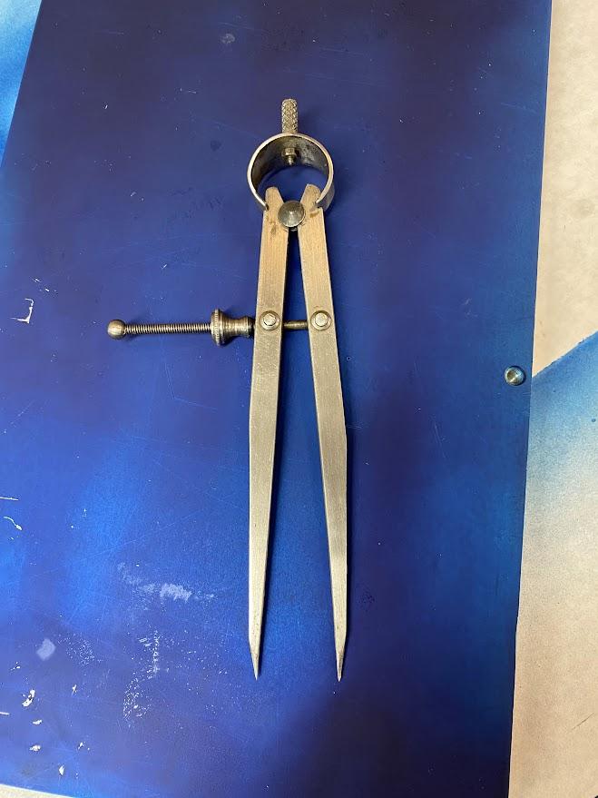
A divider is a tool with two equal length legs with pointed ends.
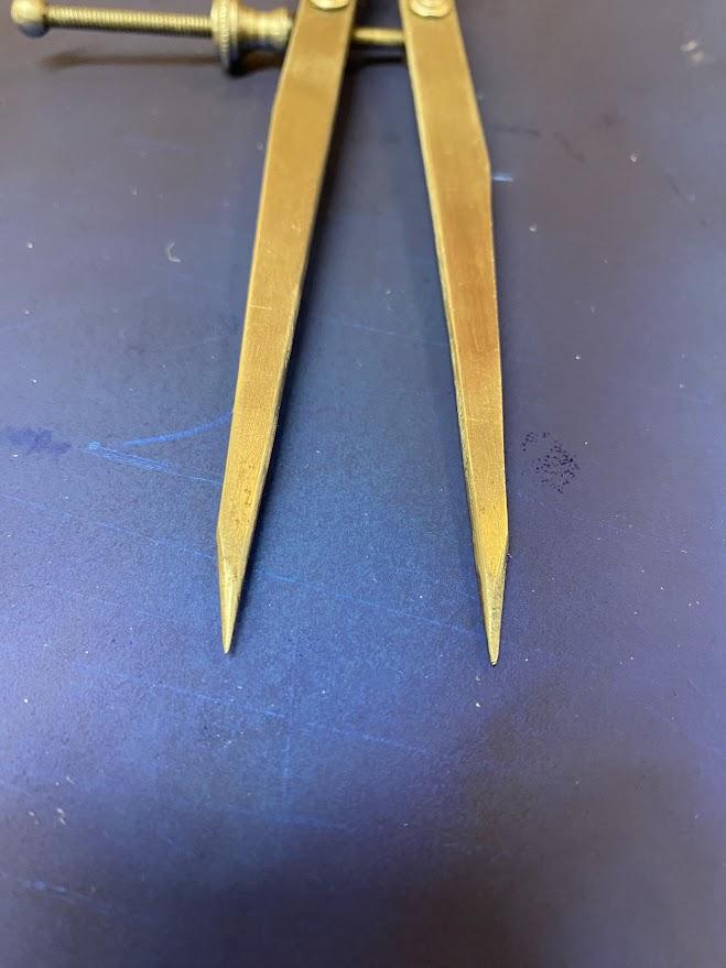
The tips of a divider need to be sharp and pointy. In the figure above, maintenance has been performed over the years to keep the points sharp.
Opposite the sharp tips, the two legs come together at a pivot point. The leg distance is adjusted by tightening or loosening the adjustment nut to bring the legs together or farther apart.
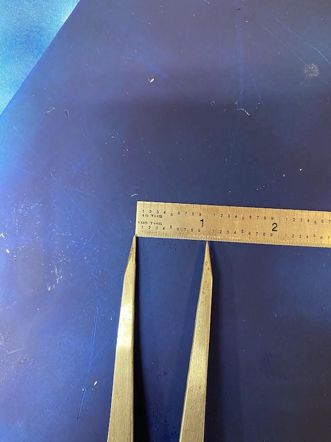
A ruler is used to set the distance between points. This distance will equal the radius of the arc. Once again, sharp points will aid in accurate settings.
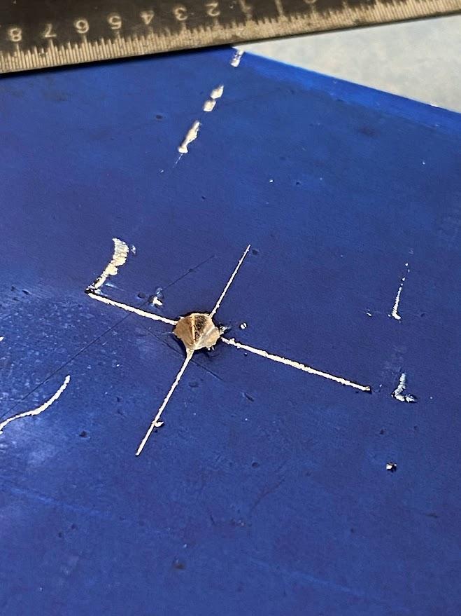
A punch is used to create a conical divot at the center mark of the layout lines. A punch is a tool that is designed to be struck with a hammer. The term conicalmeans cone-shaped, such as an ice cream cone. One point of the divider will reference this punch mark as a center for the arc scribe. This punch mark is rather heavy because it was made with a center punch. A prick punch leaves a smaller divot and is easier to align with the layout lines.
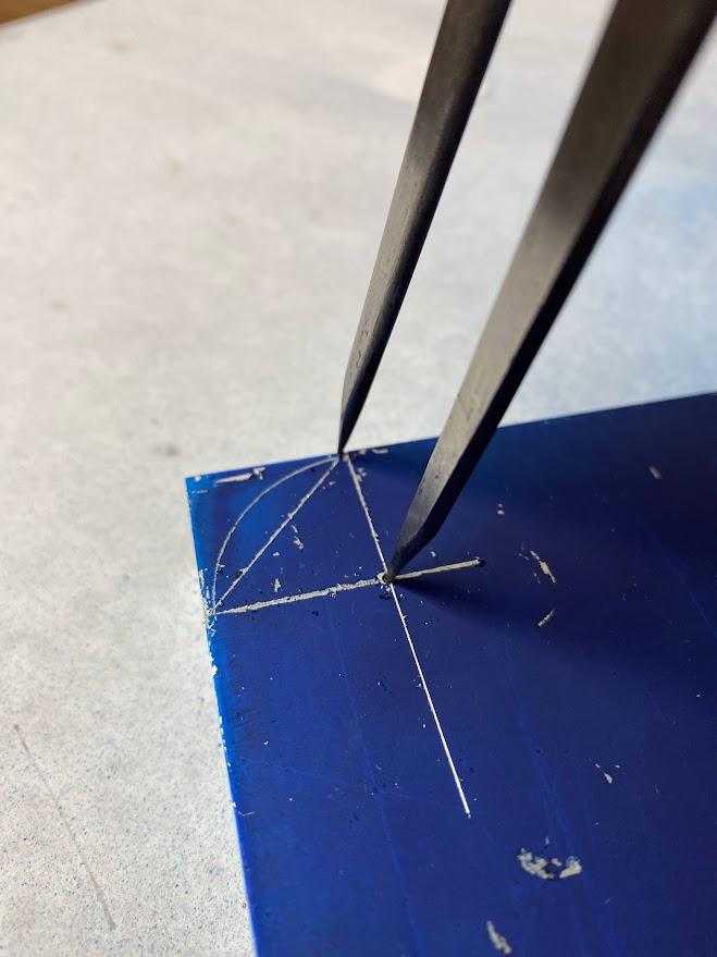
Gently turn the divider around the pivot point of the punch mark to create a clean radius. Dragging the points a couple of times will create more contrast, but be careful not to damage the lines from multiple attempts.
Trammel
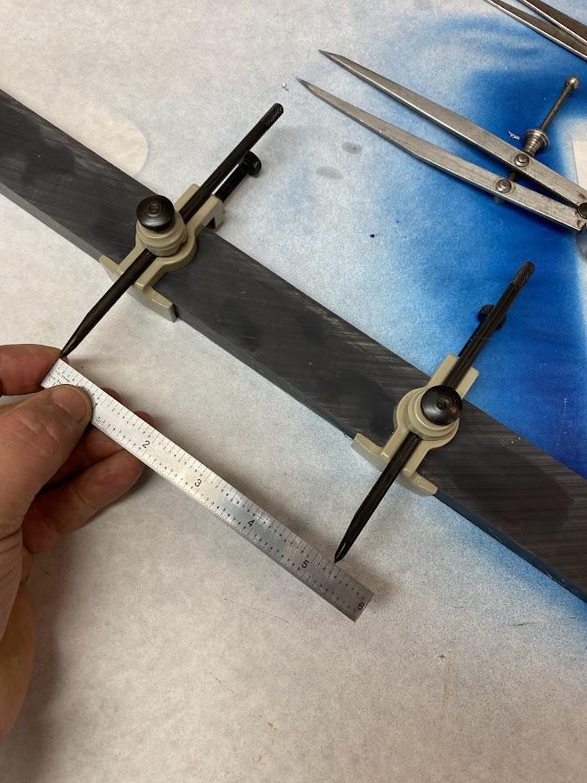
A trammel shares some similarities with the divider in that it uses two points to create an arc; however, a trammel is used for arcs that are too large for smaller tools such as a divider. The trammel’s points are mounted on a beam. In the figure above, the points are set larger than 5 inches and are only limited by the size of the beam.
Gage Pins
What type of circular equipment do we have in abundance in a machine shop? Gage pins. Gage pins are accurately sized and almost infinite in their selection, usually up to one inch.
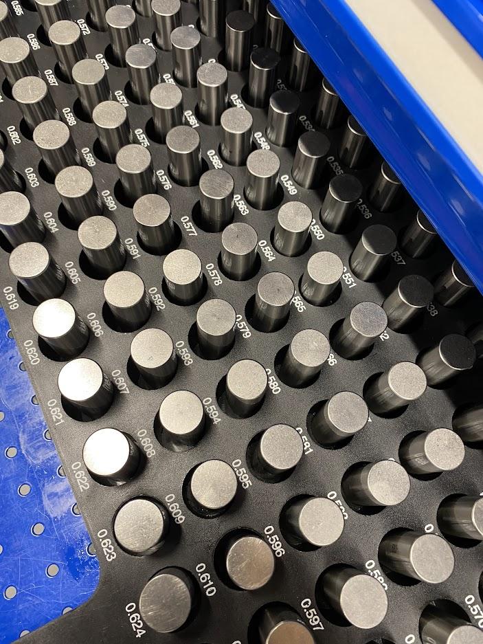
When using a gage pin to lay out an arc, remember to select the pin for the radius of the arc.
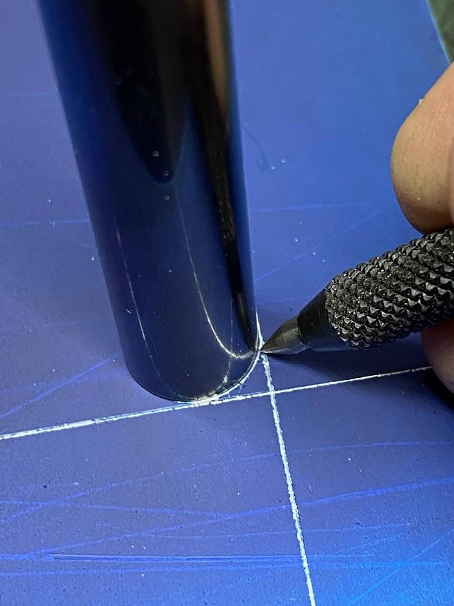
A gage pin is not easy to hold still while tracing the circumference, and the ability of the operator to align the pin with the layout lines also takes some care. Use a gentle touch when scribing the lines to prevent moving the pin.
Radius Gages
Radius gages are another tool at our disposal, but there is a concern we need to address. We are using measuring equipment to perform layout. This is not an accepted practice unless the equipment has been set aside for this purpose. Check with your supervisor before using any inspection equipment to perform layout.
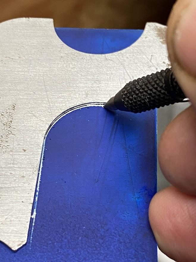
Select the correct radius and place it on the reference marks. In the figure below, two straight lines are laid out with a radius where they meet. The radius gage is much easier to control than a gage pin during the scribe process.
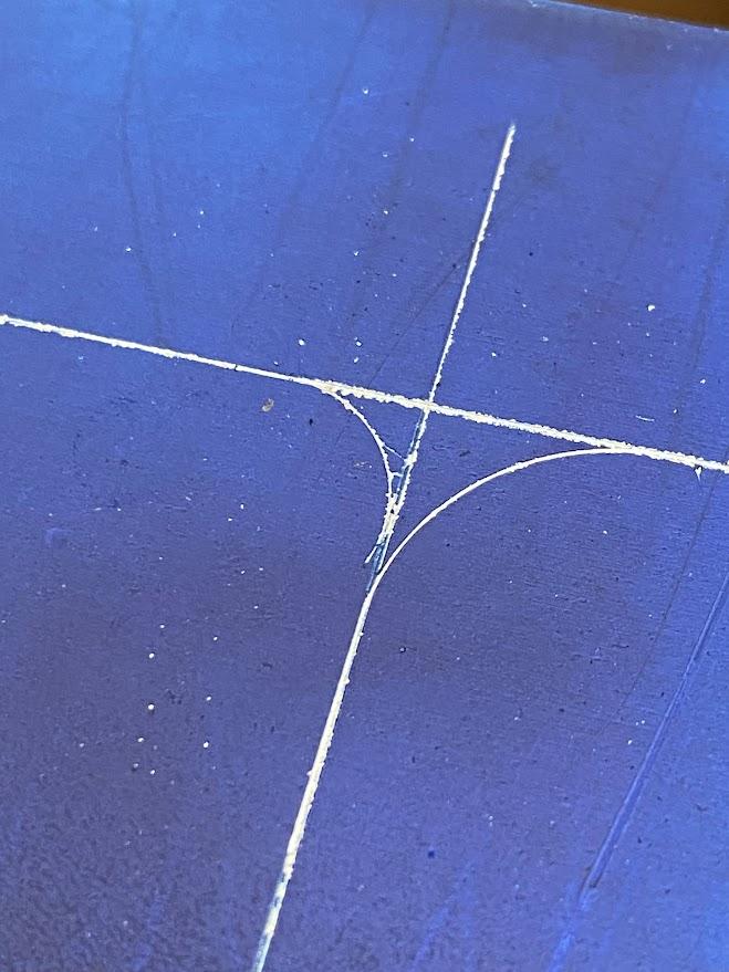
The arc to the left in the figure above was created with a gage pin, and the arc to the right was created using a radius gage. More pressure could be applied with the radius gage, which permitted a deeper scribe.
Attributions
- Figure 5.31: Divider by Damon Donner, for WA Open ProfTech, © SBCTC, CC BY 4.0
- Figure 5.32: Two points on a divider by Damon Donner, for WA Open ProfTech, © SBCTC, CC BY 4.0
- Figure 5.33: Divider legs set to 1″ using a ruler by Damon Donner, for WA Open ProfTech, © SBCTC, CC BY 4.0
- Figure 5.34: A punch mark by Damon Donner, for WA Open ProfTech, © SBCTC, CC BY 4.0
- Figure 5.35: Arc scribe with divider by Damon Donner, for WA Open ProfTech, © SBCTC, CC BY 4.0
- Figure 5.36: Trammel points being set with a ruler by Damon Donner, for WA Open ProfTech, © SBCTC, CC BY 4.0
- Figure 5.37: Gage pins used for laying out arcs by Damon Donner, for WA Open ProfTech, © SBCTC, CC BY 4.0
- Figure 5.38: Using a gage pin to create an arc by Damon Donner, for WA Open ProfTech, © SBCTC, CC BY 4.0
- Figure 5.39: Radius gage to layout an arc by Damon Donner, for WA Open ProfTech, © SBCTC, CC BY 4.0
- Figure 5.40: Arc payout lines by Damon Donner, for WA Open ProfTech, © SBCTC, CC BY 4.0
a tool that is designed to be struck with a hammer
cone shaped, such as an ice cream cone.
