5.7 Punches
D.M. Donner
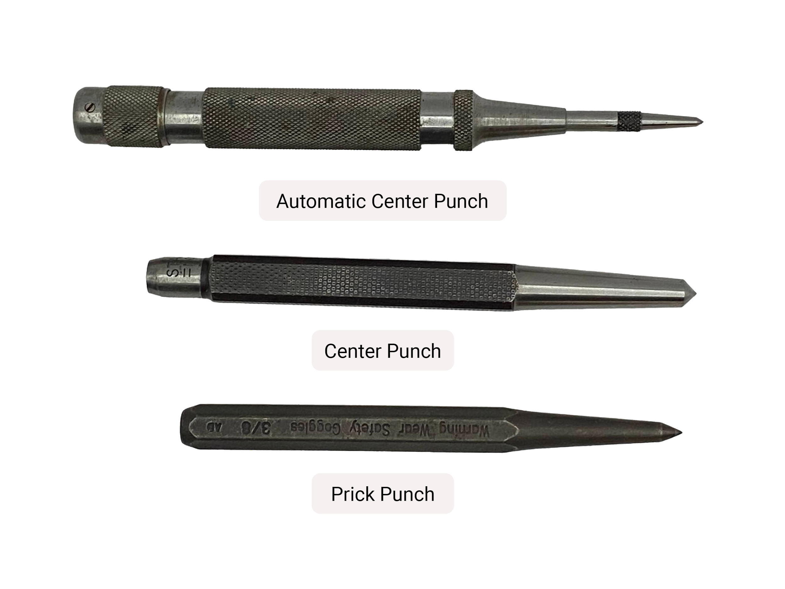
Point style punches are form tools with conical ends designed to be struck with a hammer, leaving a dimple on the stock material. The two general types of punches are center punches and prick punches. Both types of punches are similar, but they have different purposes, and a well prepared tool maker or fabricator will need a quality set of both. The material used for punch tips needs to be high carbon steel which can maintain a ground tip durable enough to sustain repeated use without deforming. The striking end must be annealed (softened) to withstand repeated hammer blows.
Punch Tips
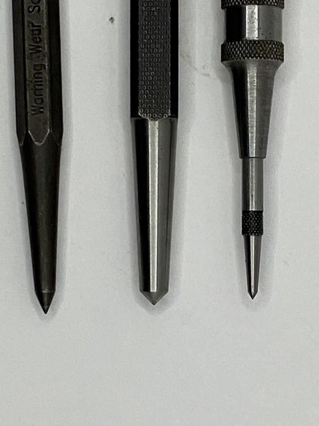
The above photo illustrates the tip grinding on both a prick punch and a center punch. The slender tip taper of the prick punch is designed to allow better visibility and more concentrated pressure when performing layout marking. Contrast the relative shallow taper of the center punch. This hearty tip is designed for creating a larger formed dimple, which will be used to locate a drill bit tip when performing drilling operations. The most common drill bit tip has a 118-degree angle. This angle aids in centering the drill bit and preventing the drill from “walking” out of the center punch dimple.
Author’s Tip
“Walking” or “wandering” is a drill bit’s tendency to want to drill a hole anywhere except where you want it. The rotational motion of the drill will grip the surface of the stock and travel across the surface before the cutting edges have a chance to form a chip. 118° drills tend to do this because those drills have a chisel tip center on them. Center cutting drills, such as those with a 135° drill tip, have cutting edges that come to the center of a drill bit and help eliminate drill bit walking.
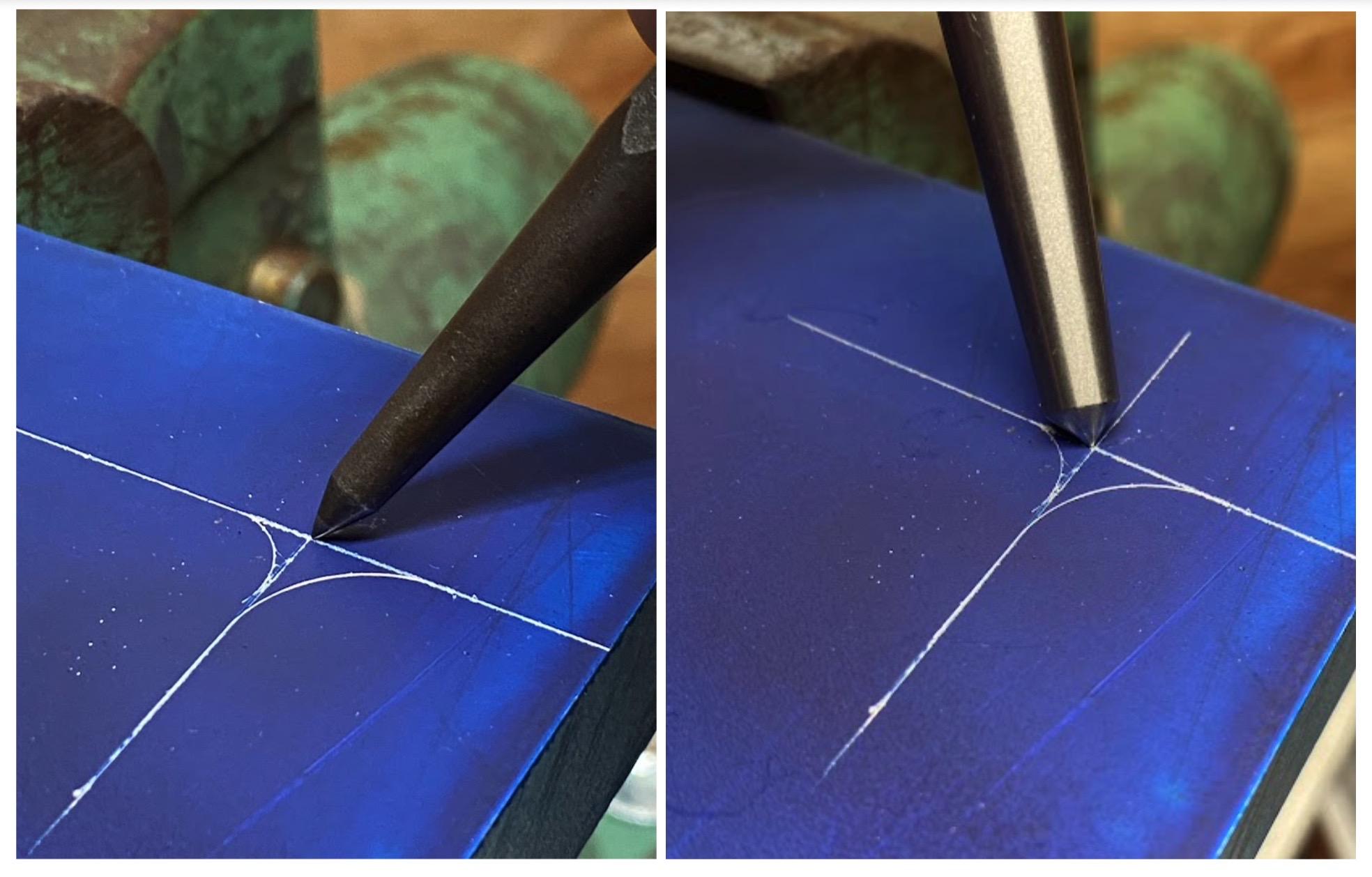
The figure above illustrates the improved visibility of the steeply angled prick punch (left) as compared to a center punch.
How to Center Punch
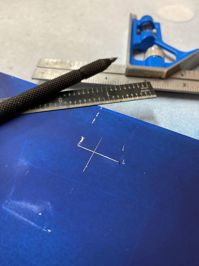
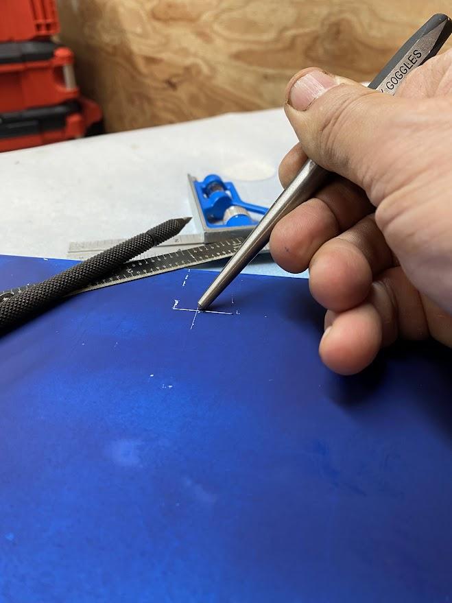
Placing an accurate punch mark with enough depth to align a setup tool point, such as a divider or trammel or for the tip of a drill bit, is an essential skill for a layout technician to perform. Below are steps for the proper application of a prick punch.
Automatic Center Punch
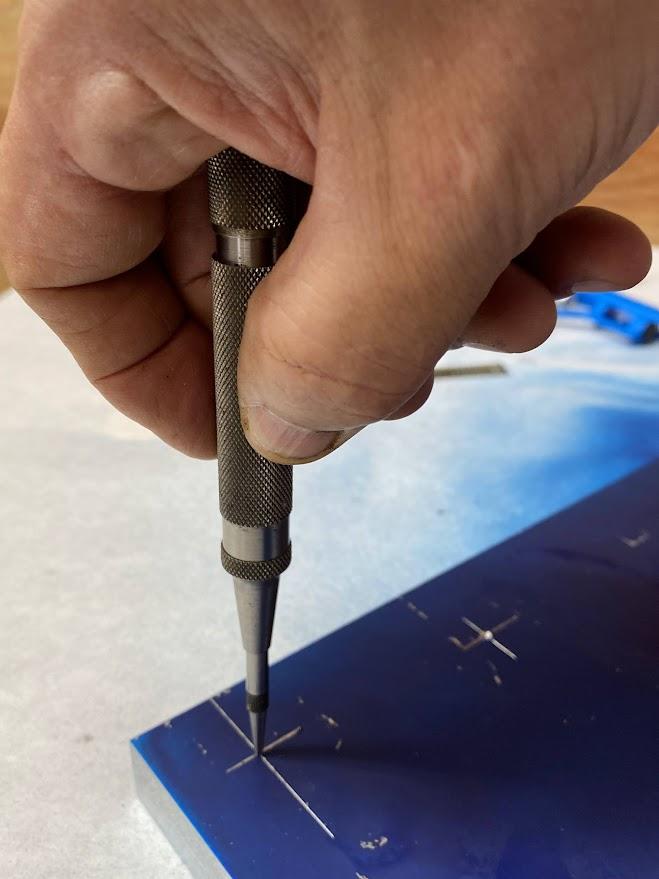
Automatic center punches are spring-loaded tools used to create center punch marks. When you press the handle of an automatic center punch, it compresses the spring inside. The spring stores energy and releases it to drive the punch into the workpiece. Repeated strikes of the automatic center punch will create a larger mark. Some find the automatic punch to be more accurate than hammer driven center punches due to the tendency to strike the hammered punch off center. If necessary, a hammered center punch can be used to enlarge the strike mark of an automatic punch. Due to the well positioned automatic center punch mark, this approach reduces the likelihood of the tip departing from the mark when hammered.
Attributions
- Figure 5.43: Automatic center punch, center punch, prick punch by Damon Donner, for WA Open ProfTech, © SBCTC, CC BY 4.0
- Figure 5.44: Prick punch and center punch tip angles by Damon Donner, for WA Open ProfTech, © SBCTC, CC BY 4.0
- Figure 5.45: Prick punch and center punch aligned on layout lines by Damon Donner, for WA Open ProfTech, © SBCTC, CC BY 4.0
- Figure 5.46: Mark the material with an “X” where the punch will be located by Damon Donner, for WA Open ProfTech, © SBCTC, CC BY 4.0
- Figure 5.47: Align the punch tip with the center of the “X” by Damon Donner, for WA Open ProfTech, © SBCTC, CC BY 4.0
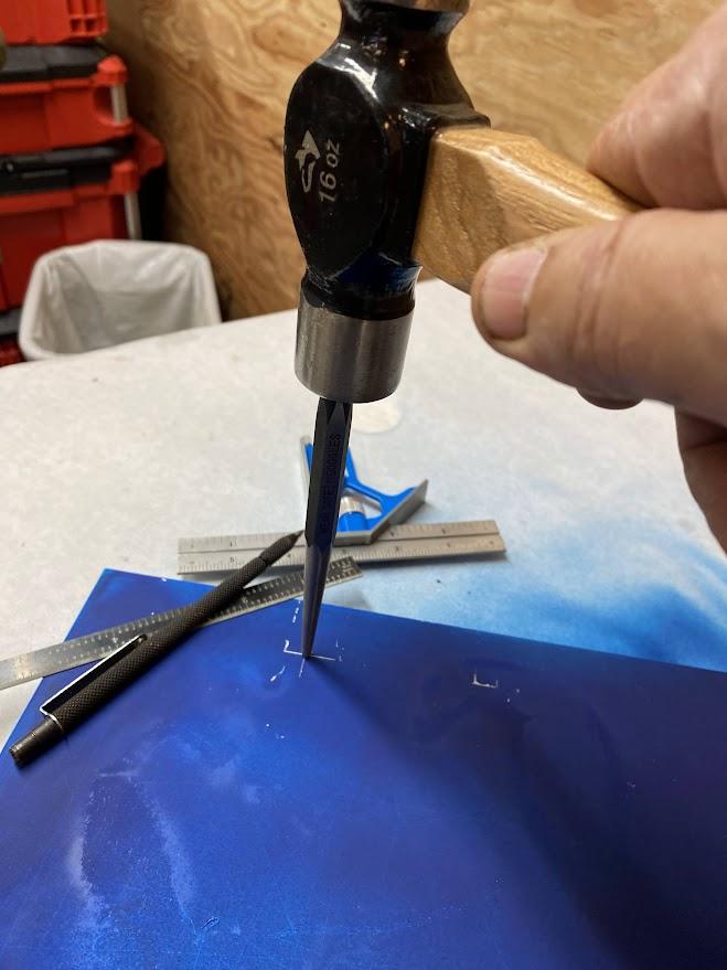
- Figure 5.48: Strike the upright punch with a hammer by Damon Donner, for WA Open ProfTech, © SBCTC, CC BY 4.0
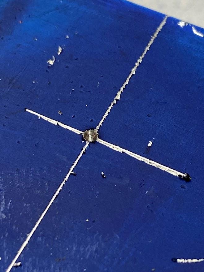
- Figure 5.49: Remove the punch and check your mark by Damon Donner, for WA Open ProfTech, © SBCTC, CC BY 4.0
- Figure 5.50: Automatic center punch by Damon Donner, for WA Open ProfTech, © SBCTC, CC BY 4.0
form tools with conical ends designed to be struck with a hammer, leaving a dimple on the stock material
are spring-loaded tools used to create center punch marks.
