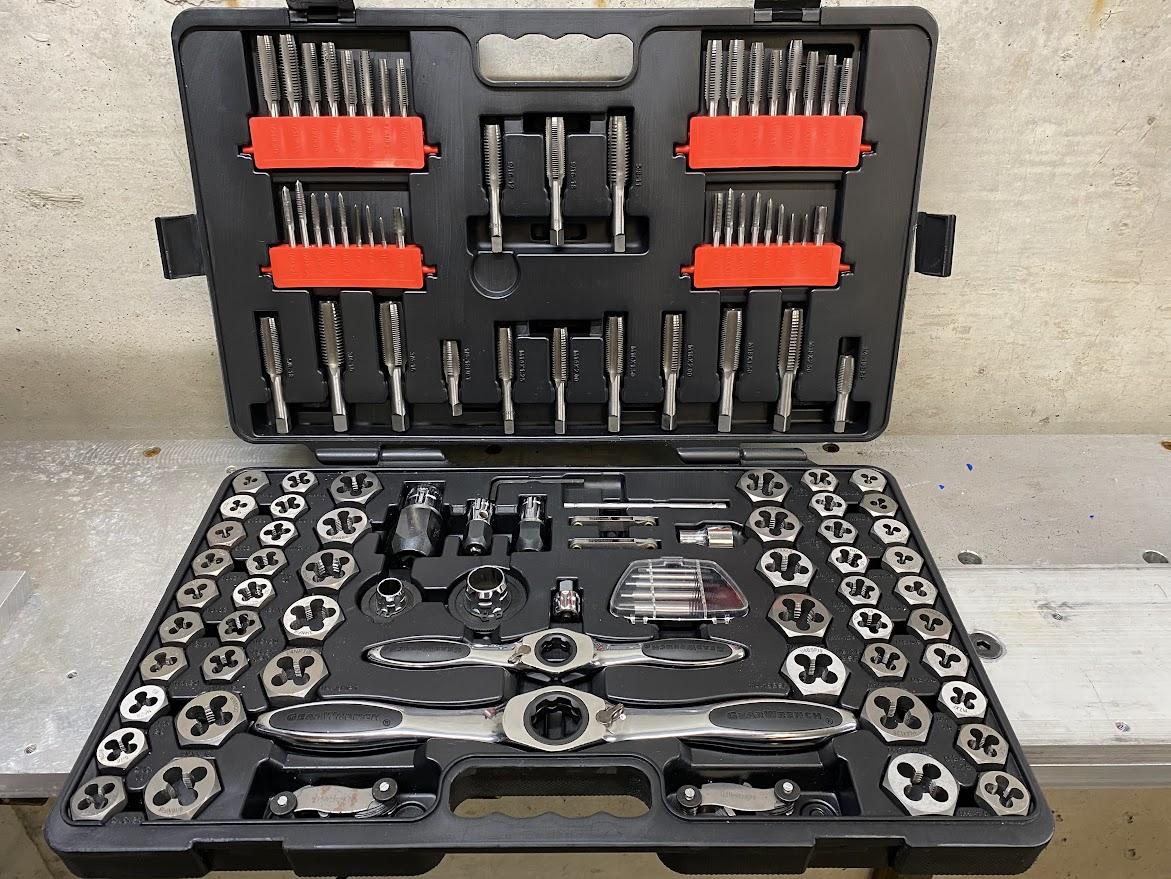
5.9 Tap and Dies
D.M. Donner
Tapping Threads
Cutting threads by hand is considered benchwork because it can be performed without machines. Using a hand drill to create the correct size hole, a machinist can make threads in many different materials. Threads are used primarily in fastening and motion.
The action of creating internal threads in a drilled hole is termed thread tapping. A thread tap is the tool used to create internal threads. The term we use for performing this operation without the use of machines is hand tapping. The processes performed by hand are the same as those used when tapping with a drill press, mill or lathe, but the machinist’s skill and technique determine how well the thread will perform. Using a drill or mill to create a hole is rather simple. The work is held rigid in a vise, and the drill bit is secured in the selected tool holding while the machine castings keep both systems perpendicular (at right angles) to each other. This positioning is essential to creating effective threads and it can be difficult to achieve this when hand tapping. Also, the force provided by machine equipment is substantially more than that on a hand drill. Another challenge for the hand tapping machinist is keeping the drill bit in place until a hole start can be established. The ability to do this task well is important if you want to prevent the drill from wandering across the surface of the material. So, as you can see, secure handling and applying adequate force are important skills for the machinist doing hand tapping work.
To overcome the challenges of hand tapping, we must employ solid technique.
Layout and Punch
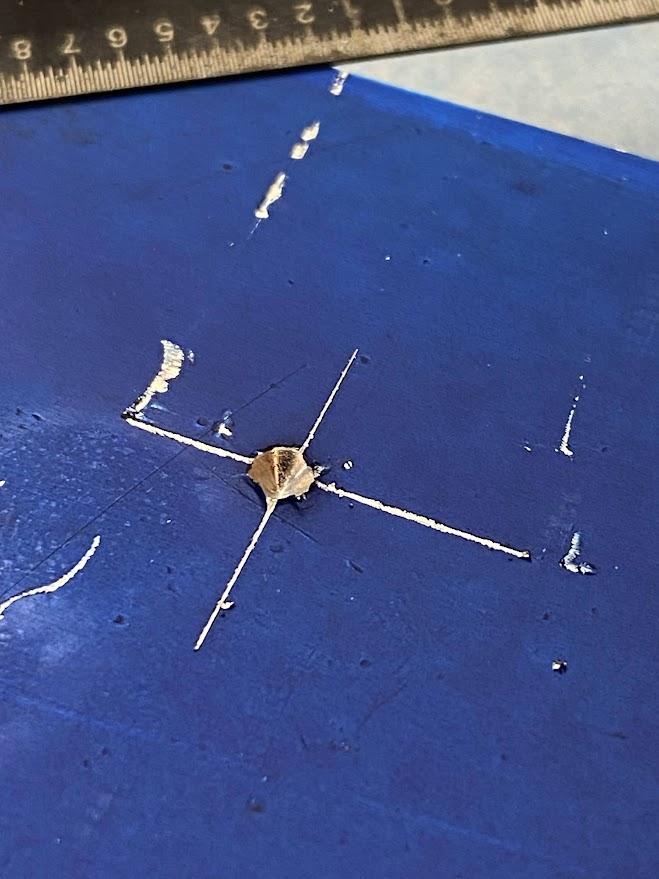
Hand tapping requires the use of layout lines to accurately position the hole since we do not have the scales of a machine’s control surfaces to guide us. To prevent the drill bit from wandering during the drilling operation, we must first center punch the location with a deep punch mark. This center punch mark will create a dimple in the work surface which the drill tip can locate, remaining in place when the surface is turned.
Tap Drills
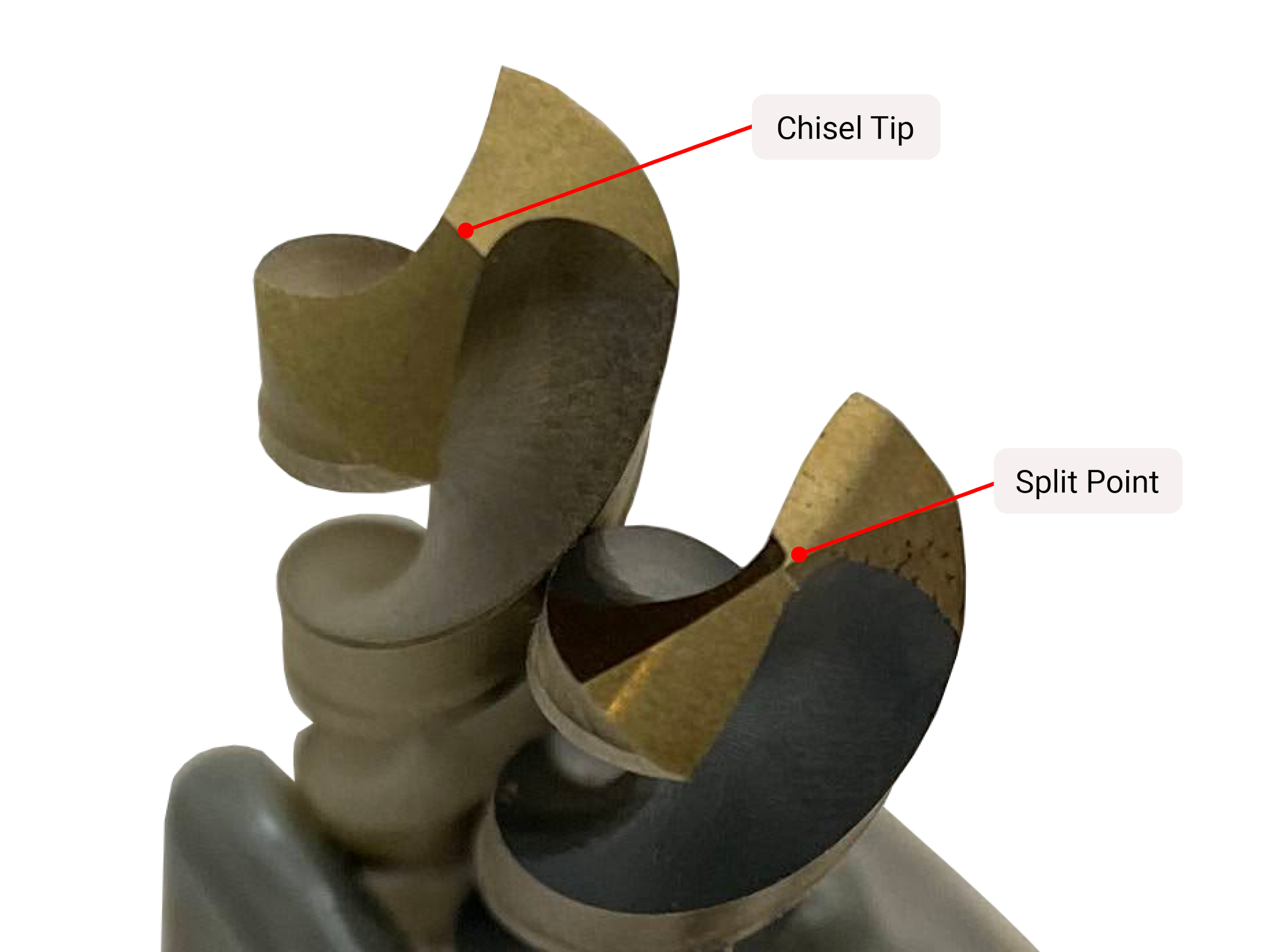
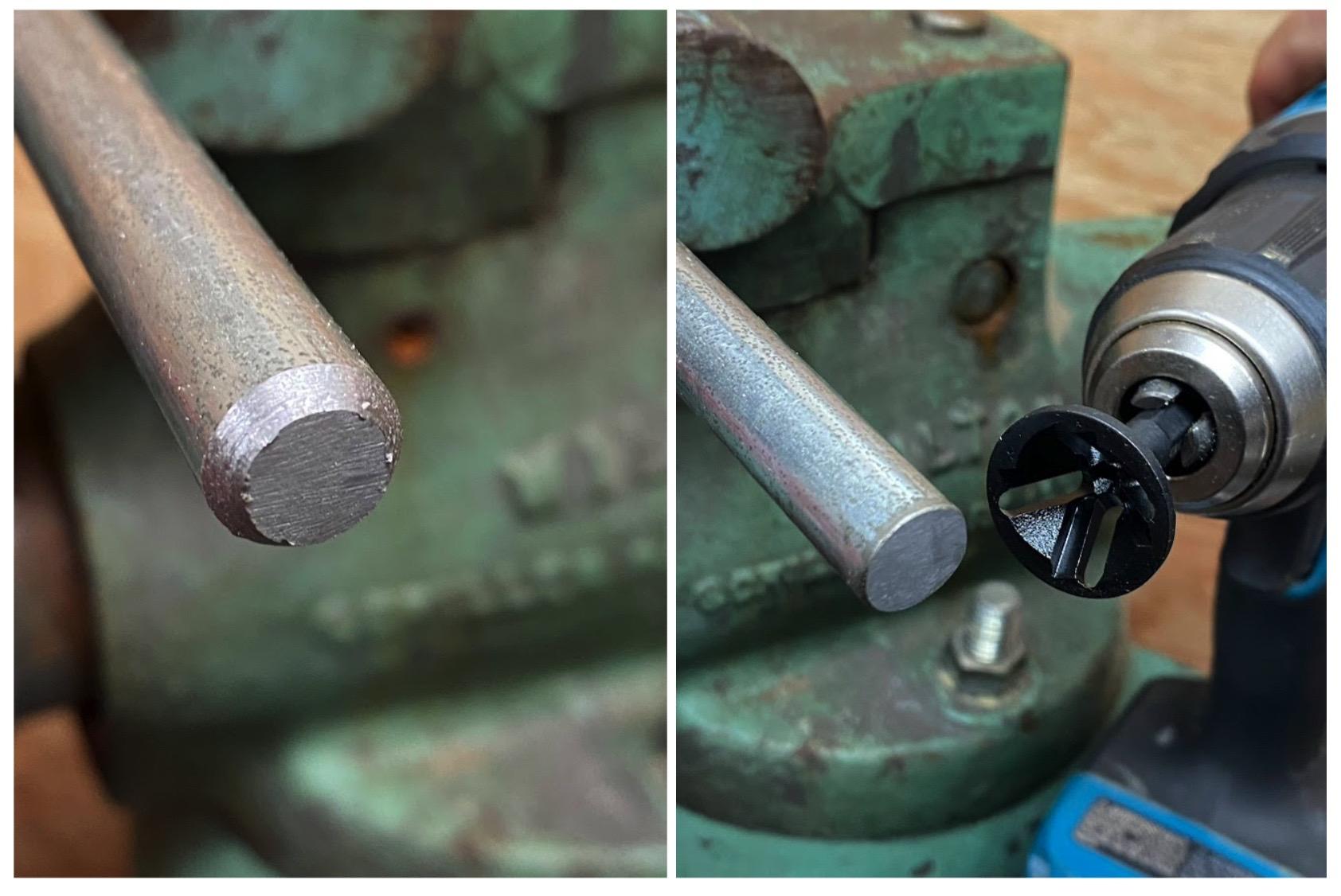
Selecting the correct drill bit tip will help keep the bit from wandering. The most common drill bit point, illustrated on the left in the figure above, is a 118° drill bit. This drill bit is not desirable for tapping because it produces a chisel tip grind. On a chisel tip grind, the center does not make a chip but instead displaces material similar to a cold chisel (chisel used for metal).
What we need is the center cutting drill tip illustrated on the right in figure 5.64. This 135° drill tip has a web thinning grind which means the cutting edges come all the way to the center of the drill bit forming a split tip. This feature works by grinding on the back side of the cutting lips removing material to create the small, exposed cutting edges. This center cutting drill tip will aid in preventing drill bit wander.
The proper size bit for a tap is referred to as a tap drill. To select a tap drill, the machinist can either use a tap drill chart or calculate the drill size. This method is for 75% engagement cut threads only. 75% engagement threads refers to the allowance between the male threads of a bolt and female threads of a nut and is the most common for cut threads. Cut threads remove material by creating a chip. This is in contrast to form threading. Form threading does not cut the material but instead forms or pushes the material by exerting forces against the it. Form tapping uses different tap drills than cut threads and is beyond the scope of this text.
To calculate the tap drill needed for a thread, the pitch of the thread must be known. For inch threads, we use the TPI to find the thread pitch, or distance between threads. The thread designation (TPI) defines how many threads are in one inch and we need to know the distance between each thread. To find thread pitch, divide the one inch by the total number of threads in that inch (TPI). Once we have the pitch of the thread, subtract the pitch from the thread nominal size (¼”, 5/16″, ⅜”…) and this is the tap drill necessary for that given thread.
For a ½-13 UNC thread the 13 is the TPI and one inch divided by 13 is .0769″. (1 / 13 = .0769″)
The nominal size for a ½-13 UNC is ½”. So, the equation is .5 – .0769 = .4231″. Referencing a drill index reveals a 27/64ths drill bit (.422″) is the correct tap drill for this thread.
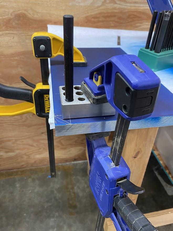
A set of transfer punches is useful for aligning the drill guide with the center punch mark created during layout. A drill guide is a tool that aligns the drill/tap perpendicular to the surface of the stock material. Transfer punches are a type of center punch used to transfer hole locations onto stock material for further operations. They come in a fractional set similar to drill bits. In the figure above, the center punch feature on the transfer punch is aligned with the layout center punch, and then a clamp is applied to the drill guide to maintain the aligned relationship.
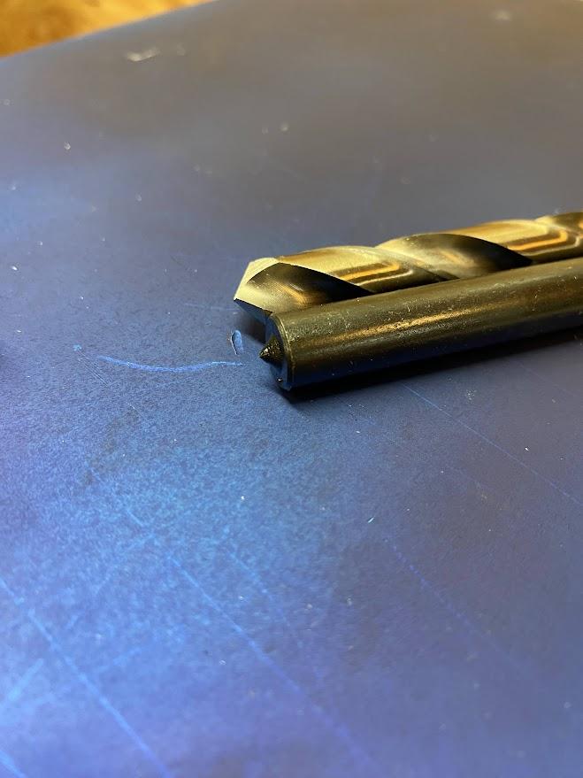
The figure above is a transfer punch next to the drill bit used for the hole. Notice the center punch feature on the end of the transfer punch. A transfer punch is a tool that is designed to be struck with a hammer and transfer the hole’s center point onto stock material, but here we are using it to align our tap and drill operation.
Tap Drilling Operation
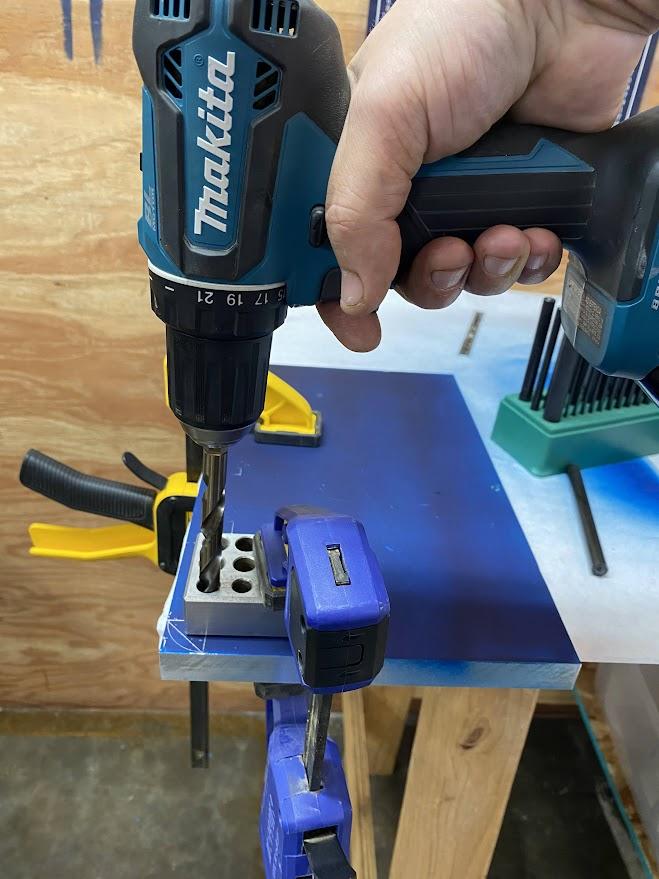
When you are finally ready to drill the hole, the drill bit must be held perpendicular to the work surface to ensure the hole will also be perpendicular. If the hole is drilled at an angle, the fastener screwed into the threads will not perform to the full strength of the threads or fastener because of this angle.
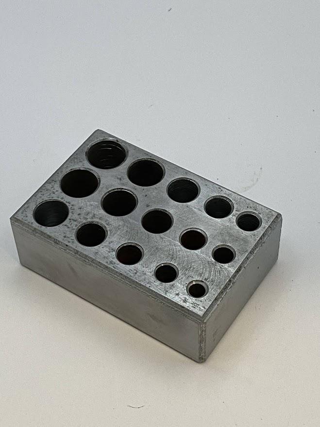
A drill guide block (figure above) is a tool with pre-sized holes that fit the drill bit diameter and is made from a material that can withstand the forces created when turning a drill bit. Clamping the drill guide to the work surface will aid in ensuring the block is not pushed around by the drilling process.
Add a bit of cutting fluid to the tip of the drill and apply enough pressure to the drill to produce a curled chip while drilling. If a chip does not form (resulting in slivers), first ensure the drill is set to the forward direction, then apply more force downward on the drill.
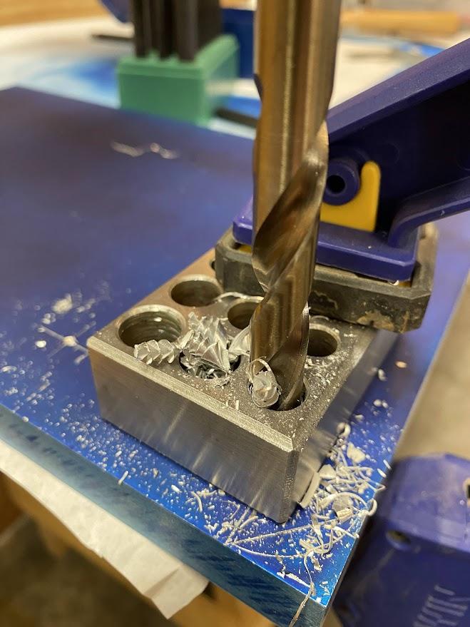
A lack of chip formation during drilling indicates not enough pressure or a dull drill bit. In the figure above, notice the long curly chips. This tells us that the cutting edge is slicing the material correctly. Slivers or small flakes indicate improper chip formation, possibly due to a lack of downward pressure or a dull drill bit. If the drill tip is dull, replace or sharpen the tip and proceed. When the drill tip approaches the other side of the material, it may begin to grab as the tip is pushed through. This can twist the drill body in your hand, causing injury. Reducing downward force at this point can help prevent harm.
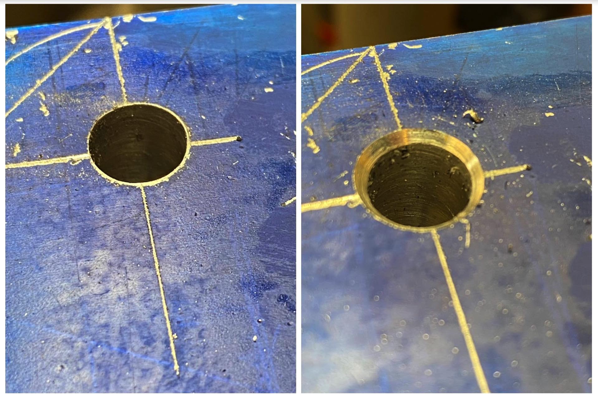
Once the tap drill hole has been created, the top of the hole needs to be chamfered to establish the profile of the first thread. Thread hole chamfering is the process of creating a taper on the top side of a tap drill hole to permit complete thread formation in this critical area. This is an important step, as the first thread is used to align the fastener threads to prevent cross threading. Cross threading is when a fastener’s threads do not follow the threads they are inserted into but rather cross over the existing threads, creating a situation that destroys both sets of threads.
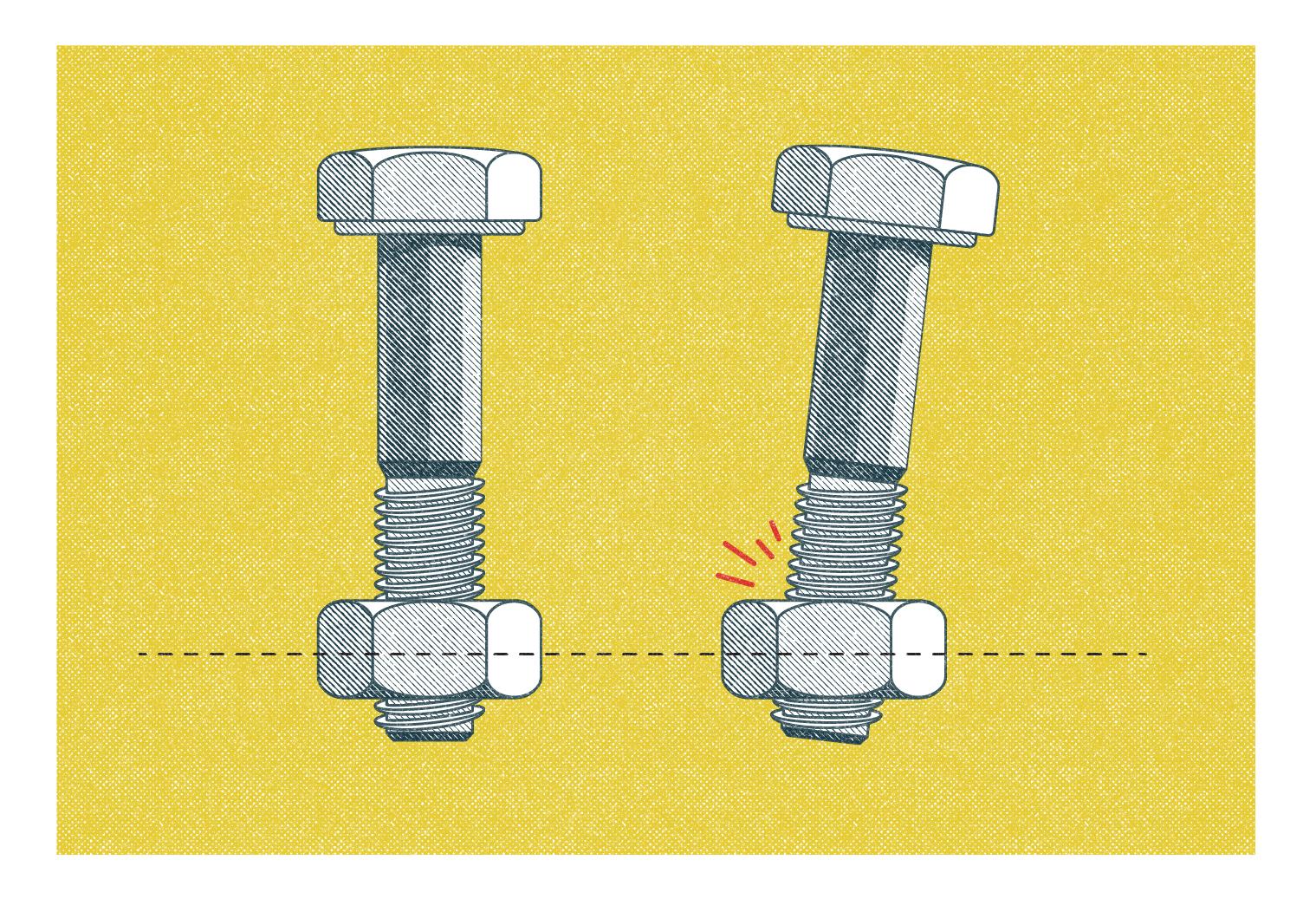
In the image above, the bolt on the left is threaded correctly. Notice that the bolt is perpendicular to the top of the net. The bolt on the right is at an angle and is engaging the threads incorrectly, resulting in stripped threads.
Author’s Tip
Always start a fastener by hand so you can feel when misalignment occurs. Never start a fastener with a wrench or powered drive, such as an impact wrench.

Choose a Tap
We now have a properly located hole, drilled to the correct size, and the first thread chamfer has been added. We can now tap threads into the hole and to do this we must understand the different types of taps. The figure above shows three hand taps. It is important to note that these are intended for hand tapping and not power tapping. Power tapping is when the tap or material being tapped is turned by a machine’s spindle. The machine exerts force on the cutting edges which the hand tap was not designed to withstand, and such force can lead to broken taps. A broken tap creates problems that are not easily solved and often require starting over.
Hand Taps
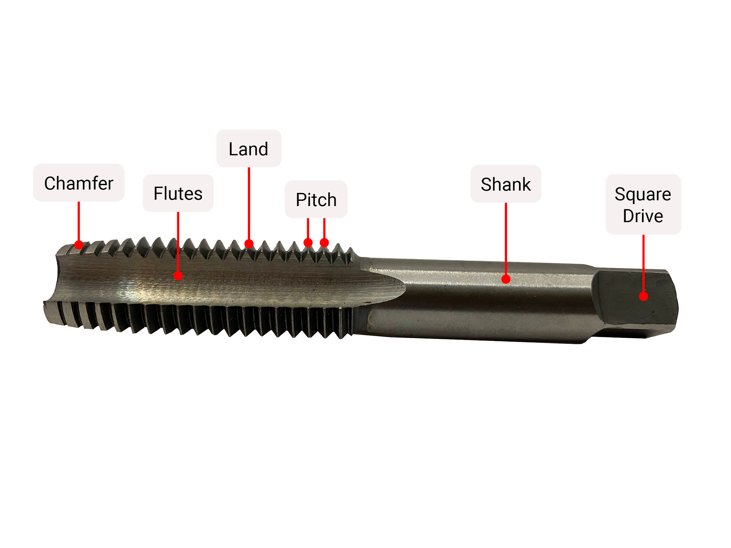
Figure 5.73 shows the parts of a simple hand tap. This is the most basic tap, and a general understanding of what the parts do is important.
The tap chamfer assists in guiding a tap into the tap drill hole to prevent misalignment. The taper chamfer performs this task best, and all threads are started using the taper chamfer if available and able to fit into the tap drill hole.
Tap chamfer refers to the first series of threaded lands at the beginning of the tap. For hand taps, there are three basic types of chamfer intended for different purposes.
Tap lands are the location on a tap where cutting edges are ground, and they create the chip by slicing the material away. The distance between the tips of the lands is called a thread pitch. Thread pitch gets more complicated on multi-start threads but for single start threads, which we are discussing, pitch will be the distance between thread tips.
Tap flutes is the space between tap lands that provides room for cut chips to accumulate during tapping. Accumulated chips interfere with the tapping process if their length is not managed.
Tap shanks control the reach of the tap due to their varying lengths. Specialty taps such as “pulley taps” have extended length shanks to prevent interference during the tapping operation.
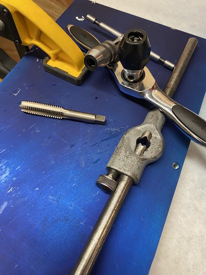
Square drives are the attachment point for tooling used to rotate the tap during operation. Dedicated tap wrenches adjust to fit varying drive sizes and have handles that provide mechanical advantage to the operator.
Hand Tap Chamfers
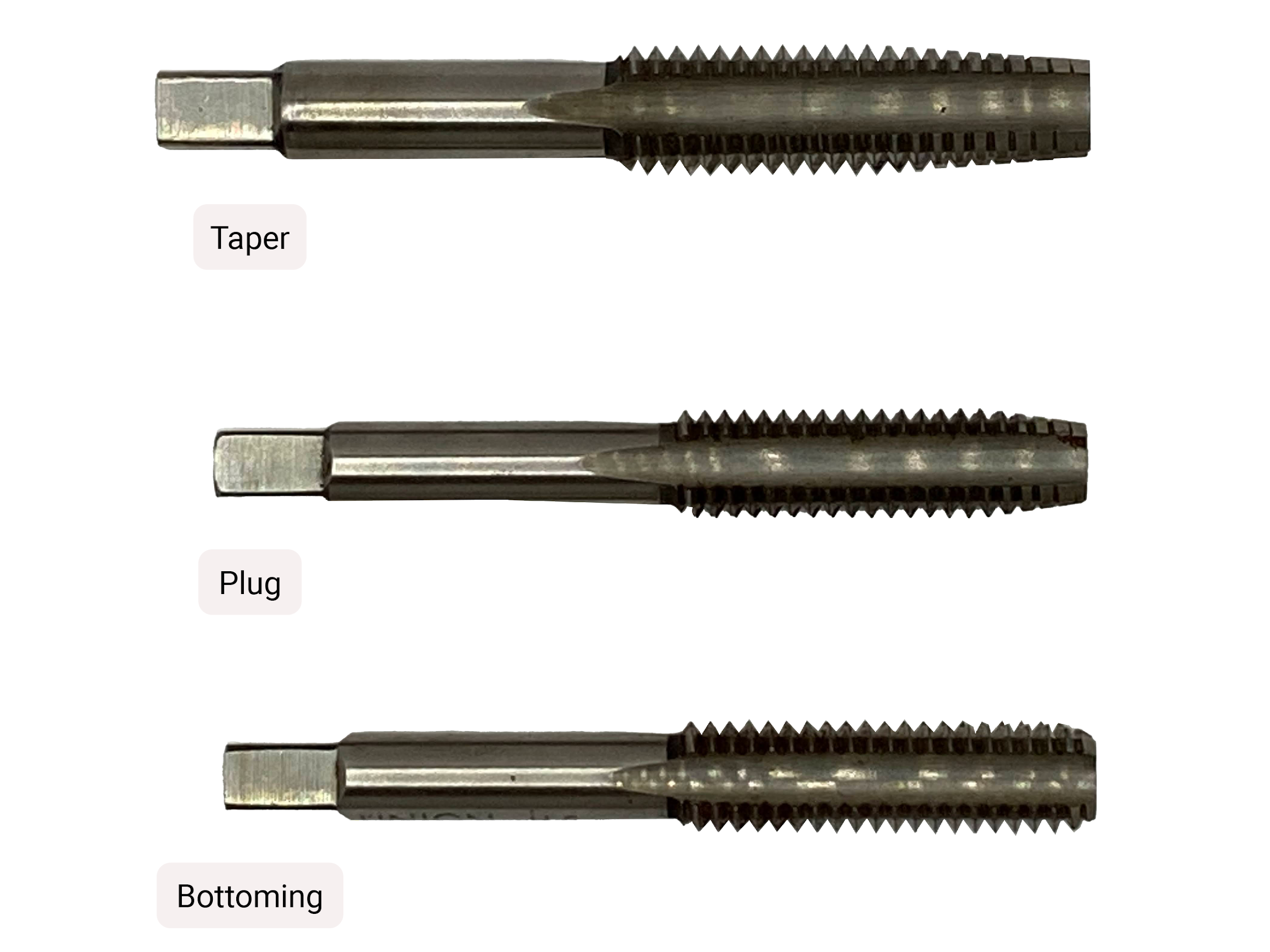
Hand taps have a series of partial threads on the end, and the diameter tapers within this area of partial threads. It is this region that determines what type of hand tap it is.
The taper tap, also known as a starter tap, has the longest taper, 7-10 threads, which acts as a guide to assist in keeping the tap perpendicular when starting a new thread. This tap can be used on thru holes where the threads exit the far side of the stock.
The bottoming taps have the shortest chamfer and the least number of partial threads, 1-2 threads, and are designed to thread blind holes that do not exit the other side of the stock but allow the most full threads possible.
Between these two extremes is the plug tap. This tap has a medium taper of 3-5 threads, is a good general purpose hand tap, and is the most common. Depending on the situation, this tap can thread both through holes and blind holes if the hole depth is deep enough to have 3-5 incomplete threads.
In practice, we would use at least two of these taps for most applications. The taper tap is used first to ensure threads are started square to the surface. Then, either a plug tap for through holes or a bottoming tap for blind holes is used.
Tapping Operation
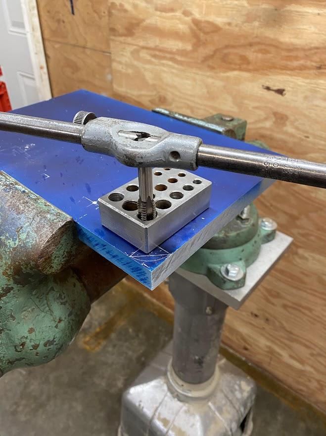
A taper tap is selected, and a tap guide is used to align the tap perpendicular to the tap drilled hole.
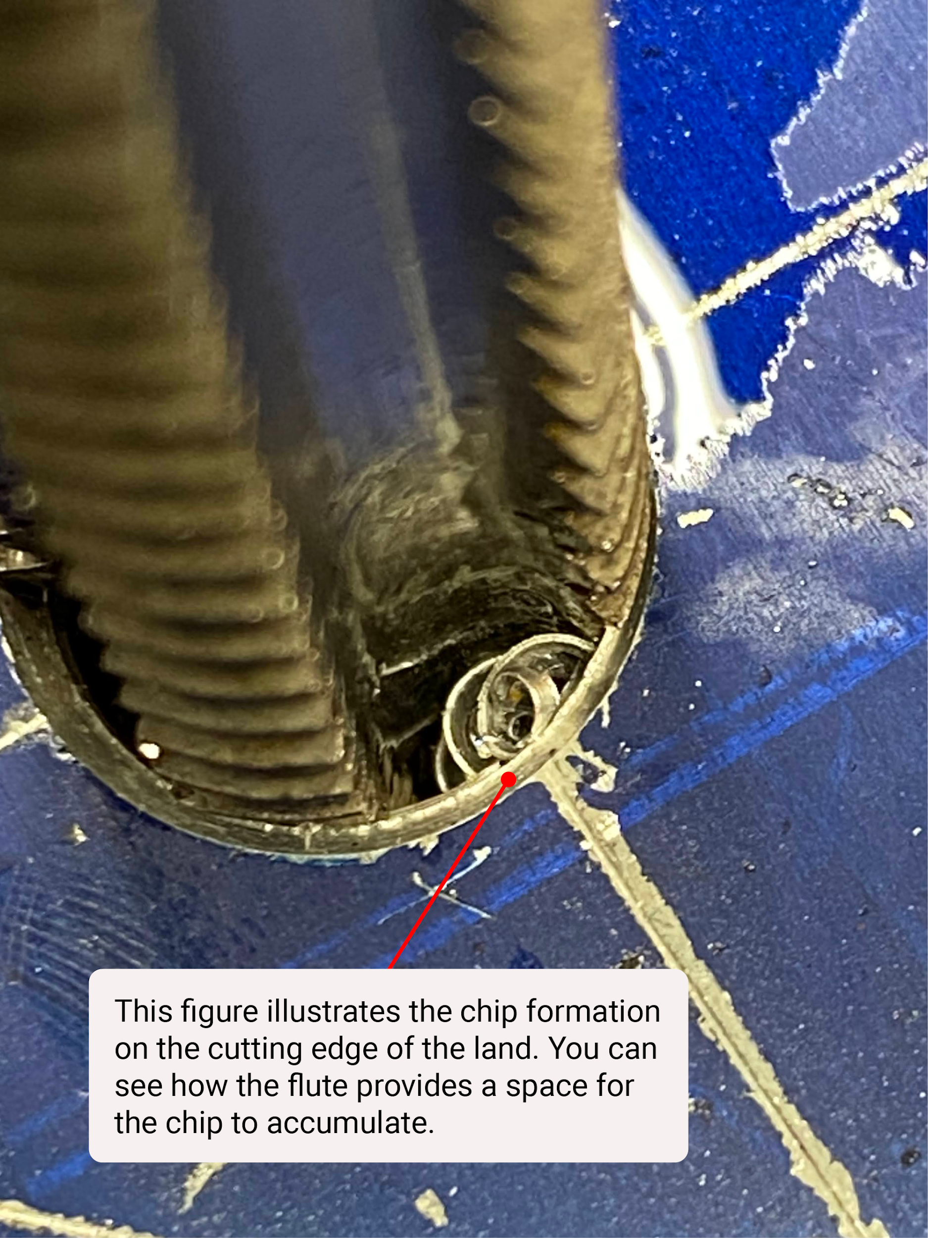
While the flute allows space for chip formation, excess chips will bind the tap requiring excess pressure to turn the tap. To control chip length, the operator must stop after every half turn of the tap handle and break the chips free. This is performed by rotating the tap handle backwards (counterclockwise) until you feel the chip break loose and fall from the flute. In the figure above, the chip is against the back of the cutting land, and rotating the handle further breaks the chip loose keeping it from interfering with the tapping operation.
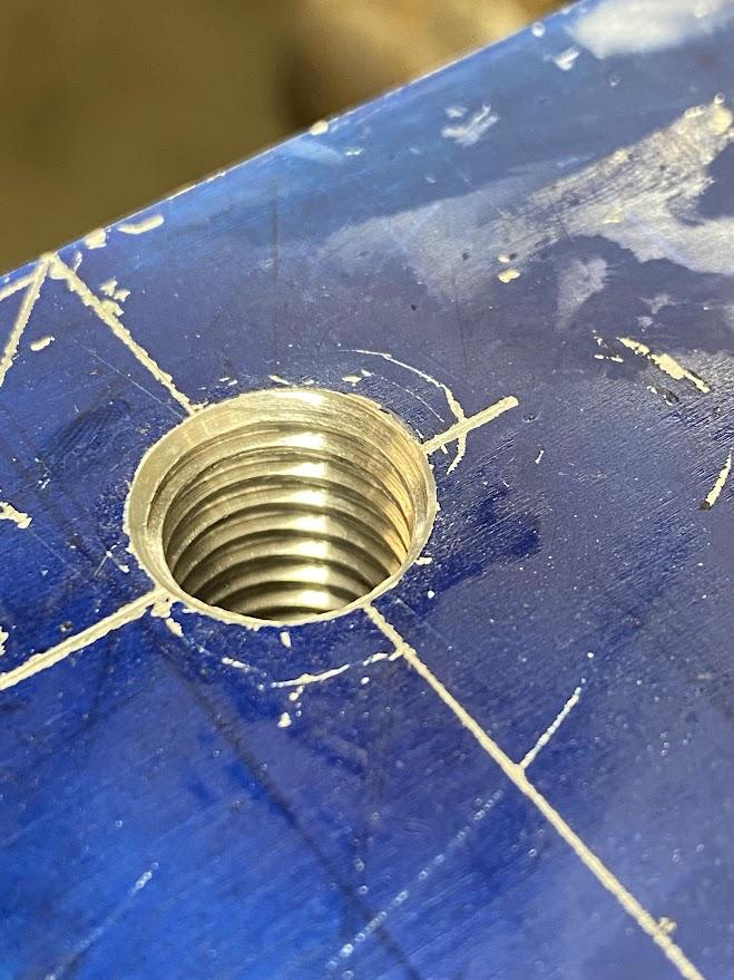
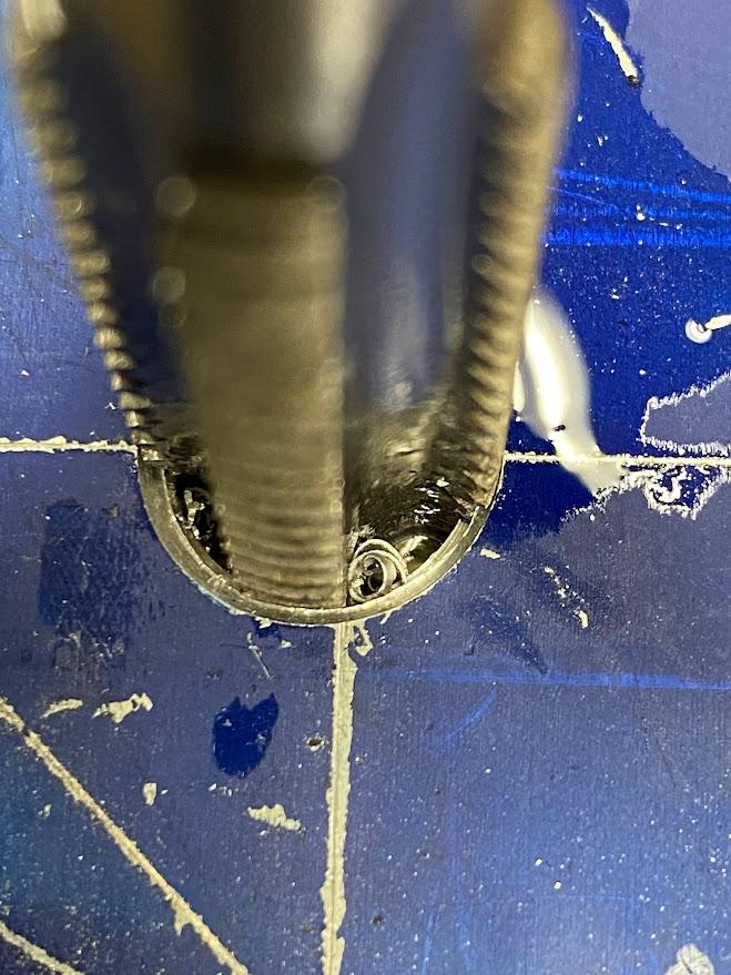
The figure above illustrates a finished tapped hole. The first thread chamfer allows for a complete profiled thread at the top of the hole which will help prevent cross threading.
Thread Dies
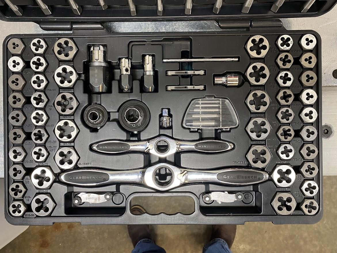
A thread die is a tool used to create external threads on a cylindrical workpiece, such as bar stock or a pipe.
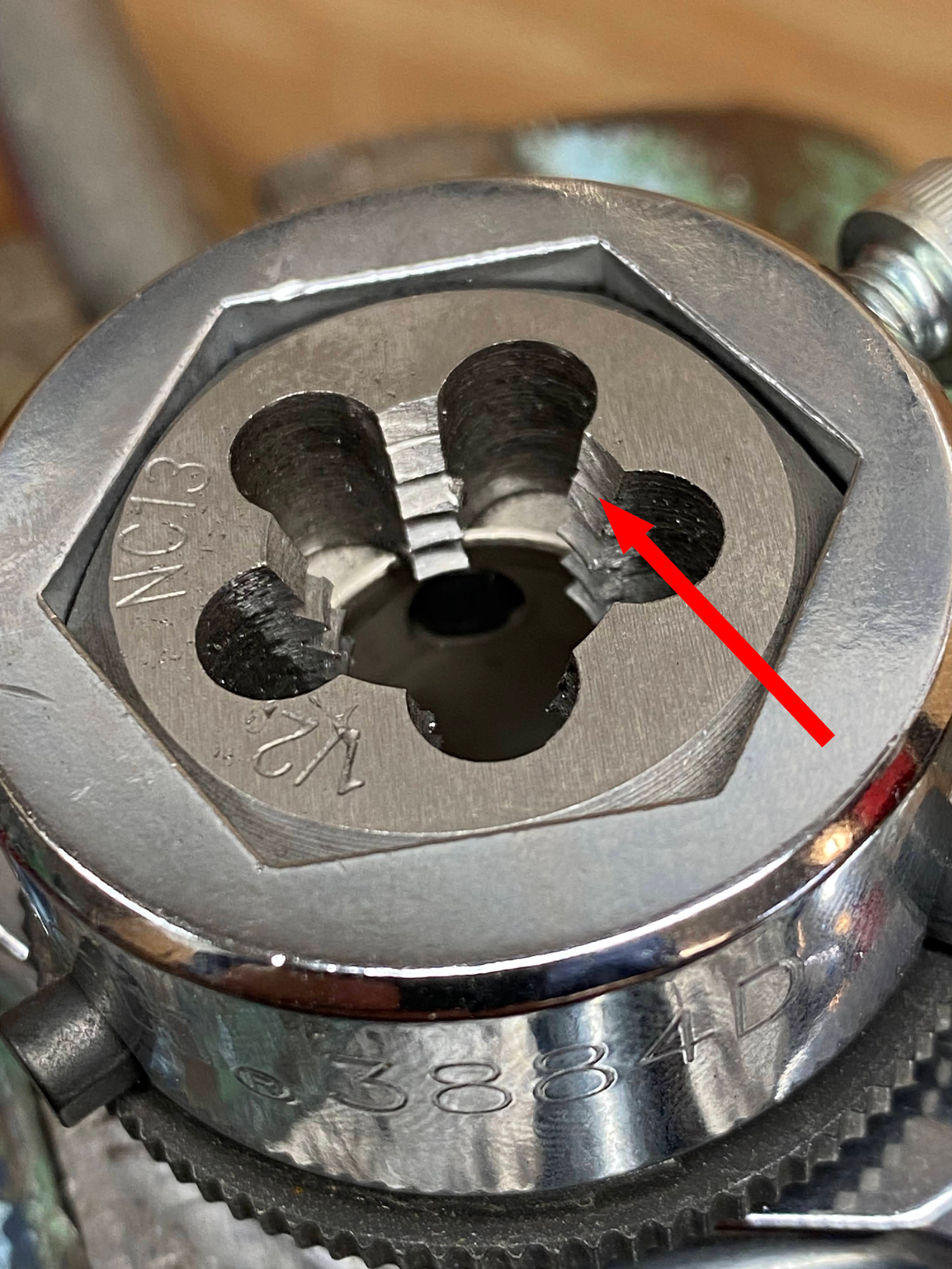
Die bodies come in various shapes and sizes to accommodate the thread size and tool used to operate the die. In the example above, the die body is hexagonal (six sided) and requires a holder of the same form. One side of the die will have a chamfer (illustrated above) to allow the die to align with the bar stock.
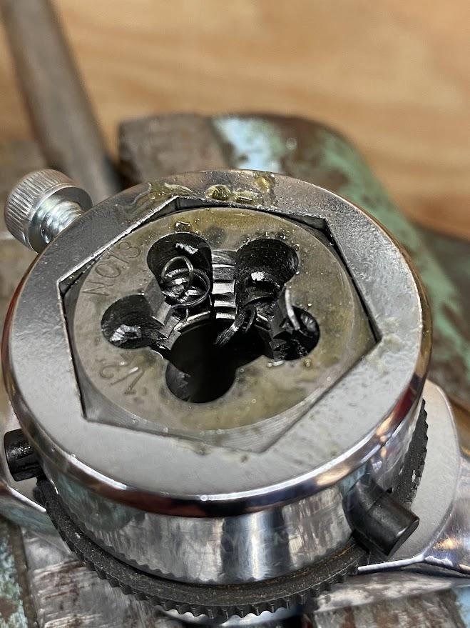
Threading die have flutes that provide space for chips to accumulate during the threading process.
Die Threading Operation
To prepare the end of the round stock to receive a thread, a chamfer must first be created. This chamfer will create a full first thread allowing a better fit for the die chamfer to engage the stock material.
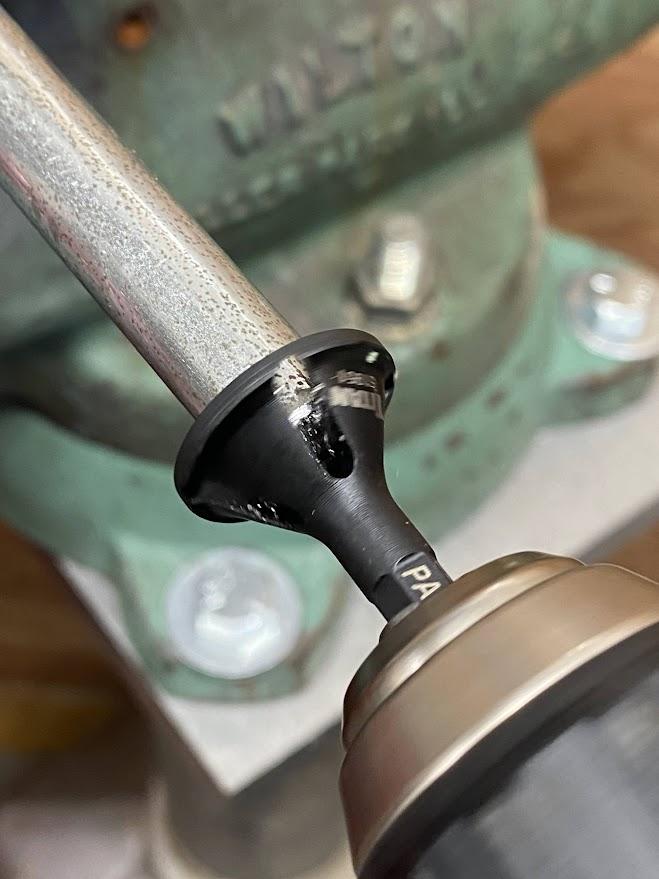
In figure 5.84, a drill motor is used to turn the chamfer tool. Chamfer tools are made from tool steel and heavy force is required to create a cut on mild steel.
A large chamfer is needed to create a surface that the threading die can engage. This is because benchwork operations lack the forces of machining equipment such as lathes and mills.
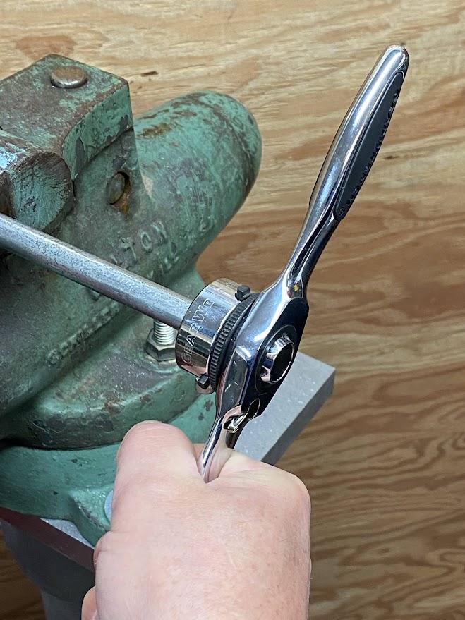
The figure above illustrates the die handle assembly being kept perpendicular to the stock axis to ensure straight threads are formed. On the ½” low carbon steel above, a very large chamfer had to be cut in order to start the die by hand.
It takes two hands to turn the die handle clockwise to cut the threads. Just like when cutting tapped threads, the machinist must stop every half turn and break the chips loose. This cut and break process continues until the threads are cut to the required length.
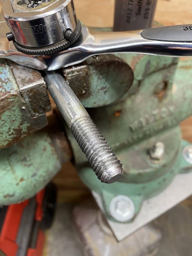
After the thread depth has been reached, the die is removed and inspected. The thread profile may need to be dressed with a file to clear any burrs created during the threading operation.
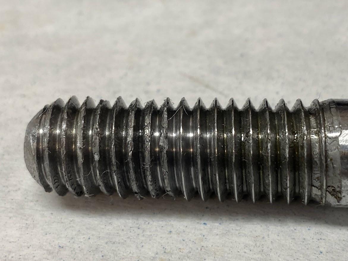
Notice the contrast in thread quality in the figure above. The threads at the start of the operation were cut dry (not using cutting oil), and the threads toward the end had thread cutting fluid applied.
Thread cutting fluid lubricates the cut, which reduces stresses created at the cutting edge of a die. Depending on the material being threaded, select the correct cutting lubricant to ensure optimal performance.
Attributions
- Figure 5.62: Tap and die set by Damon Donner, for WA Open ProfTech, © SBCTC, CC BY 4.0
- Figure 5.63: Center punch on layout lines by Damon Donner, for WA Open ProfTech, © SBCTC, CC BY 4.0
- Figure 5.64: Centerpoint of a drill bit by Damon Donner, for WA Open ProfTech, © SBCTC, CC BY 4.0
- Figure 5.65: Aligning a drill guide using a transfer punch by Damon Donner, for WA Open ProfTech, © SBCTC, CC BY 4.0
- Figure 5.66: Transfer punch illustrating the punch type tip by Damon Donner, for WA Open ProfTech, © SBCTC, CC BY 4.0
- Figure 5.67: Holding a drill perpendicular to the surface by Damon Donner, for WA Open ProfTech, © SBCTC, CC BY 4.0
- Figure 5.68: Drill guide block by Damon Donner, for WA Open ProfTech, © SBCTC, CC BY 4.0
- Figure 5.69: Proper chip formation during drilling by Damon Donner, for WA Open ProfTech, © SBCTC, CC BY 4.0
- Figure 5.70: Tap drill hole before and after chamfer by Damon Donner, for WA Open ProfTech, © SBCTC, CC BY 4.0
- Figure 5.71: Proper threads and cross threaded fasteners by Damon Donner, for WA Open ProfTech, © SBCTC, CC BY 4.0
- Figure 5.72: Tap and die set by Damon Donner, for WA Open ProfTech, © SBCTC, CC BY 4.0
- Figure 5.73: Parts of a hand tap by Damon Donner, for WA Open ProfTech, © SBCTC, CC BY 4.0
- Figure 5.74: Tap handle selection for driving taps by Damon Donner, for WA Open ProfTech, © SBCTC, CC BY 4.0
- Figure 5.75: Taper, plug and bottoming tap by Damon Donner, for WA Open ProfTech, © SBCTC, CC BY 4.0
- Figure 5.76: Aligning a tap using a tap guide by Damon Donner, for WA Open ProfTech, © SBCTC, CC BY 4.0
- Figure 5.77: Chip formation during hand tapping by Damon Donner, for WA Open ProfTech, © SBCTC, CC BY 4.0
- Figure 5.78: Chip breaking with a hand tap by Damon Donner, for WA Open ProfTech, © SBCTC, CC BY 4.0
- Figure 5.79: Tapped ½-13 UNC threads by Damon Donner, for WA Open ProfTech, © SBCTC, CC BY 4.0
- Figure 5.80: Thread dies for external threading operations by Damon Donner, for WA Open ProfTech, © SBCTC, CC BY 4.0
- Figure 5.81: Die chamfer by Damon Donner, for WA Open ProfTech, © SBCTC, CC BY 4.0
- Figure 5.82: Die flutes by Damon Donner, for WA Open ProfTech, © SBCTC, CC BY 4.0
- Figure 5.83: Stock chamfer by Damon Donner, for WA Open ProfTech, © SBCTC, CC BY 4.0
- Figure 5.84: Chamfer operation by Damon Donner, for WA Open ProfTech, © SBCTC, CC BY 4.0
- Figure 5.85: Threading die by Damon Donner, for WA Open ProfTech, © SBCTC, CC BY 4.0
- Figure 5.86: Finished cut threads by Damon Donner, for WA Open ProfTech, © SBCTC, CC BY 4.0
- Figure 5.87: Finished cut threads by Damon Donner, for WA Open ProfTech, © SBCTC, CC BY 4.0
The action of creating internal threads in a drilled hole
the tool used to create internal threads.
The proper size drill bit for a tap
the allowance between the male threads of a bolt and female threads of a nut and is the most common for cut threads
remove material by creating a chip. This is in contrast to form threading
does not cut the material but instead forms or pushes the material by exerting forces against the material
a tool that aligns the drill/tap perpendicular to the surface of the stock material
a tool that is designed to be struck with a hammer and transfer the hole's center point onto stock material
The process of cutting an angle on the sharp square corner of a part. The sloped or angled edge between two connecting surfaces of a part. It can be used on either an internal or external edge. The taper placed on the top, inside of a tap drilled hole that facilitates the formation of a complete thread.
the first series of threaded lands at the beginning of the tap
the location on a tap where cutting edges are ground and they create the chip by slicing the material away
The distance a fastener advances with one rotation. For a single start thread, it is the distance between thread tips.
the space between tap lands that provide a space for cut chips to accumulate during the tapping operation
a tool used to create external threads on a cylindrical workpiece, such as bar stock or a pipe
