6.3 Tool selection
Tim A. Bacon
There are numerous tools to choose from when machining a part. To better understand tool selection, it is helpful to divide tools into groups according to their function.
- Face mills and fly cutters will cut large areas.
- End mills and corner rounders cut the outside of parts.
- Boring bars and grooving tools are used to cut the inside of parts.
- Drills and reamers make holes.
- Pattern or form tools cut a specific thread or chamfer.
Initially, the selection of tools will be guided by the type of material being worked on. High speed steel (HSS) tools were used exclusively until 1920. After 1960, the use of carbide tools significantly increased. More on the history of cutting tools can be found on this Tool Grades site (n.d.).
Carbide tools have a long lifespan, and they can endure heat when cutting a part. They are often a good choice. In shops today, there are also a plethora of inserts to choose from. They come in a multitude of finishes and shapes. Tool vendors are typically very knowledgeable and can offer suggestions for productive feeds and speeds for cutting parts.
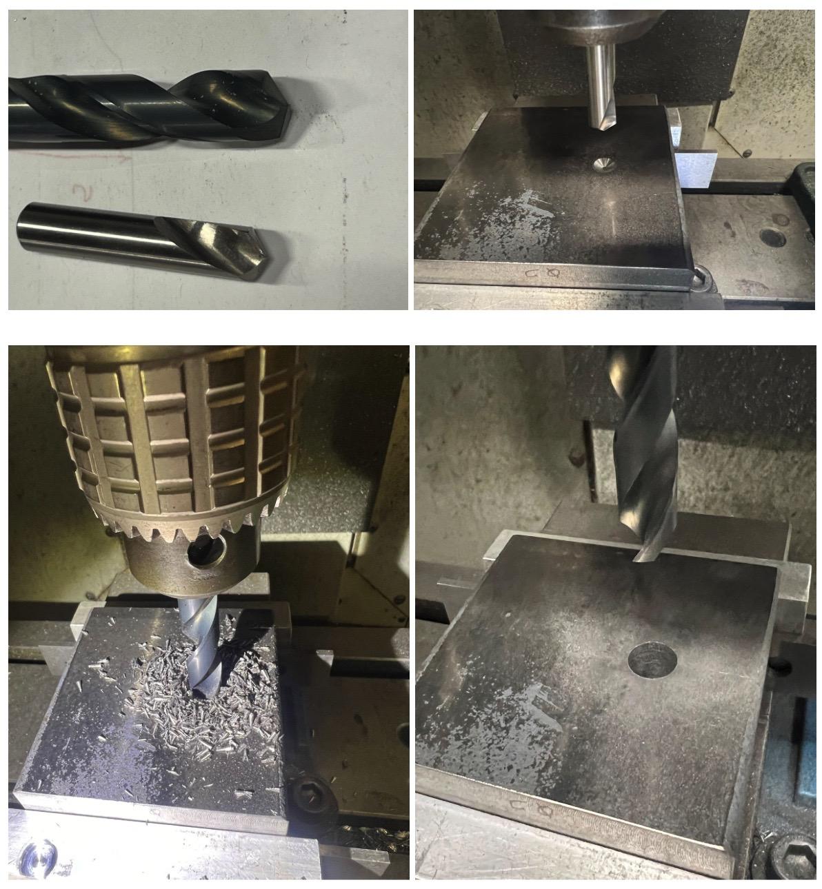
Sometimes, tool selection depends on finish requirements. For example, when making a hole, if a smooth finish is not needed, then just drilling the hole may be adequate. And, if it is a deep hole, the drill may “wander” off of its location. This will require the machinist to straighten out the hole by plunging an endmill into it or using a boring bar to open it up. A reamer can follow the endmill process to open the hole slightly more and attain a good finish.
If a tool is unavailable, alternatives need to be identified, and this happens during the planning process. It is common to find that extra tooling and/or workholding needs arise. The machinist will have to figure out how to accommodate these needs.
Referencing the bench block drawings from section 6.1, we can determine that the tools needed are a spot drill, drills, end mills, boring bars, a pinch knurling tool, and a turning tool. These tools should be listed on the planning sheet shown at the start of this chapter.
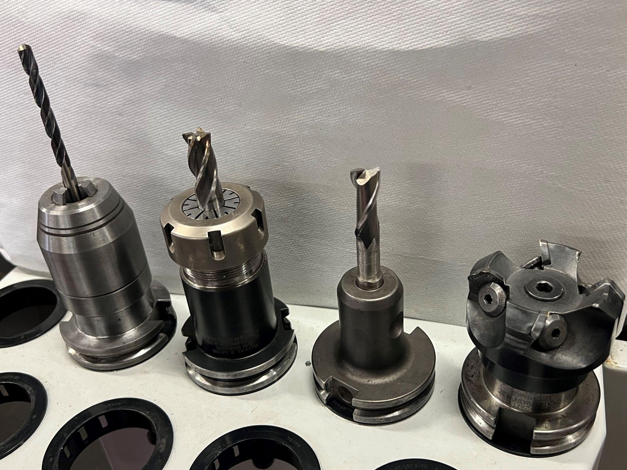
Mill tools
If a hole is needed in a part, a drill is used.
When cutting around the outside of a part, an end mill is used. If a large surface needs to be cut, such as the top of the material, a face mill can be used. For more information on milling and the tools used, refer to Chapter 9.
Tools fall into three subcategories: High speed steel (HSS), carbide, and tools with inserts, also referred to as indexable tools. The HSS tools are susceptible to heat. A ½ inch diameter end mill cutting mild steel will run at 500 revolutions per minute (RPM). A carbide tool can withstand higher heat and higher RPMs. This tool will turn at 1000 RPMs in the same material. The higher speeds will yield higher productivity with an increase in the cost of tooling.
Tools that have carbide inserts have a higher cost when also purchasing the tool holder, but a lower cost when replacing the inserts over time. The RPM of the insert tool will be similar to that of the solid carbide tool in general. All of these accomplish the same thing, material removal.
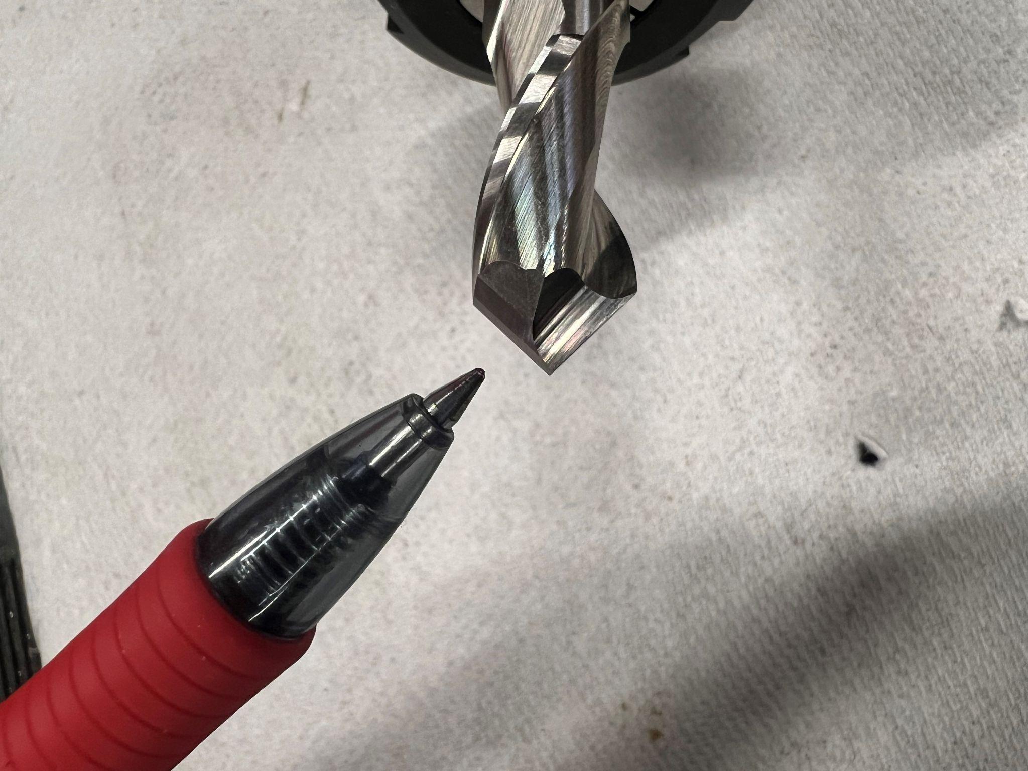
Tools have to be paired with the type of material they are cutting. For tools around 1⁄2 inch in diameter, if cutting steel, then use an end mill with four or more flutes. A flute is the cutting edge of the tool, sometimes referred to as a tooth or teeth when there are more than one. If aluminum is being cut, use an end mill with three or less flutes. A face mill can be used to remove the scale from large surfaces. To save material and keep the part as thick as possible, use the surface grinder (see Chapter 8) to reduce the amount of material removed.
Lathe Tools
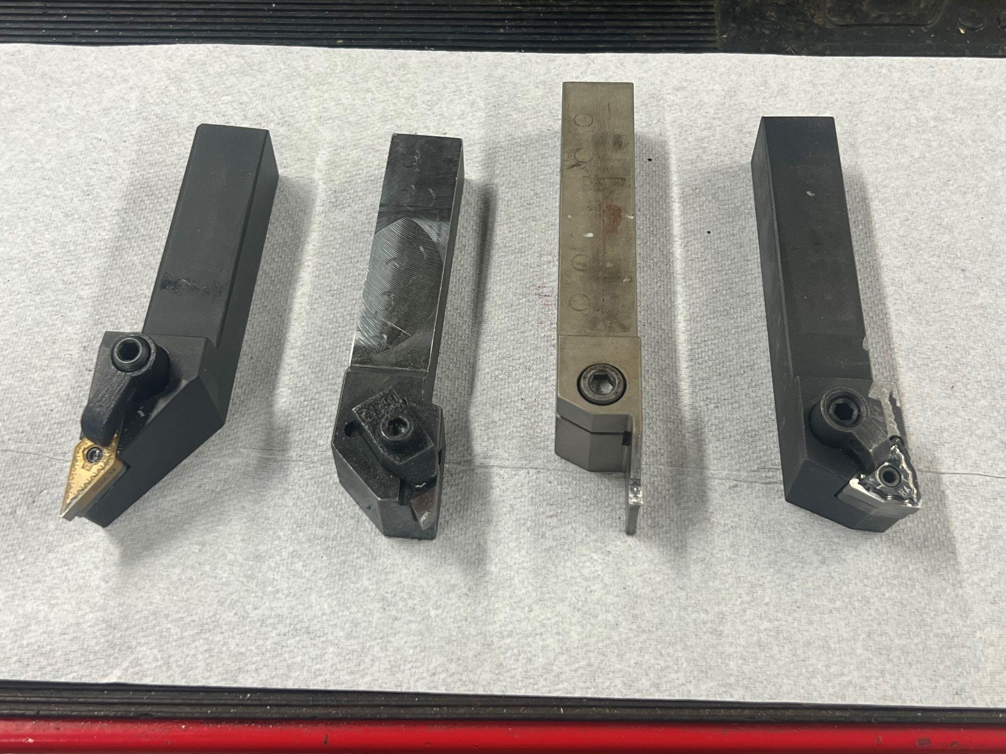
Lathe tools share a common theme but generally have only one point of contact with the part. They make a cut called a continuous cut. This type of cut is less damaging to tools due to the reduced vibration when cutting. Above is a small sample of turning tools. There are also internal tools to create features inside the part.
Our project will use a knurling tool on the left and a turning tool on the right.
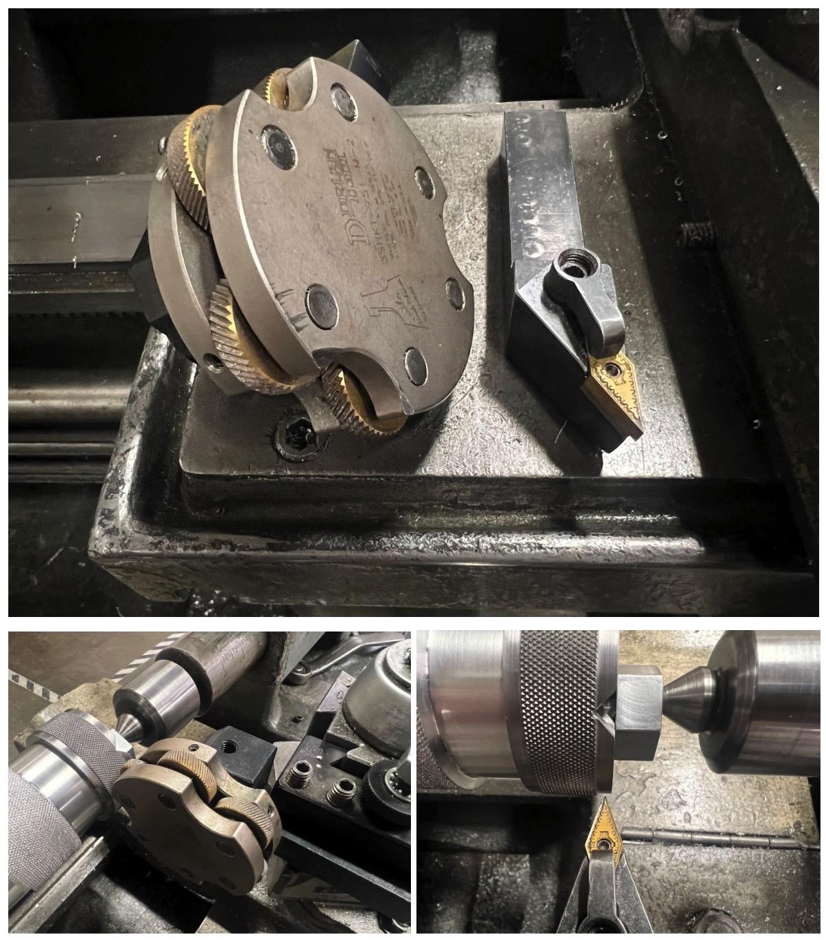
The part will be knurled first. Then the turning tool will cut the relief on both ends. This will provide a clean transition between features. Orient the turning tool so that once it is set up, both sides can be cut.
Attributions
- Figure 6.5: In process drilling by T Bacon, courtesy of Bates Technical College, for WA Open ProfTech, © SBCTC, CC BY 4.0
- Figure 6.6: Milling tools by T Bacon, courtesy of Bates Technical College, for WA Open ProfTech, © SBCTC, CC BY 4.0
- Figure 6.7: Chamfer mill by T Bacon, courtesy of Bates Technical College, for WA Open ProfTech, © SBCTC, CC BY 4.0
- Figure 6.8: Lathe tools by T Bacon, courtesy of Bates Technical College, for WA Open ProfTech, © SBCTC, CC BY 4.0
- Figure 6.9: Turn and knurl by T Bacon, courtesy of Bates Technical College, for WA Open ProfTech, © SBCTC, CC BY 4.0
