6.5 Choosing a machine
Tim A. Bacon
A machine will be selected for its ability to efficiently remove material, and its ability to repeatedly achieve a consistent tolerance. When “roughing out a part,” the majority of material will be removed in the most productive manner possible. To illustrate, grinders are designed to remove around .01 inch of material at the most. This would not be a good machine choice if .5 inches of material needed to be removed. A hobbyist might enjoy just the process of removing material without consideration of timeliness. A paid machinist, however, needs to attend to time being careful to work within project deadlines.
Referencing the picture of the bench block in Section 6.0, you’ll note that it is round. The outside shape of the part being made is called the profile of the part. The sample bench block we are creating is made of 1018 mild steel. This material comes in a flat bar that is band sawed into smaller squares so the machinist can more easily handle the part during production and the material isn’t wasted. If the outside of the profile is cut first, it will be more difficult to hold on to because a circle requires special tooling for workholding. This means if you immediately start cutting a circle out of your material, you will create more work, and the part will take more time to produce. From what we see of the bench block, the vertical mill is the best tool for this project. Again, job planning that includes tool choice leads to greater efficiency. And, efficiency equals profitability.
Machine capability is the level of accuracy a machine provides without user influence. Machine capability varies from one machine to the next. A band saw might be used for the first step in cutting a block of material to +/- .06. But, if the requirements are +/- .01, a table saw might be a better choice because it offers greater accuracy. In making these decisions, machinists need to consider machine capability. When deciding on the machine to use, consider the tolerance requirements and identify a machine that is capable of achieving those results. When machine capability is aligned with technical requirements, productivity increases.
In addition to machine capability, a profitable operation will factor in material usage and conservation. For large quantity jobs, the project plan should include optimization strategies. These strategies are identified after the steps are outlined.
Making 100 of the same part is different from a single part. When the number of parts increases, repeatability and reliability need to be considered. The plan may also shift to one that has batch processing, where a small number of features are cut on all parts before continuing to the next step. This approach is instead of making a complete part before making the next one.
Choosing the right machine for the job requires a comprehensive understanding of the machining process, materials used, tooling, equipment, and the ability to comprehend technical drawings accurately. By meticulously planning each stage of the machining process, potential risks and challenges can be anticipated. This will help to improve productivity, efficiency, and overall success.
A surface grinder can achieve an almost mirror finish with tolerances less than the thickness of a piece of paper (.003). A band saw, mentioned earlier in this book, can cut parts to within 1/16th, or .0625 (spoken as sixty-two and a half thousandths).
We will create a project plan for the bench block to be made with manual machines because we are only making one. If we had to make 100, we might want to automate the process by using CNC machines.
Choosing a CNC mill over manual machines is based on the need for large quantities, high precision, and repetitive actions. Typically, when bidding on jobs, the greater the technology of the equipment, the higher the cost to the customer. If the part can be made by manual machines, the cost to the customer could be $150 per hour. If a CNC mill is used, the customer might be charged $500 per hour. Machines that have automation or are controlled by computers are capable of running more efficiently with higher, more consistent accuracy and this costs more.
Outside processes, sometimes referred to as secondary operations, are a consideration when planning. A machinist might need to leave a part partially finished awaiting secondary operations. In this case, material is purposely left on to be removed later. The part is then sent out for heat treating to improve the characteristics of the material, such as hardness. Upon returning to the shop, the rest of the material is removed. Some other secondary operations are painting, anodizing, and polishing.
Attributions
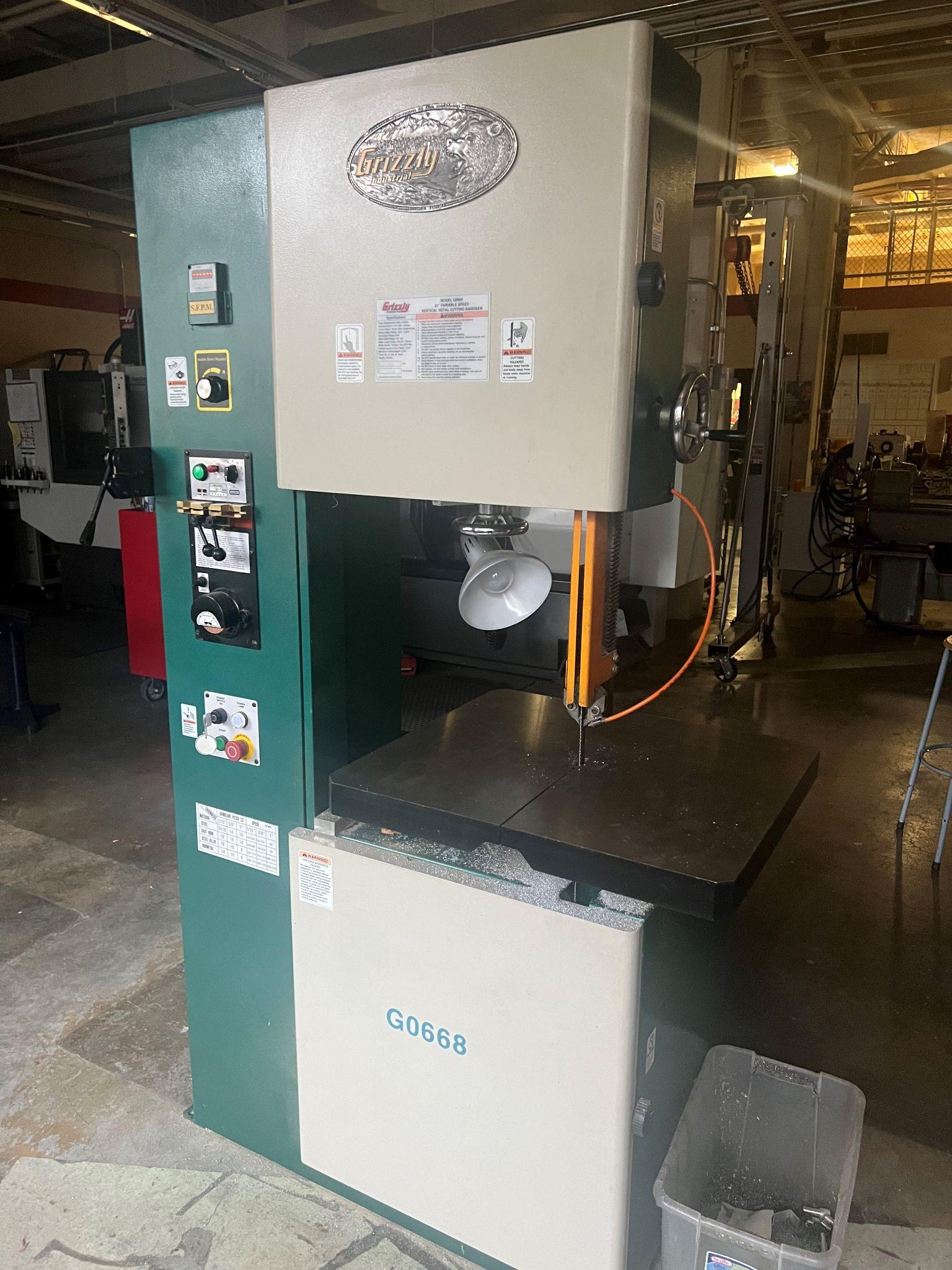
- Figure 6.10: Vertical bandsaw by T Bacon, courtesy of Bates Technical College, for WA Open ProfTech, © SBCTC, CC BY 4.0
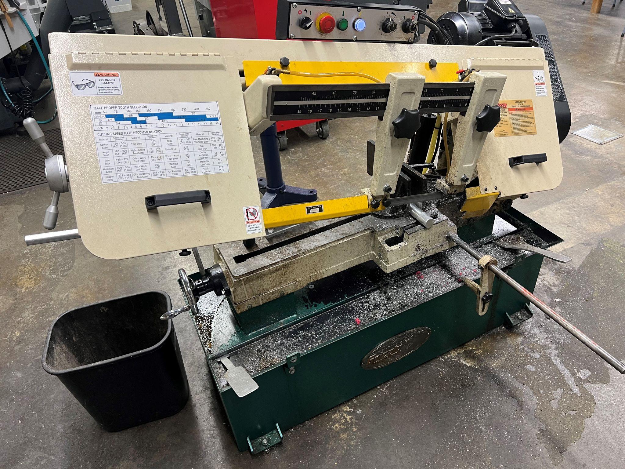
- Figure 6.11: Horizontal bandsaw by T Bacon, courtesy of Bates Technical College, for WA Open ProfTech, © SBCTC, CC BY 4.0
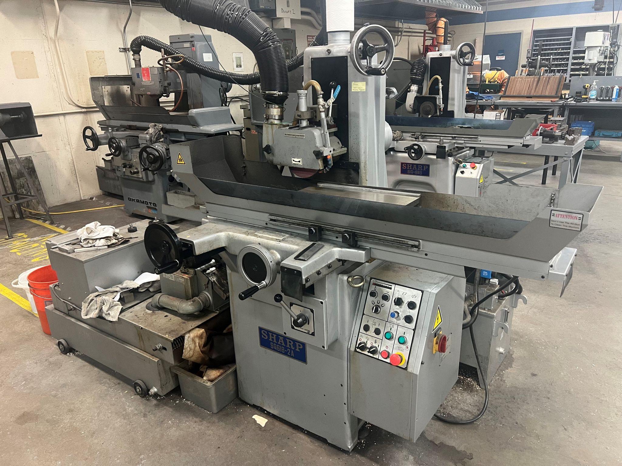
- Figure 6.12: Horizontal surface Grinder by T Bacon, courtesy of Bates Technical College, for WA Open ProfTech, © SBCTC, CC BY 4.0
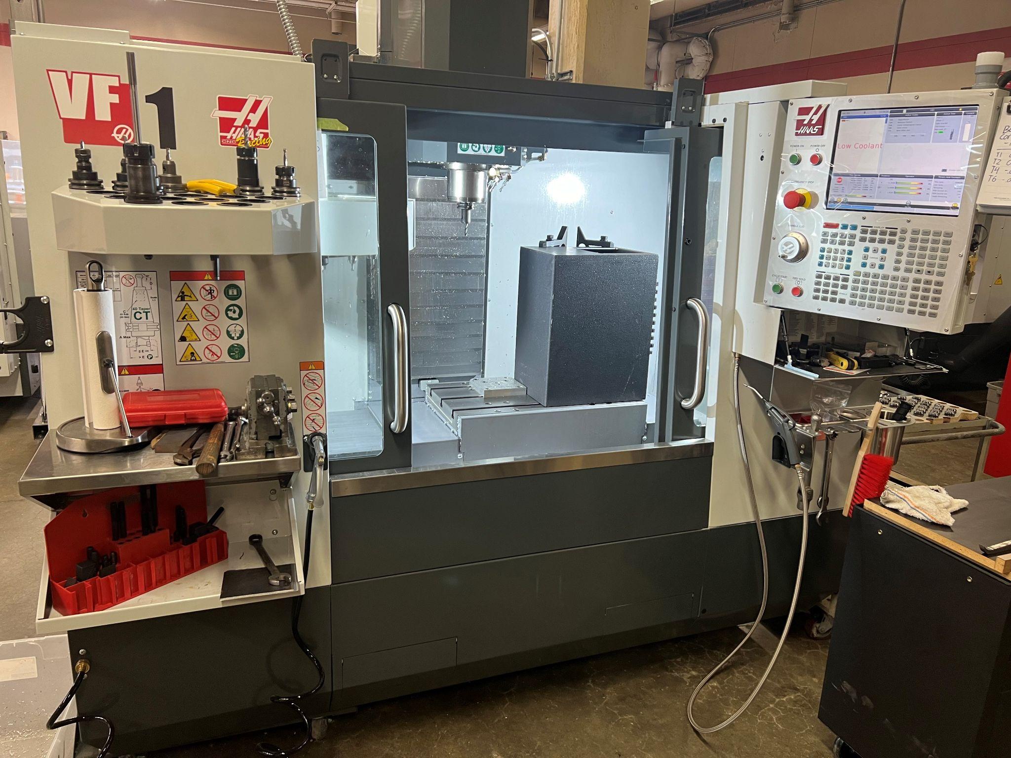
- Figure 6.13: Vertical CNC milling machine by T Bacon, courtesy of Bates Technical College, for WA Open ProfTech, © SBCTC, CC BY 4.0
