8.5 Work Setup
Micky R. Jennings
The work setup is the way the operator holds the material in order to perform the cutting operations. One of the main aspects of setting up a job is establishing the datums that are referenced on a print (see Chapter 3). A datum is a surface, line, or point that the dimensions of the print use as a reference. The dimensions of the print need to be represented in the work machinists perform. These datums may be intentionally called out as in a GD&T style print, or just implied by having one or more dimensions linked to a side of the part, as in a traditional print. Sometimes machinists will establish datums without even realizing it. When the operator puts a part in a vise, they establish one datum where the part sits at the bottom of the vise. If the table is square to the machine, the bottom of the vise is parallel to the top, so the bottom of the part is also parallel to the top. Any hole type features that are put in the top surface will be perpendicular to that surface. A good example of establishing datums for drill press work is the layout process. When making intersecting layout lines on a part, the machinist must make the line parallel to the edge or feature that is referenced in the print. That edge or feature is an implied datum.
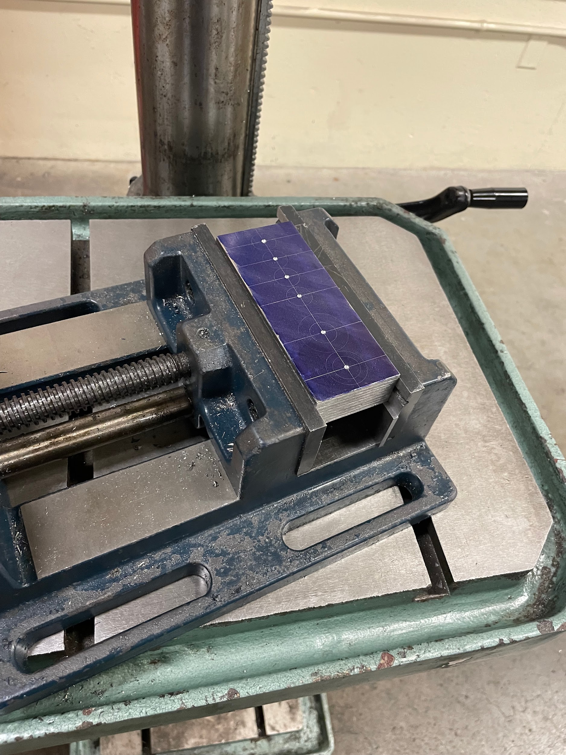
After the layout process is complete, the operator must set the job up on the drill press. Depending on the size and shape of the work, this process will vary. The illustration below shows a machinist putting a basic square-shaped part into a vise and establishing the third datum in the process. The part should be put in the vise so that it is secure and that the top of the part sits slightly above the top of the jaws. This is done by resting the part on parallels. When a part is installed on parallels, the machinist must make sure both the vise and the parallels are clean and free of burrs. Once the part is in the vise and the vise is tightened, parallels need to be seated. This is accomplished by wiggling the parallels side to side underneath the clamped part while tapping the top of the part with a dead blow hammer until both of the parallels become tight. If the part isn’t square, it is possible for the side of the part to conform to the solid jaw of the vise rather than the bottom of the part conforming to the parallels, making only one parallel become tight. If that happens, and it is critical that the bottom surface is the primary datum, loosen the part in the vise a little bit until the part conforms to the parallels.
If a part can be allowed to float on the table to machine all of the hole features, then the machinist could go ahead and start the process of center/spot drilling and so on. However, if the hole feature that is to be machined is going to create a great deal of torque, the machinist will need to put some sort of rotational stop in place to keep the vise from twisting uncontrollably.
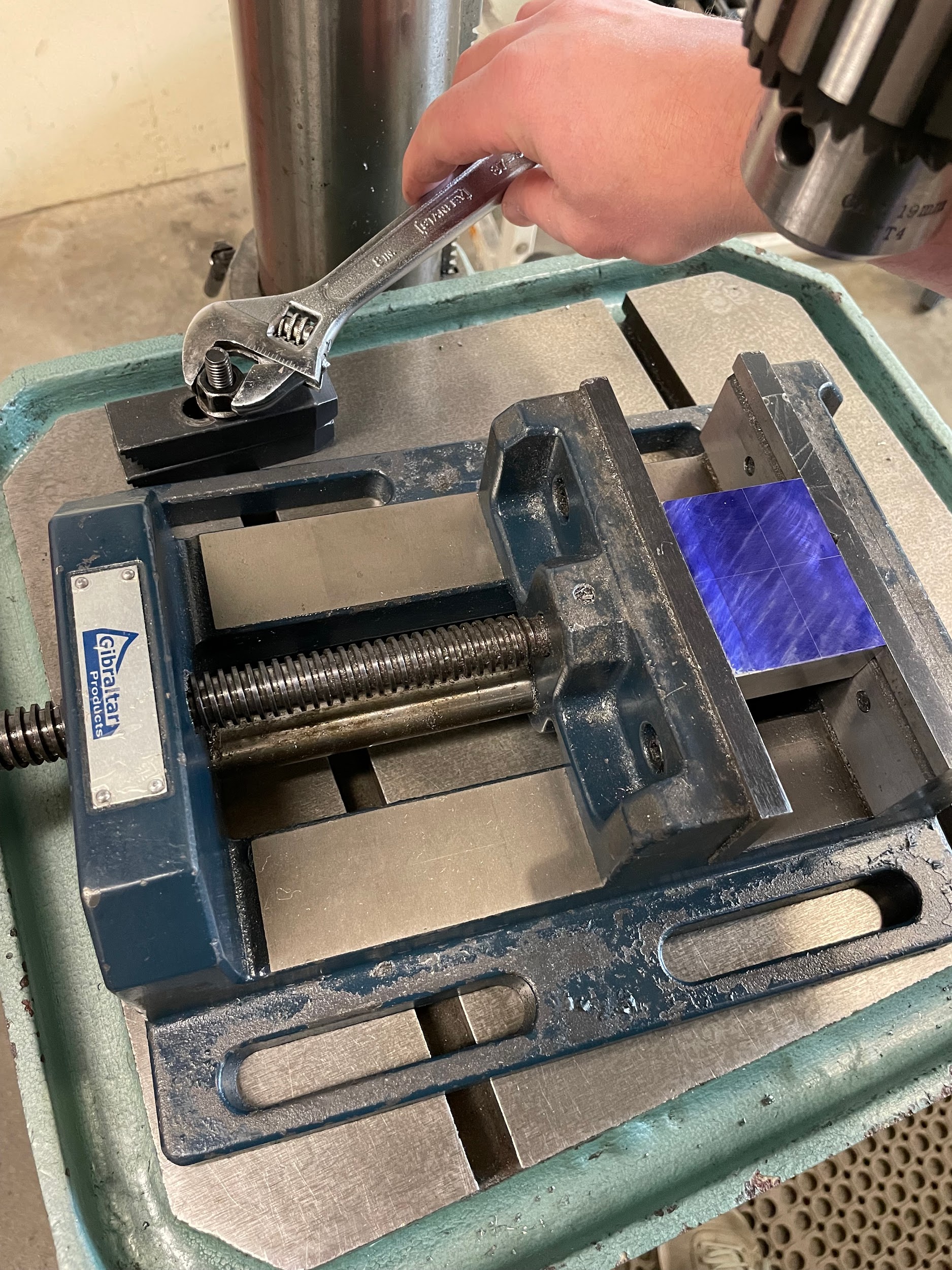
On occasion, just retaining the rotational force of the part isn’t enough. Sometimes the operator needs to clamp the vise to the table to limit the overall movement so that the rigidity of the setup can be increased, or multiple operations can be kept inline. Examples of these instances are when using drills over ½’ in diameter, creating a tapped hole, or creating a countersunk hole to name a few. The precaution to be observed with clamping the vise to the table is that the operator can override the established layout lines or center punch marks. Once the vise is tight, the center drill will drill directly beneath the spindle regardless of where the lines and marks are. In order to help line up the work and layout directly under the spindle, a center finder can be used.
Step by step process for work setup:
- Gather all of the tools that will be used in the process of machining the hole feature, including the center finder.
- Select the longest and shortest combination of tools and test them in the spindle/chuck making sure each will reach the required depth and can be inserted and removed without moving the table.
- Install the center finder with the pointer attachment into the drill chuck.
- Center the pointer as well as possible by hand.
- Set the spindle to approximately 1000 RPMs.
- Turn on the spindle.
- Press a block of wood or plastic into the side of the wiggling pointer until it begins to spin still and looks as if it isn’t moving.
- Turn off the spindle.
- Bring the quill of the drill press down until the pointer tip is within 1/64″ of the top of the work.
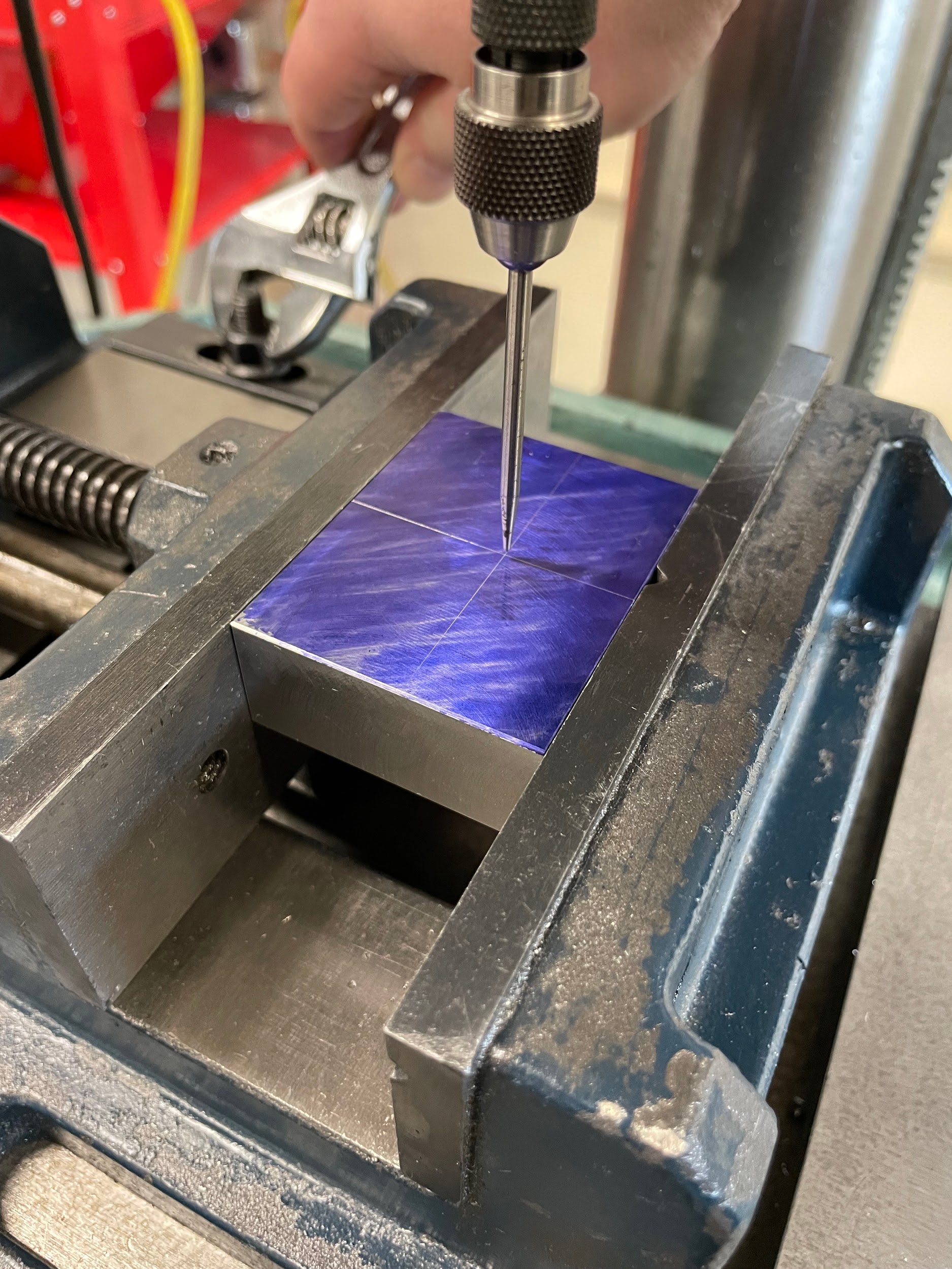
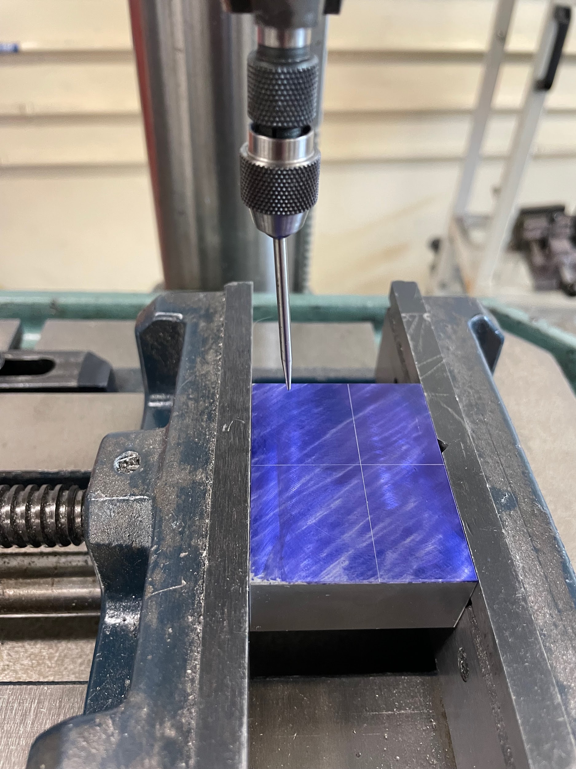
- Line up the layout lines with the static tip of the pointer.
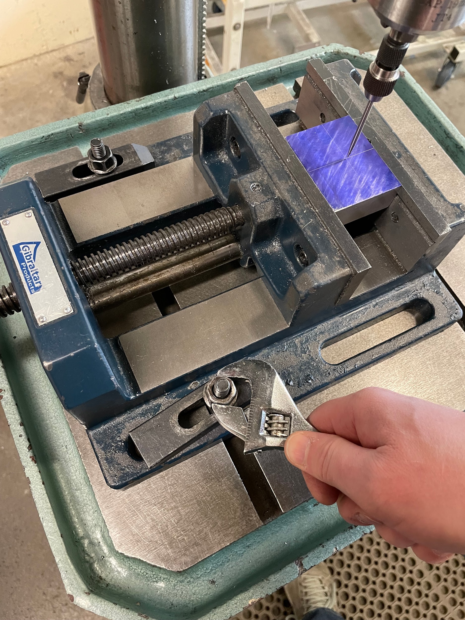
- Securely clamp the vise to the table.
- Critically recheck the lineup of the layout lines and the pointer. If it isn’t aligned, loosen the clamps and try again until it is.
- Start the spindle and double check that the pointer tip is still spinning true. If it has become bumped out of place, true it and set up the alignment again.
- If prick or center punches are being aligned, the pointer tip can gently be inserted into the mark while spinning. If the part is in alignment with the spindle, the pointer will continue to spin true. If the part is out of alignment, the pointer will start wiggling as it touches the side of the mark before it reaches the bottom. If this happens, attempt the alignment again until the pointer spins true while in the mark.
“Step 3: Install the center finder with the pointer attachment into the drill chuck.”
“Step 7: Press a block of wood or plastic into the side of the wiggling pointer until it begins to spin still and looks as if it isn’t moving.”

“Step 10: Line up the layout lines with the static tip of the pointer.”

“Step 10: Line up the layout lines with the static tip of the pointer.”

“Step 11: Securely clamp the vise to the table.”
Attributions
- Figure 8.34: Part mounted in drill press vise by Micky R. Jennings, courtesy of Wenatchee Valley College, for WA Open ProfTech, © SBCTC, CC BY 4.0
- Figure 8.35: Rotational stop by Micky R. Jennings, courtesy of Wenatchee Valley College, for WA Open ProfTech, © SBCTC, CC BY 4.0
- Figure 8.36: Aligning center finder pointer by Micky R. Jennings, courtesy of Wenatchee Valley College, for WA Open ProfTech, © SBCTC, CC BY 4.0
- Figure 8.37: Center finder by Micky R. Jennings, courtesy of Wenatchee Valley College, for WA Open ProfTech, © SBCTC, CC BY 4.0
- Video 8.4: Micky R. Jennings, courtesy of Wenatchee Valley College, for WA Open ProfTech, © SBCTC, CC BY 4.0
- Video 8.5: Micky R. Jennings, courtesy of Wenatchee Valley College, for WA Open ProfTech, © SBCTC, CC BY 4.0
- Figure 8.38: Aligning center finder pointer by Micky R. Jennings, courtesy of Wenatchee Valley College, for WA Open ProfTech, © SBCTC, CC BY 4.0
- Figure 8.39: Tightening vise by Micky R. Jennings, courtesy of Wenatchee Valley College, for WA Open ProfTech, © SBCTC, CC BY 4.0
