8.6 Tool Holding
Micky R. Jennings
Tool holding is an essential part of any piece of metal cutting equipment. There has to be a specific device or way of keeping the interchangeable cutting tools attached to the machine. Generally speaking, drill presses rely on self holding tapers and chucks to hold tools tight and concentric with the machine spindle. These holding methods are perfect for the plunging cuts the drill press is designed for.
Morse Taper
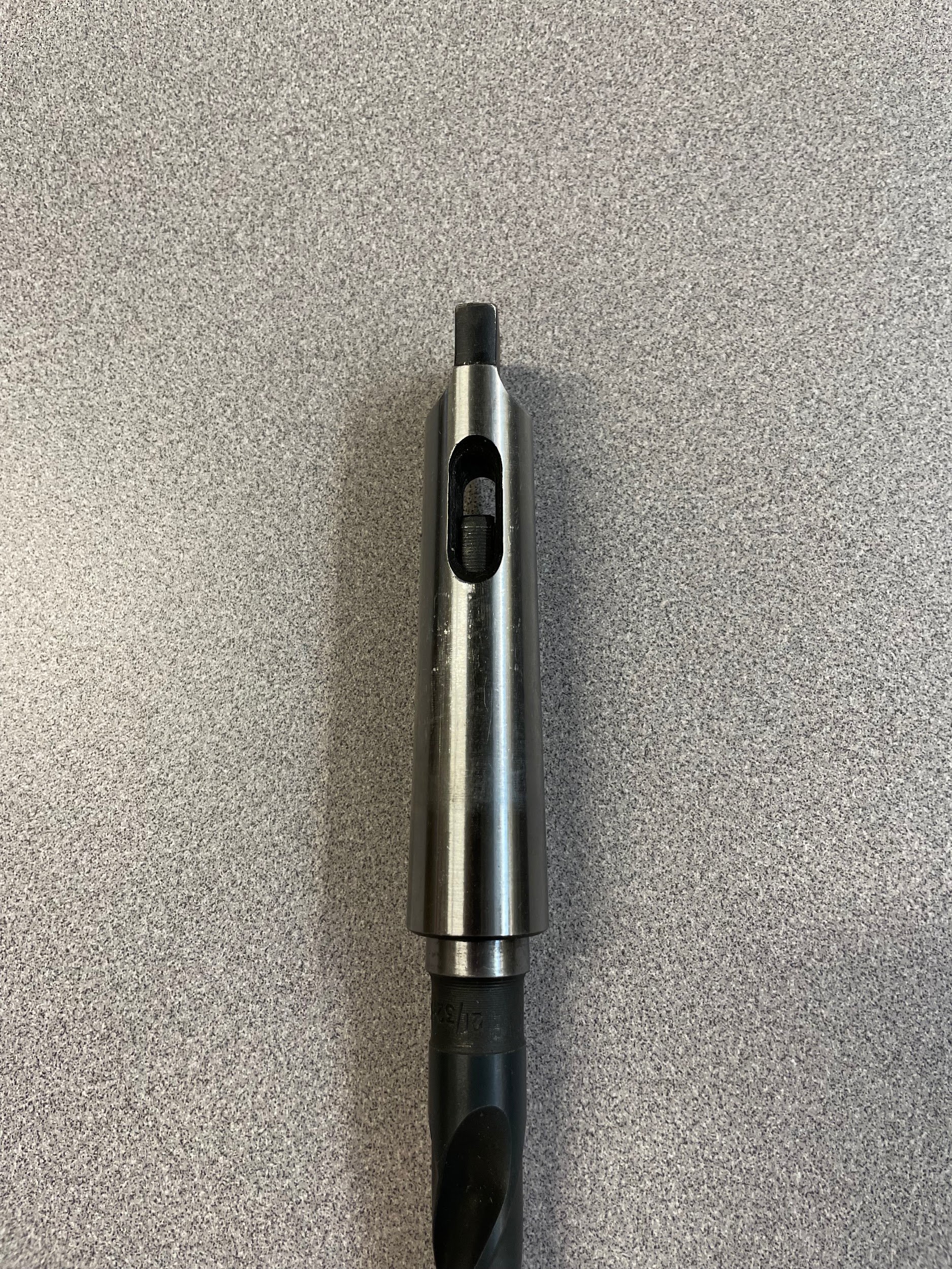
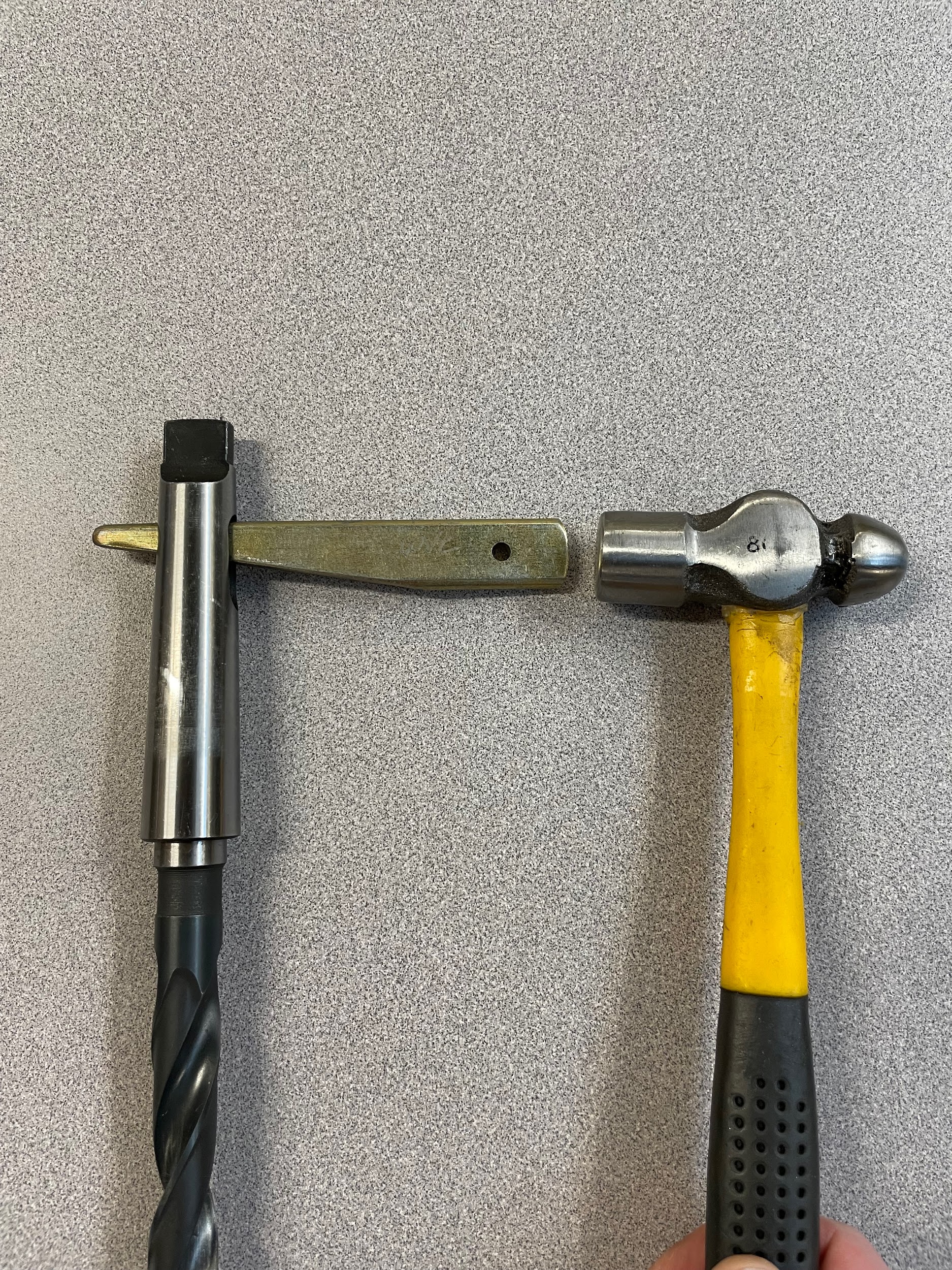
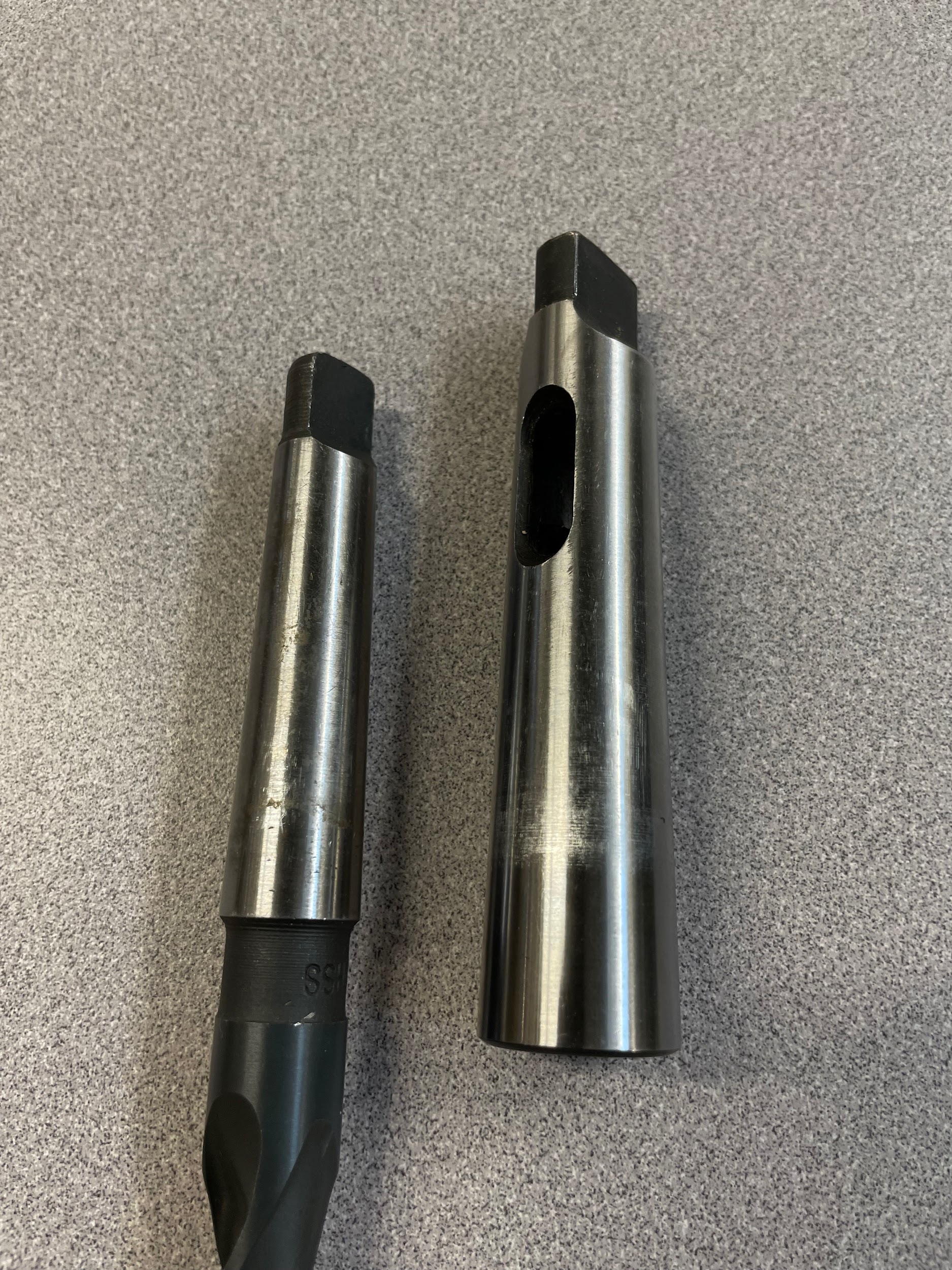
The Morse taper is one of the oldest tool holding devises in machining. In the 1860s, Stephen A. Morse developed a quick and reliable method for holding twist drills. This method is now known worldwide as the Morse taper (Hernigou et al., 2013; Modern Machinery, 1899). Morse tapers are considered a self-holding taper and are suitable for a lot of manual machinery in a shop. The Morse taper holds tools in alignment by a tight wedging action of both parts of the mating tapers. Often, the Morse taper will have a flattened portion at the end, known as a tang. This tang is for alignment and removal of the tool. Morse tapers are a suitable tool holding method for drilling style operations that have forces pushing up into the spindle as well as a twisting force. They are not a good choice for sideways force, as this could loosen the taper and dislodge the tool.
Drill Chuck
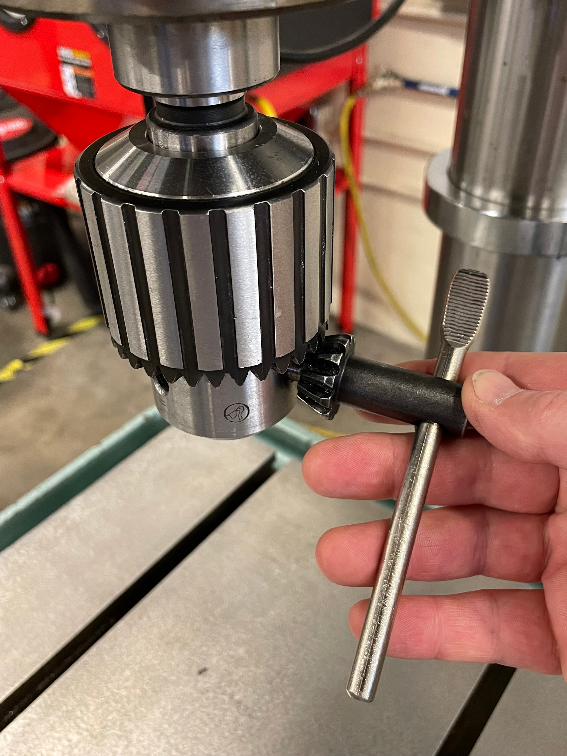
The first keyed drill chuck was invented by Arthur Irving Jacobs in the 1900s as a better way to hold twist drills (Apex Tool Group, n.d.). A basic drill chuck is a complex device that uses multiple jaws to grip the straight shanks of drilling cutting tools. As the outer collar of the chuck is rotated, either by hand or by chuck key, the jaws synchronously close on the cutting tool, gripping it with a high level of concentricity. The interior components of a drill chuck have many ground precision surfaces in order for this to work correctly. Low quality or worn chucks may have tool runout that is unacceptable for some operations.
Jacobs Taper
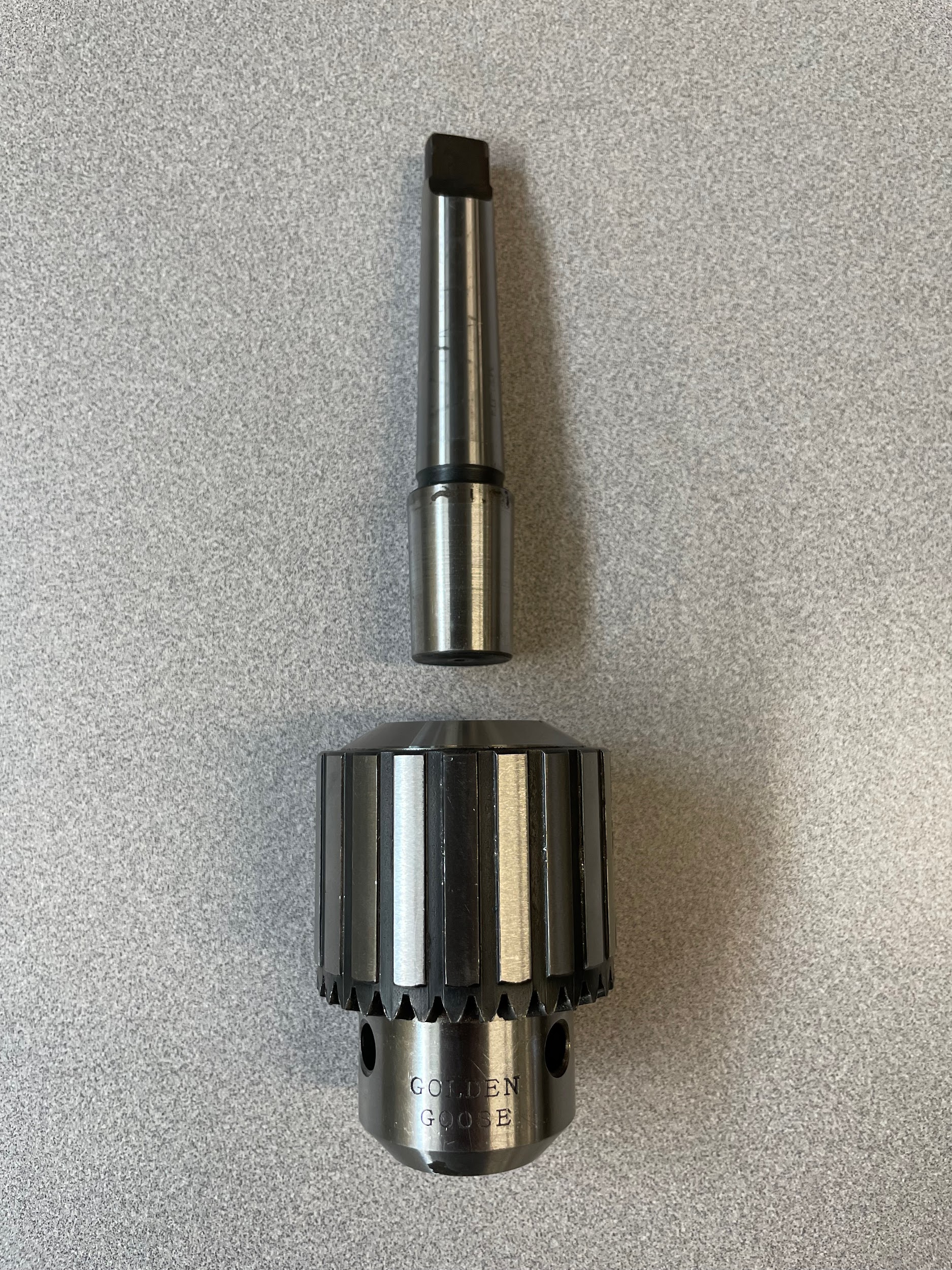
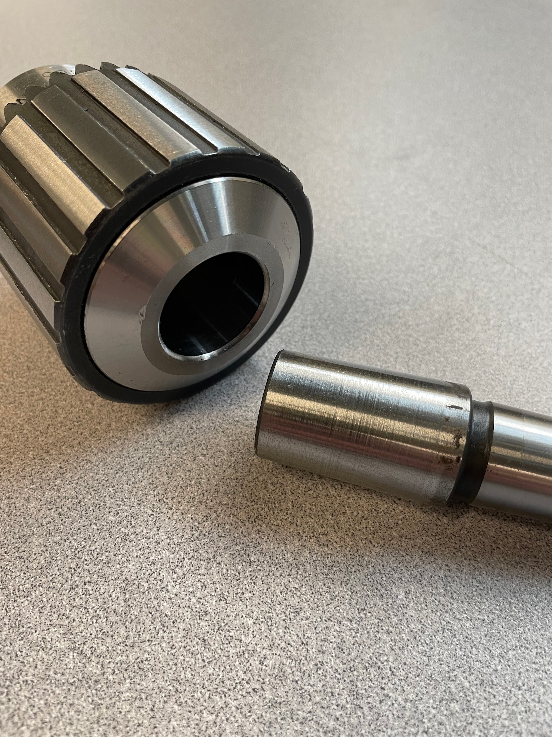
A Jacobs taper is another self-holding taper that is used as an attachment method for drill chucks. It was invented in the 1900s by the Jacobs Chuck company as a coupling method for attaching drill chucks onto machine tools (Apex Tool Group, n.d.). The chuck itself has a Jacobs taper, and the machinery generally has a Morse taper. An arbor, having a Jacobs taper on one end and a Morse taper on the other, connects the chuck to the machine.
Attributions
- Figure 8.40: A Morse taper socket on a taper shank drill by Micky R. Jennings, courtesy of Wenatchee Valley College, for WA Open ProfTech, © SBCTC, CC BY 4.0
- Figure 8.41: Morse taper socket removal by Micky R. Jennings, courtesy of Wenatchee Valley College, for WA Open ProfTech, © SBCTC, CC BY 4.0
- Figure 8.42: Morse taper shank drill and socket separated by Micky R. Jennings, courtesy of Wenatchee Valley College, for WA Open ProfTech, © SBCTC, CC BY 4.0
- Figure 8.43: Keyed drill chuck with key engaged by Micky R. Jennings, courtesy of Wenatchee Valley College, for WA Open ProfTech, © SBCTC, CC BY 4.0
- Figure 8.44: Chuck and arbor by Micky R. Jennings, courtesy of Wenatchee Valley College, for WA Open ProfTech, © SBCTC, CC BY 4.0
- Figure 8.45: Chuck and arbor 2 by Micky R. Jennings, courtesy of Wenatchee Valley College, for WA Open ProfTech, © SBCTC, CC BY 4.0
a self-holding taper used in a variety of applications including: reamers, drill bits, mill holders, collets, and lathe centers.
A device used to easily hold hole making tools.
a self-holding taper used for light-duty applications to secure a drill chuck to an arbor.
