9.10 Face Milling
Micky R. Jennings
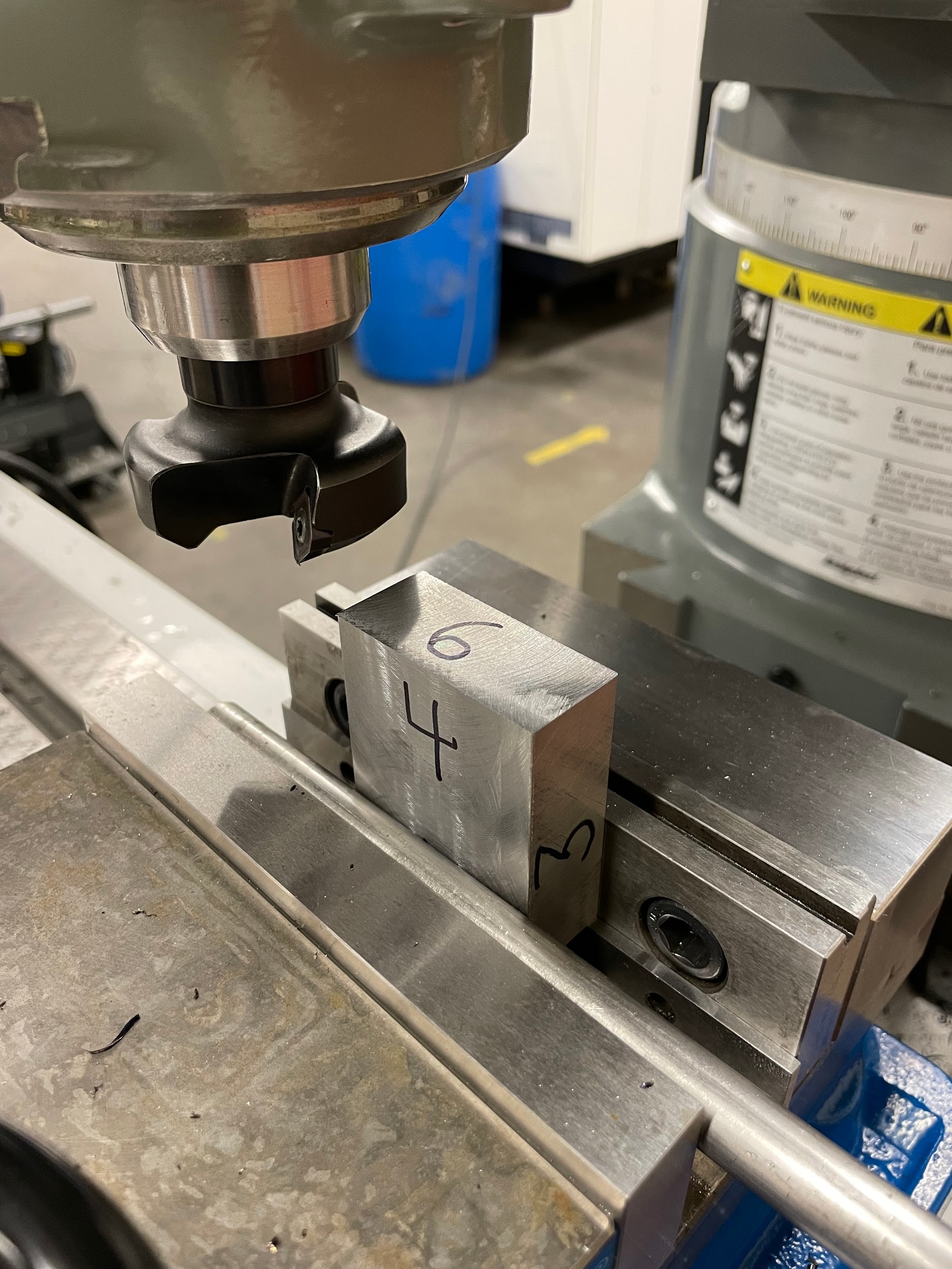
Face milling, or facing, is the process of establishing an accurate surface of the part. This surface will be used as a reference for other feature depths. For that reason, it is often the first operation performed on raw material on a milling machine.
Step by step process for face milling:
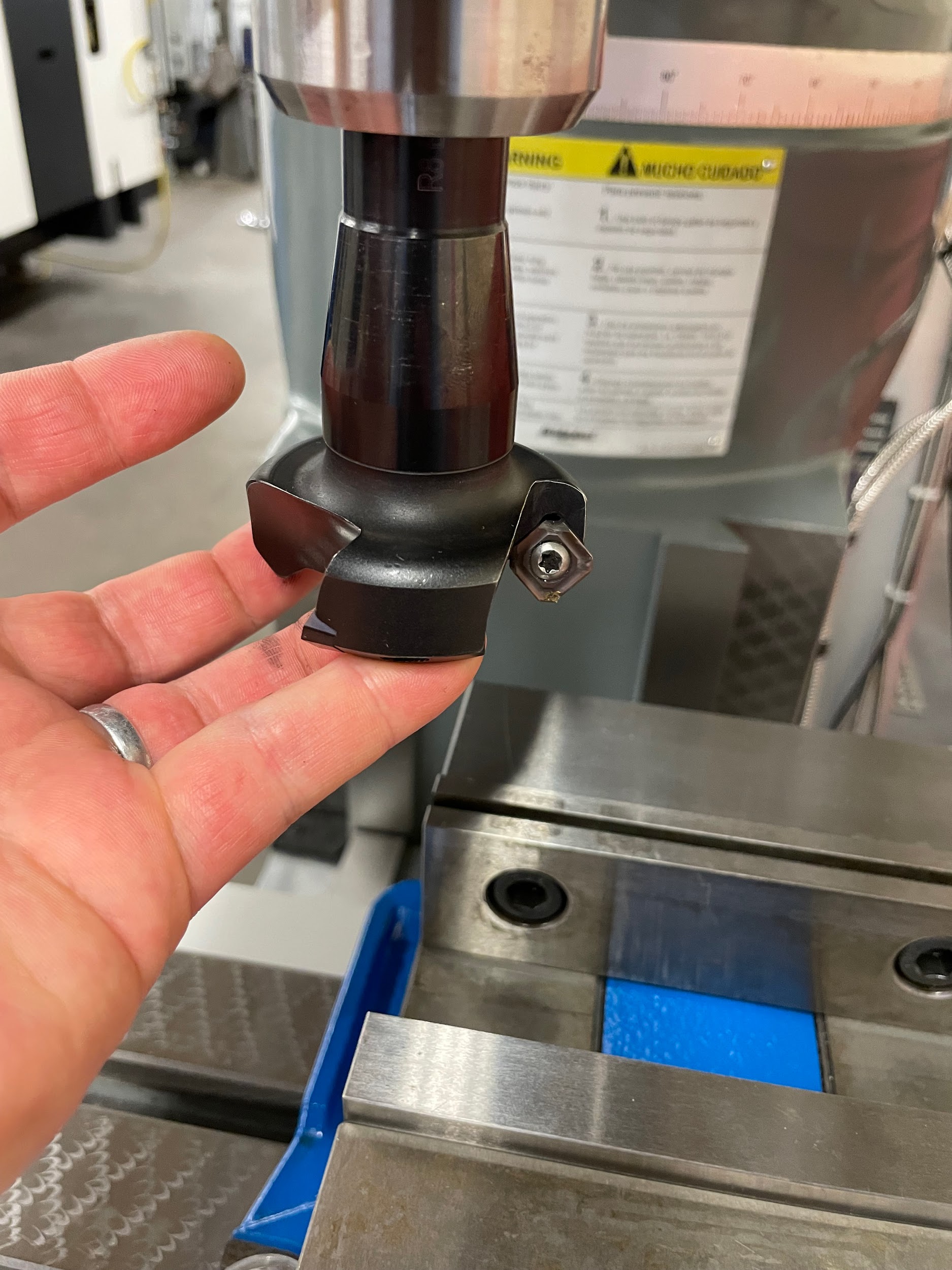
- Load a face mill into the milling machine.
- Load a piece of material into a mill vise and onto a pair of parallels and tighten the handle.
- Gently tap the part downward with a dead blow hammer to seat the part securely on at least one of the parallels.
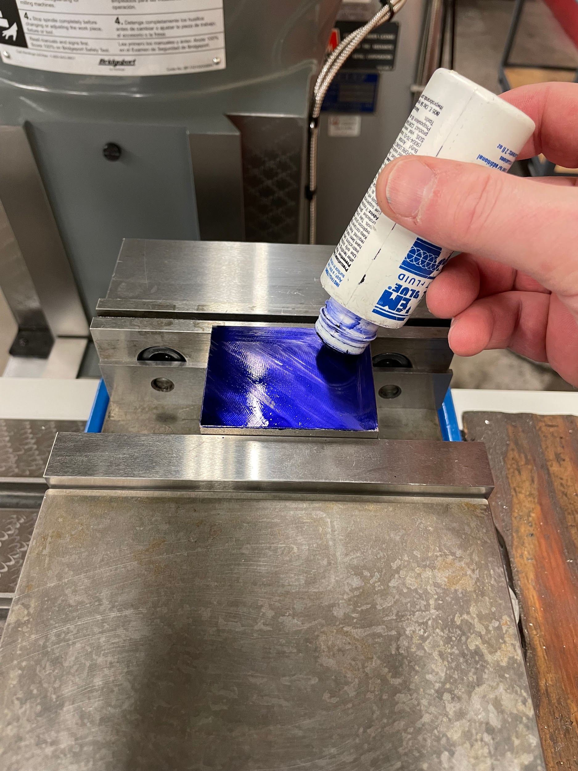
- Apply some layout dye to the top of the part.
- Calculate a spindle speed based on the SFPM and the diameter of the tool.
- Calculate a feed rate based on the finish requirement of the part. CPT selection for a face mill is different than that of an end mill because the face mill can often handle larger CPT than will look good for a surface finish. As small as .003 or as large as .030 or more could be used, depending on finished part surface requirements.
- Pull the quill handle down about 1/2″ and lock the quill in place. The quill should always be locked for sideways milling operations, regardless of where the position is.
- Move the table, saddle and knee to where the tool is just above the part by about 1/2″ and centered by the saddle movement. Lock the saddle.
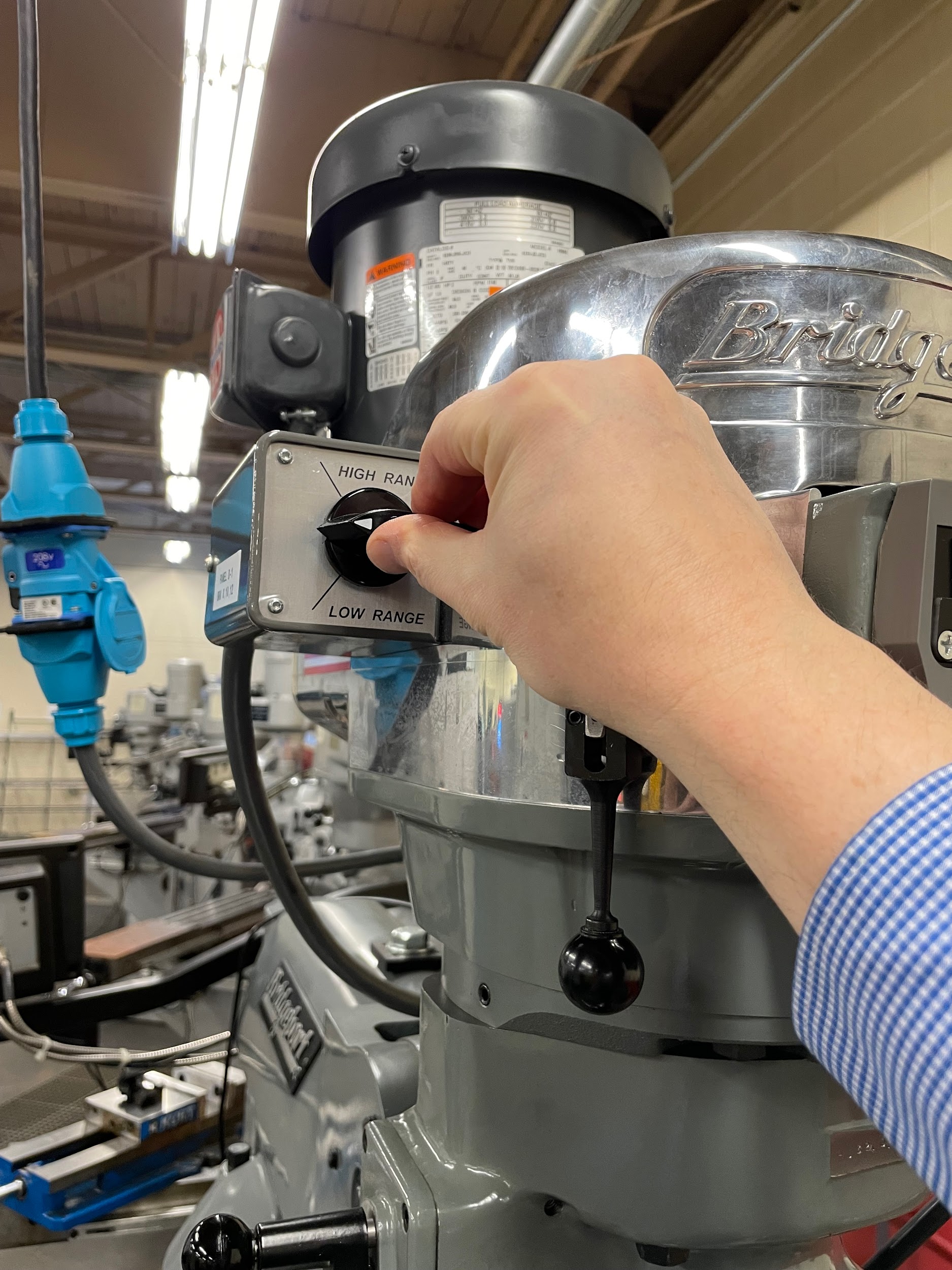
- Put the machine into low or high gear range.
- Turn on the spindle
- Adjust the speed.
- Slowly move the knee up until the inserts of the face mill just remove the layout dye.
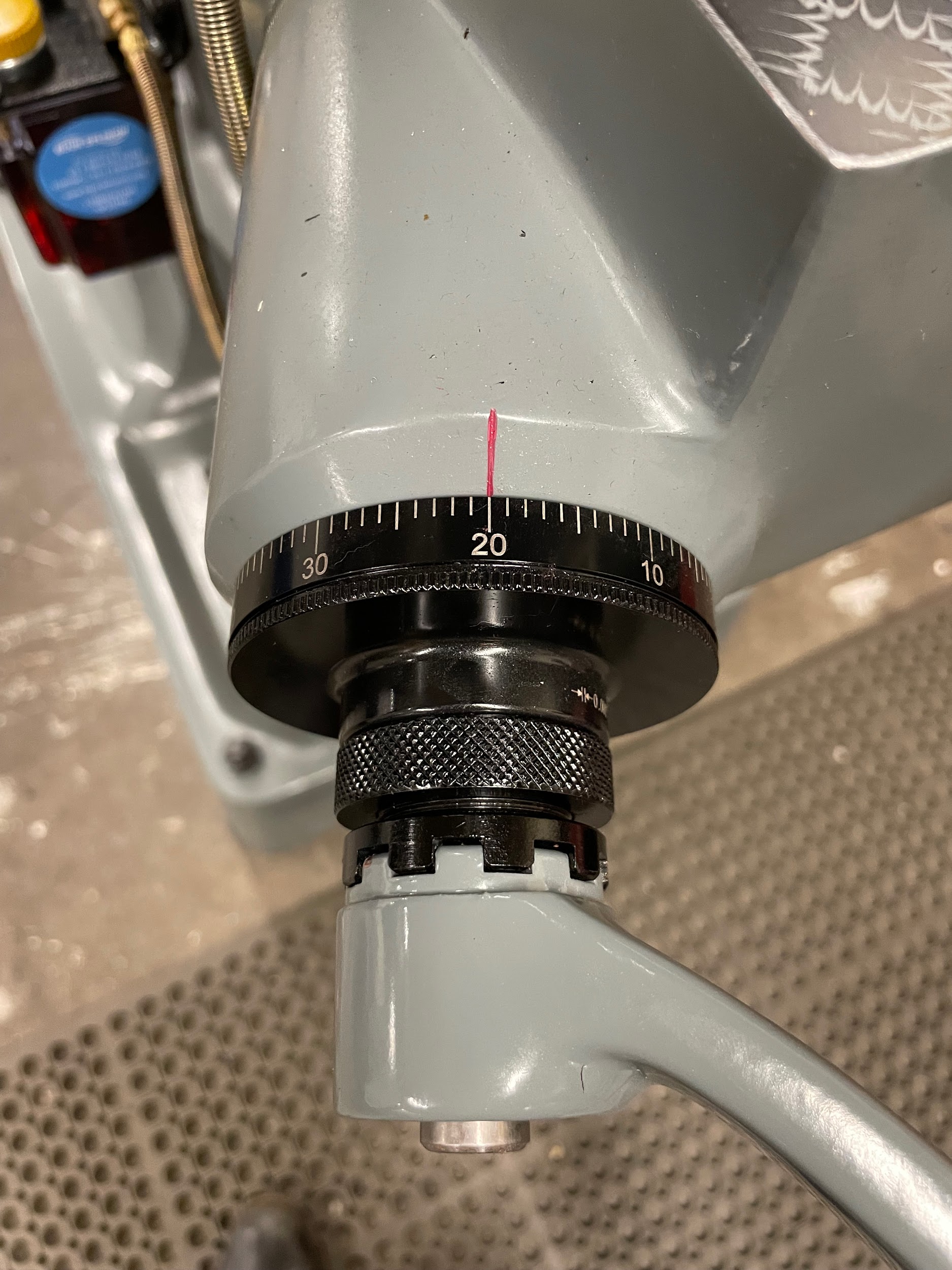
- Zero the knee graduated collar.
- With the table movement, move the part out from under the face mill.
- Using the knee, set a depth of cut.
- Using the table hand wheel or the powered unit, move the part underneath and past the work at the calculated feed rate.
- Turn off the spindle.
- Inspect for fully milled surface and/or thickness of part and repeat if necessary.
- Remove tool from spindle by holding brake with left hand and loosening draw bar with right hand.
- Once loose, place the left hand under the tool and further unscrew the draw bar one full turn by hand. Only one full turn!
- With a rag in the left hand, cradle the tool and tap on the top of the draw bar to release the machine taper. If the draw bar is fully unscrewed when the operator attempts to tap the tool out of the spindle, the last thread of the tool and draw bar will become damaged and broken over time.
- Clean the face mill and return it to the storage area.
Step 1: Load a face mill into the milling machine.
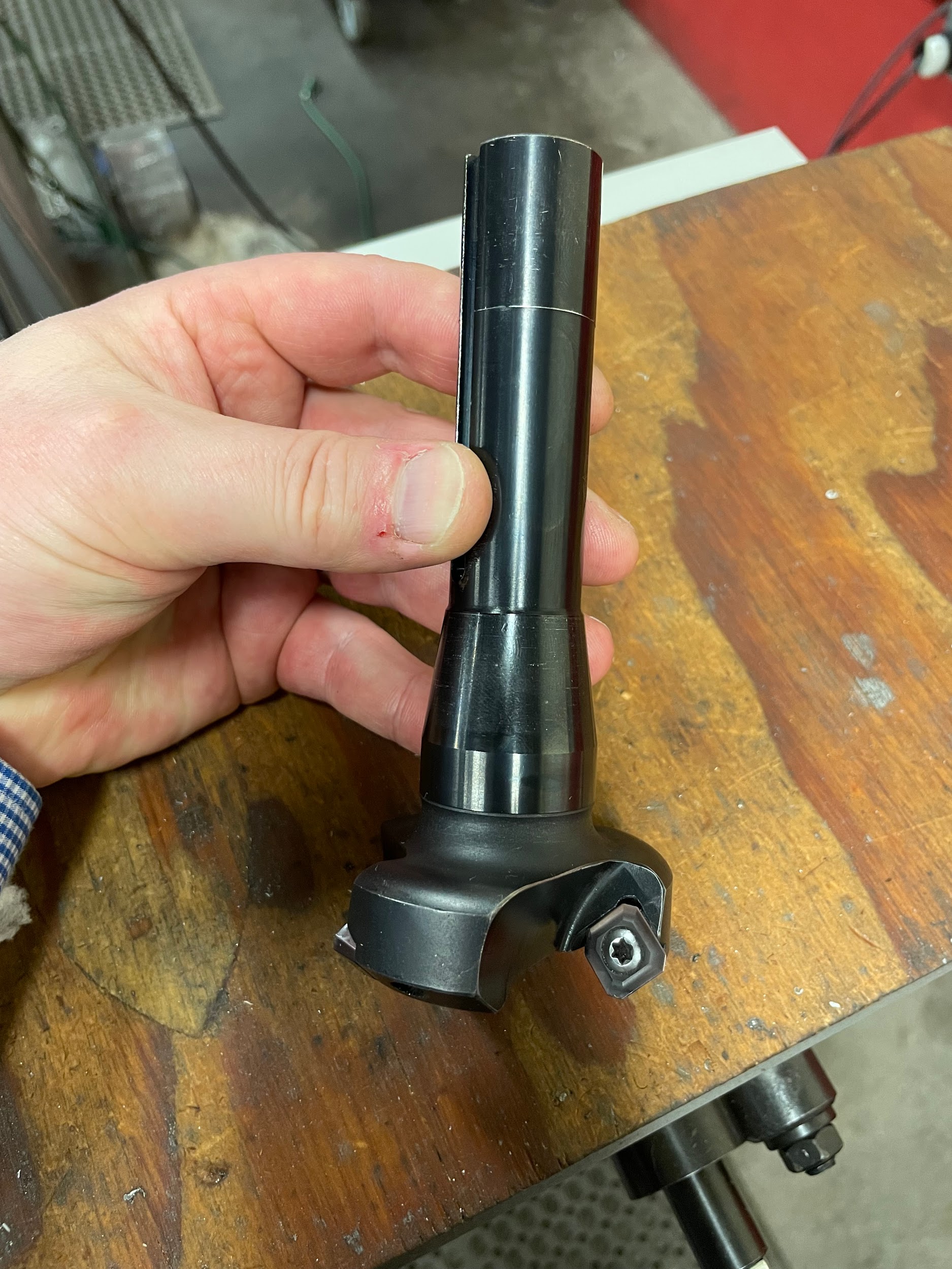
Step 1: Load a face mill into the milling machine.
Step 4: Apply some layout dye to the top of the part.
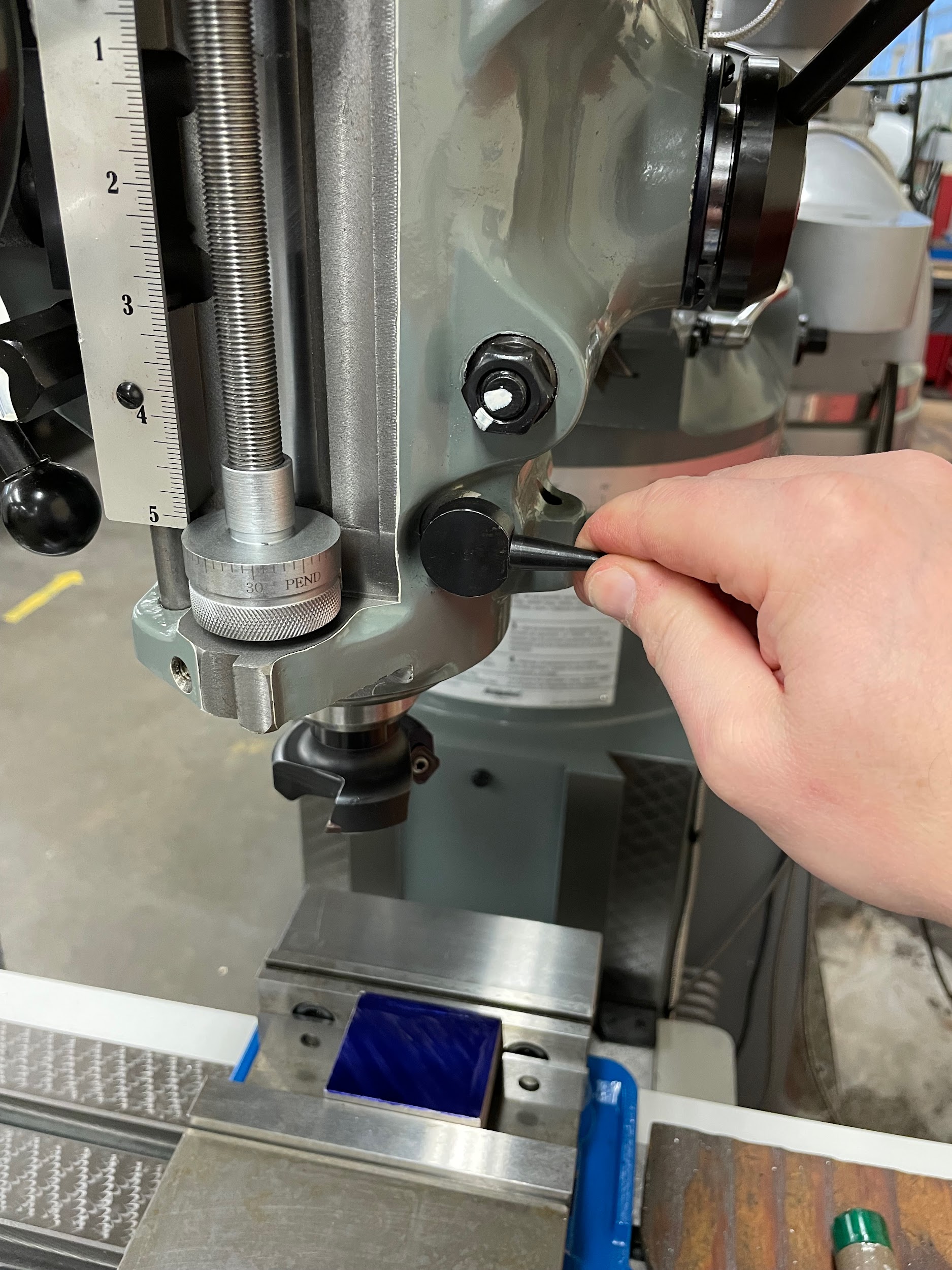
Step 7: Pull the quill handle down about 1/2″ and lock the quill in place. The quill should always be locked for sideways milling operations, regardless of where the position is.
Step 8: Move the table, saddle and knee to where the tool is just above the part by about 1/2″ and centered by the saddle movement. Lock the saddle.
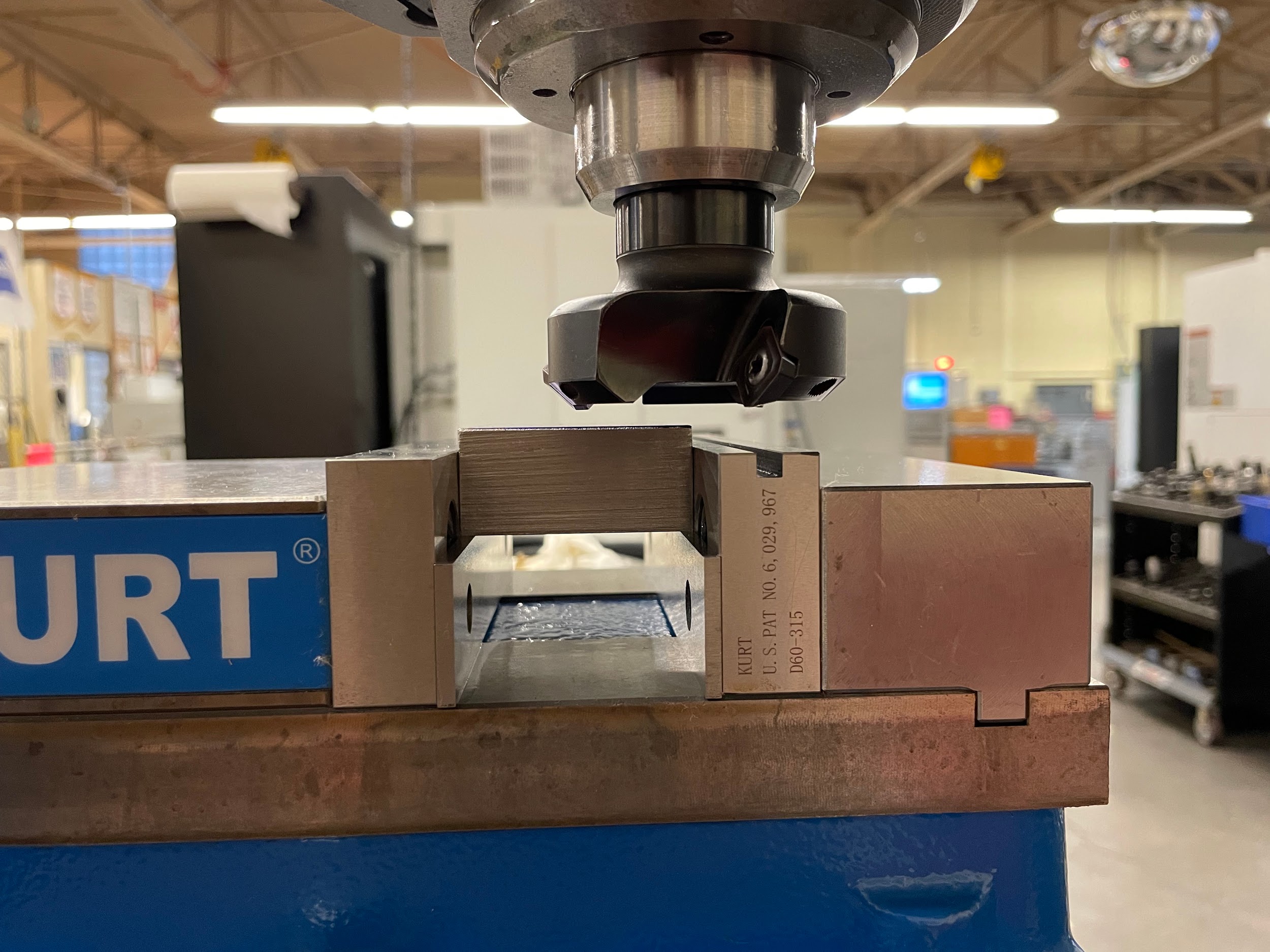
Step 8: Move the table, saddle, and knee to where the tool is just above the part by about 1/2″ and centered by the saddle movement. Lock the saddle.
Step 10: Turn on the spindle
Step 11: Adjust the speed.
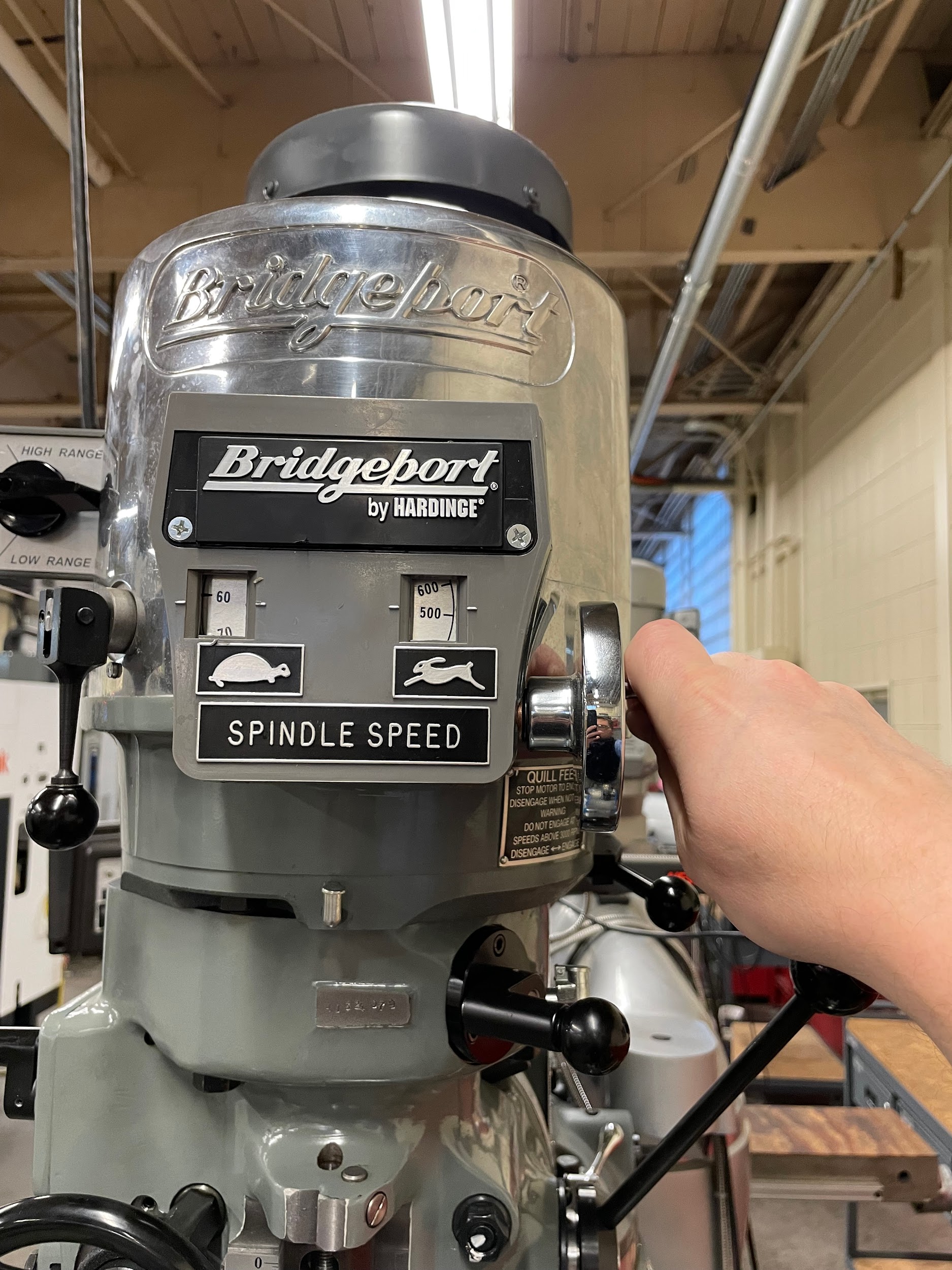
Step 11: Adjust the speed.

Step 12: Slowly move the knee up until the inserts of the face mill just remove the layout dye.

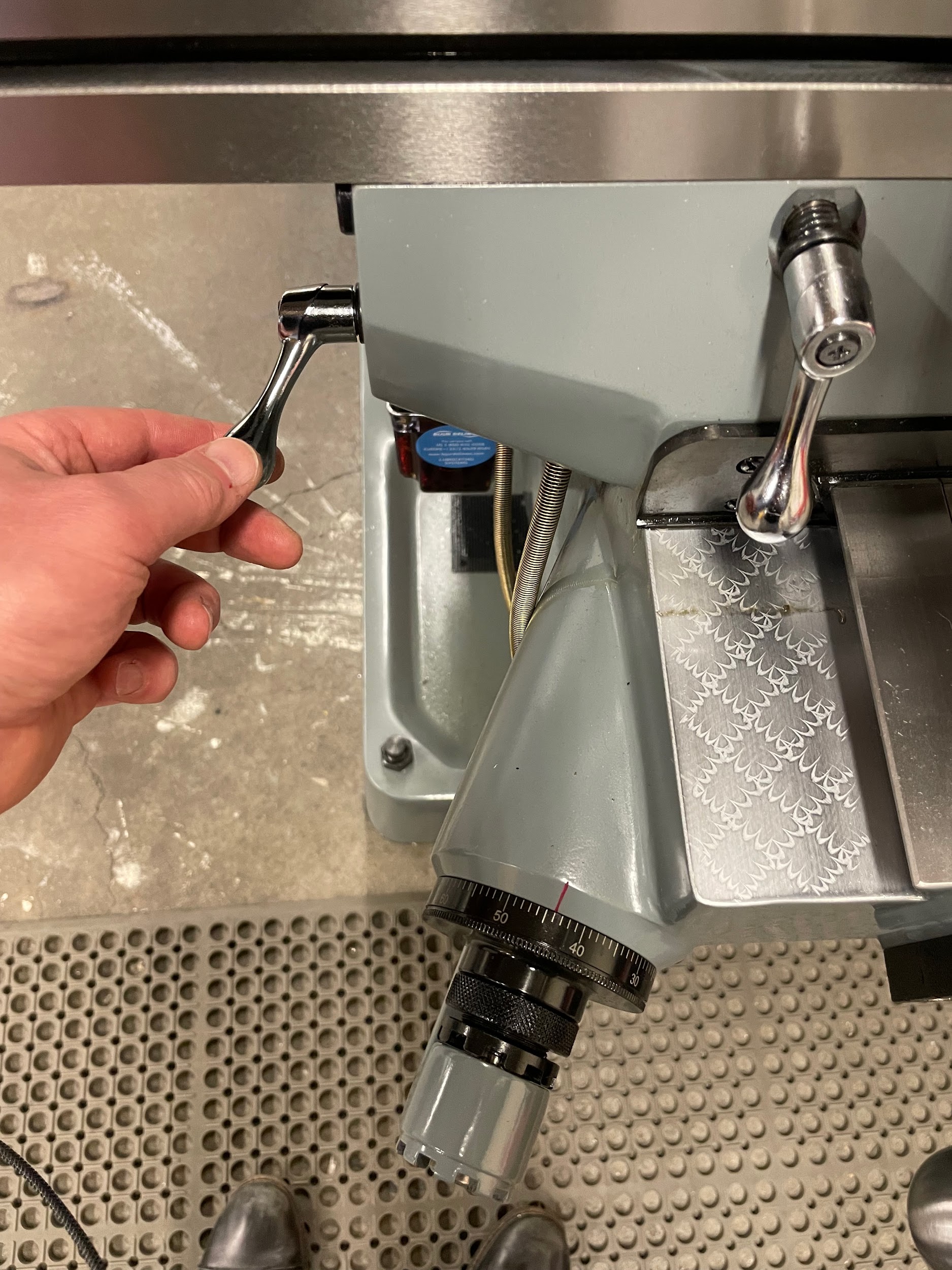
Step 13: Zero the knee graduated collar.

Step 15: Using the knee, set a depth of cut.
Step 16: Using the table hand wheel or the powered unit, move the part underneath and past the work at the calculated feed rate.

Step 16: Using the table hand wheel or the powered unit, move the part underneath and past the work at the calculated feed rate.

Attributions
- Figure 9.138: Facing a block by Micky R. Jennings, courtesy of Wenatchee Valley College, for WA Open ProfTech, © SBCTC, CC BY 4.0
- Figure 9.139: Face mill by Micky R. Jennings, courtesy of Wenatchee Valley College, for WA Open ProfTech, © SBCTC, CC BY 4.0
- Figure 9.140: Loading a face mill by Micky R. Jennings, courtesy of Wenatchee Valley College, for WA Open ProfTech, © SBCTC, CC BY 4.0
- Figure 9.141: Applying layout dye by Micky R. Jennings, courtesy of Wenatchee Valley College, for WA Open ProfTech, © SBCTC, CC BY 4.0
- Figure 9.142: Locking the quill by Micky R. Jennings, courtesy of Wenatchee Valley College, for WA Open ProfTech, © SBCTC, CC BY 4.0
- Figure 9.143: Position the face mill by Micky R. Jennings, courtesy of Wenatchee Valley College, for WA Open ProfTech, © SBCTC, CC BY 4.0
- Figure 9.144: Locking the saddle by Micky R. Jennings, courtesy of Wenatchee Valley College, for WA Open ProfTech, © SBCTC, CC BY 4.0
- Figure 9.145: Turning the spindle on by Micky R. Jennings, courtesy of Wenatchee Valley College, for WA Open ProfTech, © SBCTC, CC BY 4.0
- Figure 9.146: Adjusting the spindle speed by Micky R. Jennings, courtesy of Wenatchee Valley College, for WA Open ProfTech, © SBCTC, CC BY 4.0
- Video 9.23: Micky R. Jennings, courtesy of Wenatchee Valley College, for WA Open ProfTech, © SBCTC, CC BY 4.0
- Video 9.24: Micky R. Jennings, courtesy of Wenatchee Valley College, for WA Open ProfTech, © SBCTC, CC BY 4.0
- Video 9.25: Micky R. Jennings, courtesy of Wenatchee Valley College, for WA Open ProfTech, © SBCTC, CC BY 4.0
- Figure 9.147: Depth of cut by Micky R. Jennings, courtesy of Wenatchee Valley College, for WA Open ProfTech, © SBCTC, CC BY 4.0
- Video 9.26: Micky R. Jennings, courtesy of Wenatchee Valley College, for WA Open ProfTech, © SBCTC, CC BY 4.0
- Video 9.27: Micky R. Jennings, courtesy of Wenatchee Valley College, for WA Open ProfTech, © SBCTC, CC BY 4.0
The process of using a face mill to create a flat top surface on a milling machine.
