9.11 Block Squaring
Micky R. Jennings
Block squaring is the process of performing face milling operations on each side of a block in a specific manner that transfers the precision of the mill vise into angular accuracy on the part. Each of the six sides of a rectangular block will be machined, creating the outer envelope of the overall size of the finished part.
Step by step process for block squaring:
- Side one
- Load a face mill into the spindle.
- Load a rectangular block of material into a milling vise with the largest side in preparation to be faced.
- Place the part on parallels.
- Take a 1/64″ to 1/32″ facing cut to clean the surface.
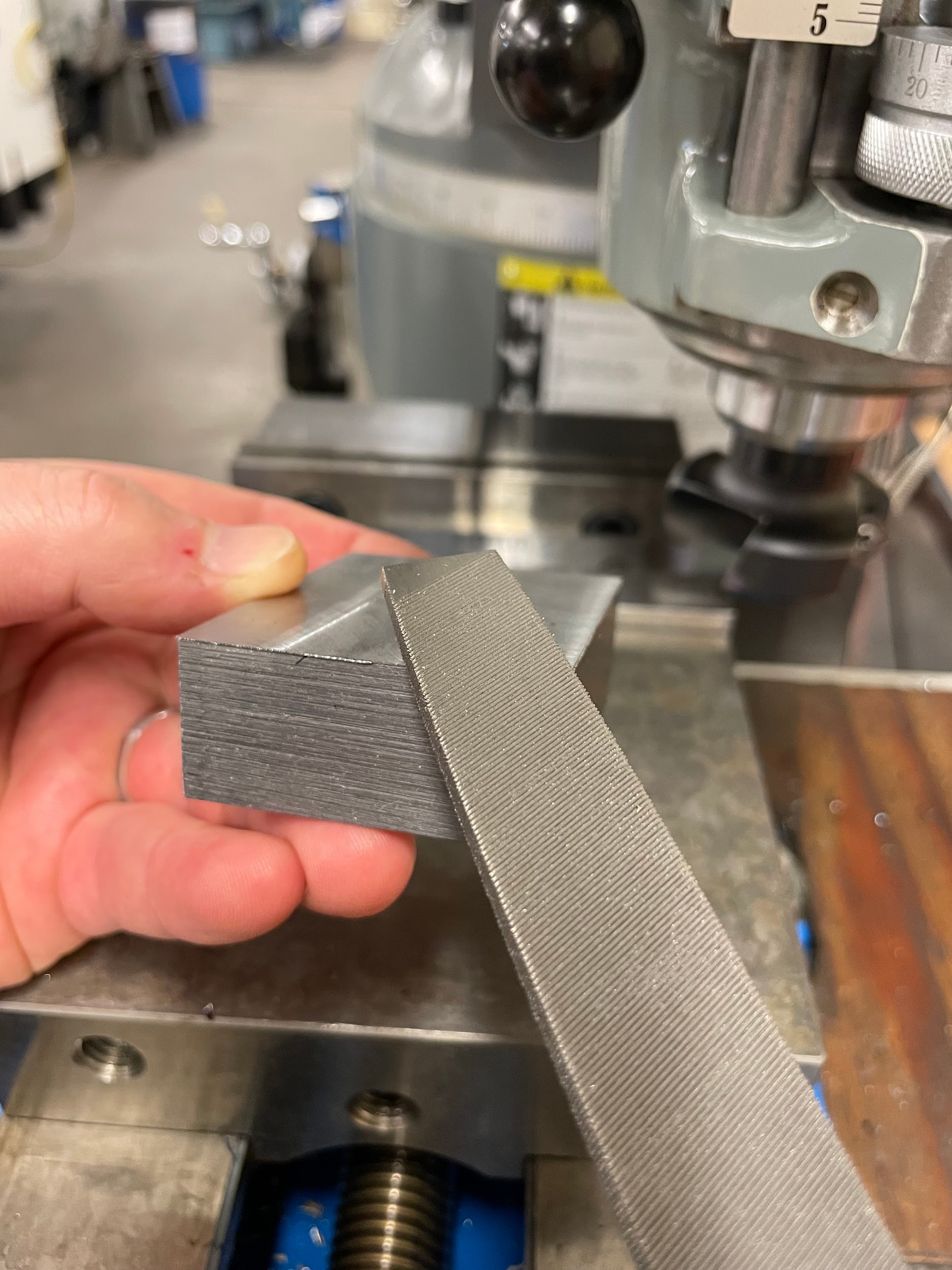
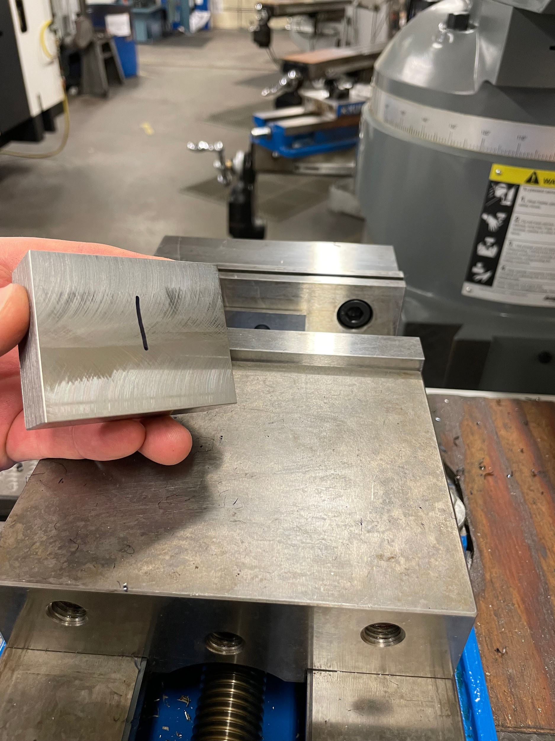
- Remove the part and deburr all edges.
- Side two
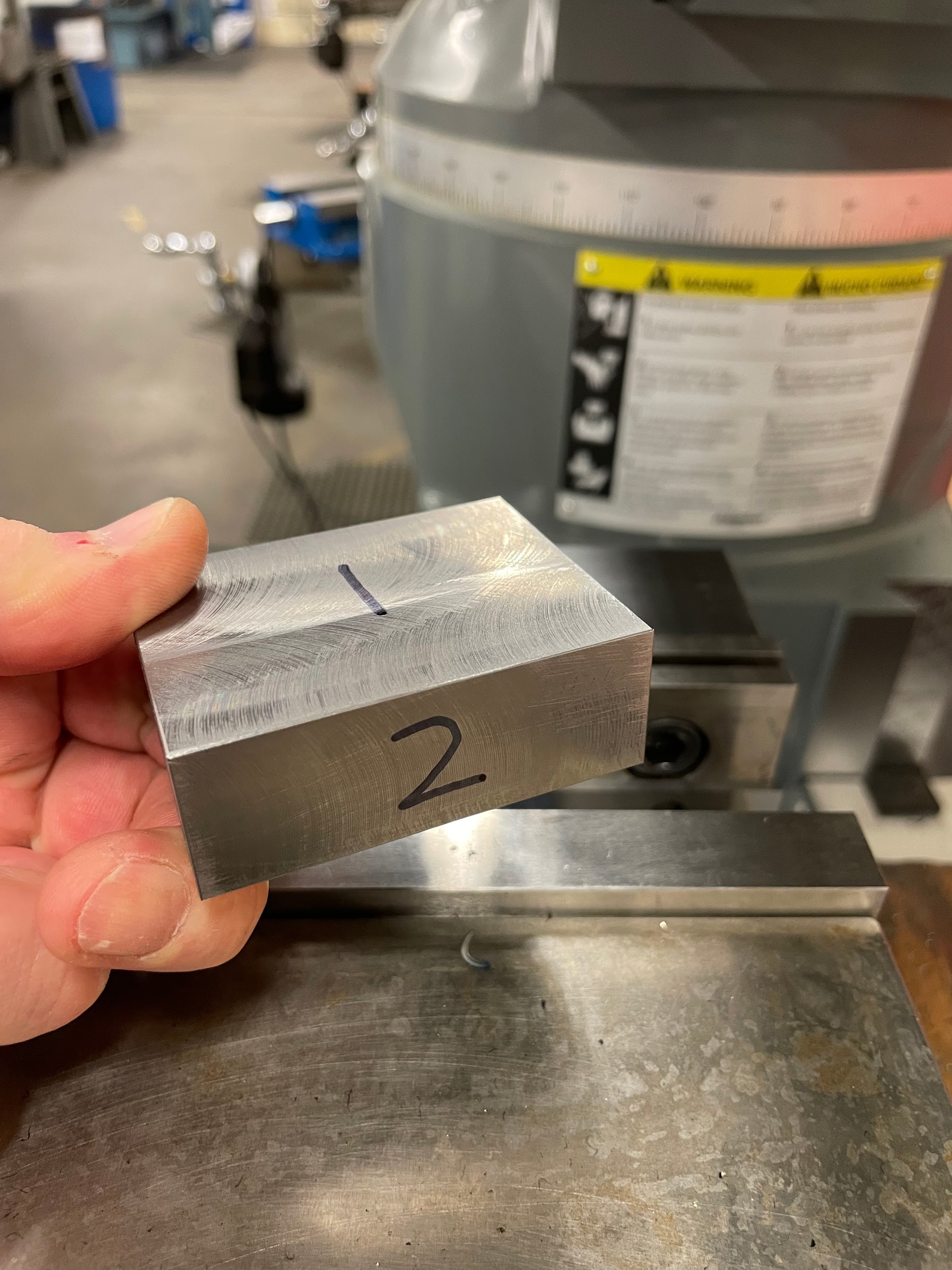
- Load the block of material back into the milling vise, with side one against the solid jaw and the second largest side in preparation to be faced.
- Place the part on a single parallel.
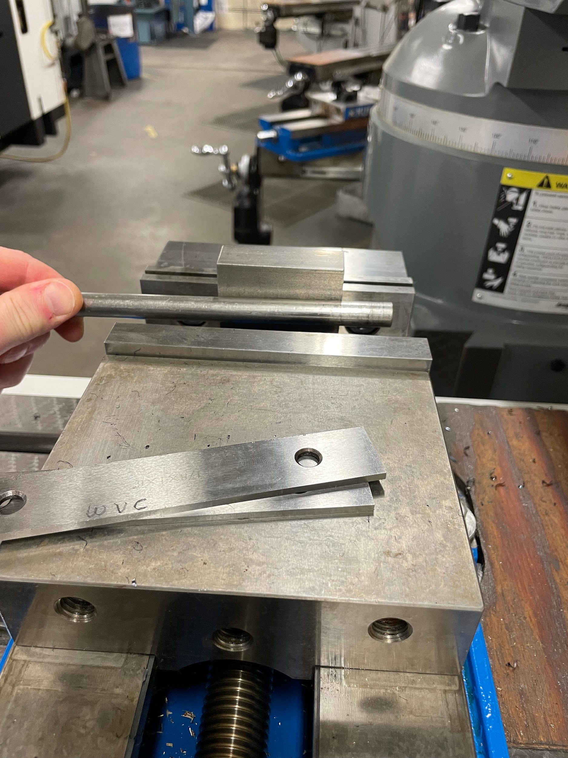
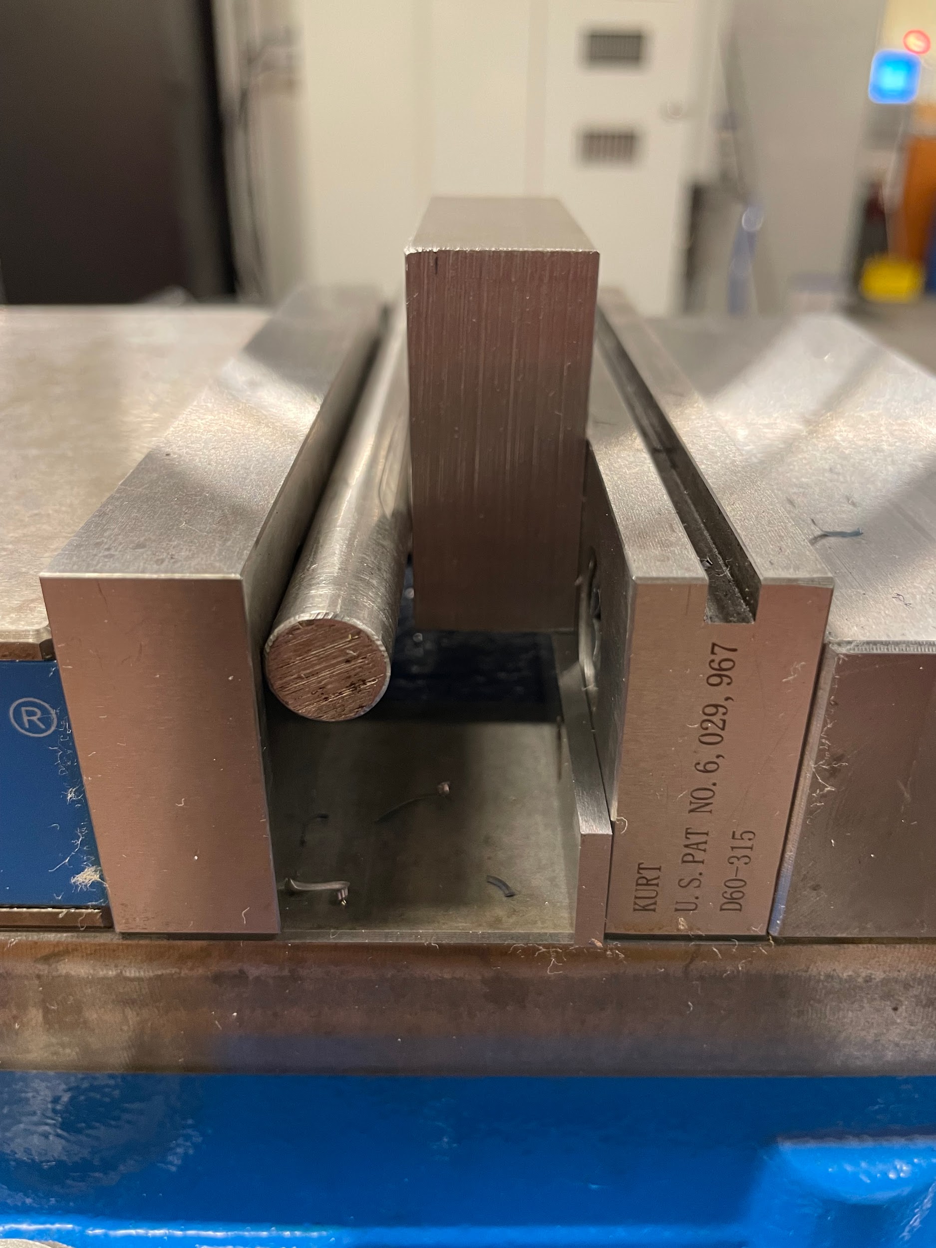
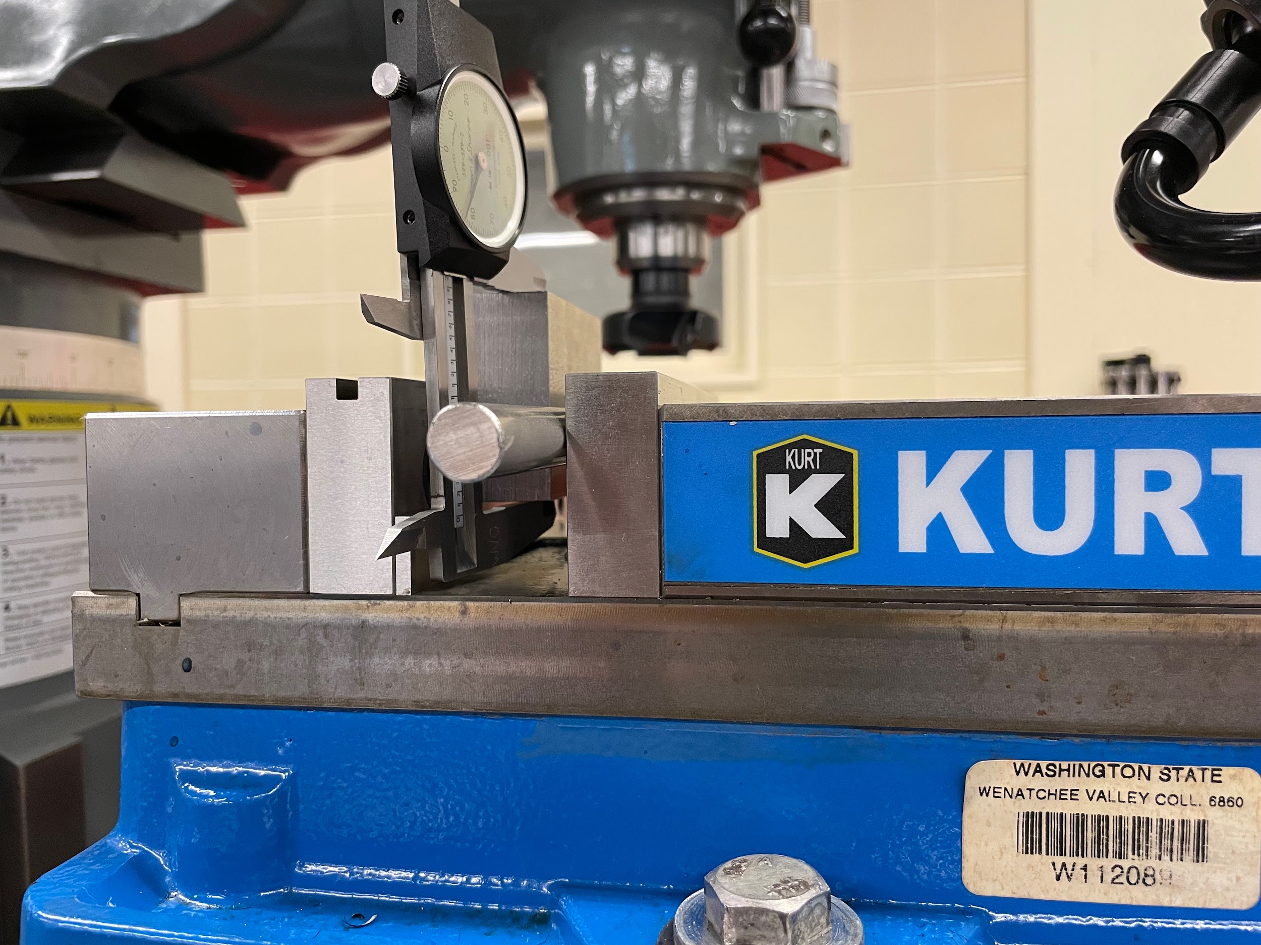
- Use a round bar in between the movable jaw and the part when clamping.
- The reason for the bar and the single parallel is to make sure the part conforms to sitting flat against the solid jaw plate and not the movable jaw plate or a pair of parallels.
- Take a 1/64″ to 1/32″ facing cut to clean the surface.
- Remove the part and deburr all edges.
- Side three
- Load the block of material back into the milling vise, with side one against the solid jaw and side two against the single parallel.
- Use a round bar in between the movable jaw and the part when clamping.
- Tap the part down tight against the parallel.
- Take appropriate roughing and finishing facing cuts to bring the part to size.
- Remove the part and deburr all edges.
- Side four
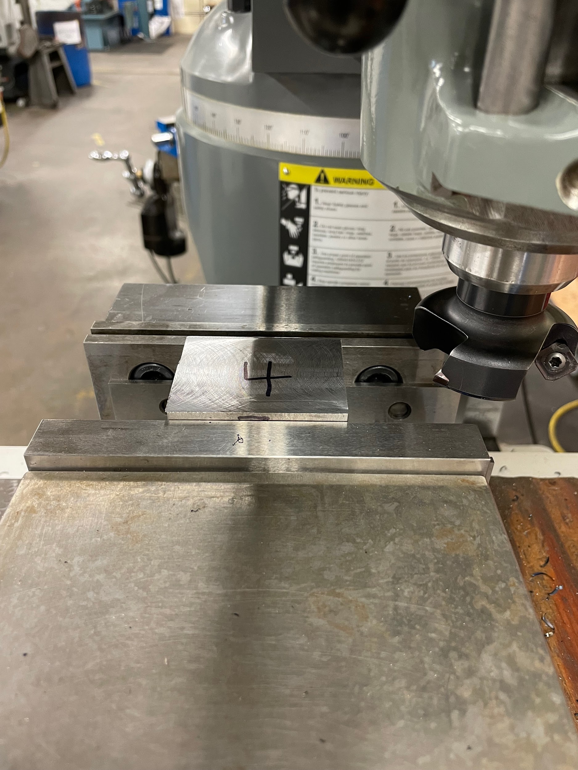
- Load the block of material back into the milling vise, with side one against a pair of parallels and side two against the solid jaw.
- Do not use a round bar.
- Tap the part down tight against the parallels.
- Take appropriate roughing and finishing facing cuts to bring the part to size.
- Remove the part and deburr all edges.
- Side five
- Load the block of material back into the milling vise, with side one against the solid jaw and the third largest side in preparation to be faced.
- Place the part on a single parallel.
- Use a round bar in between the movable jaw and the part when clamping.
- Clamp gently.
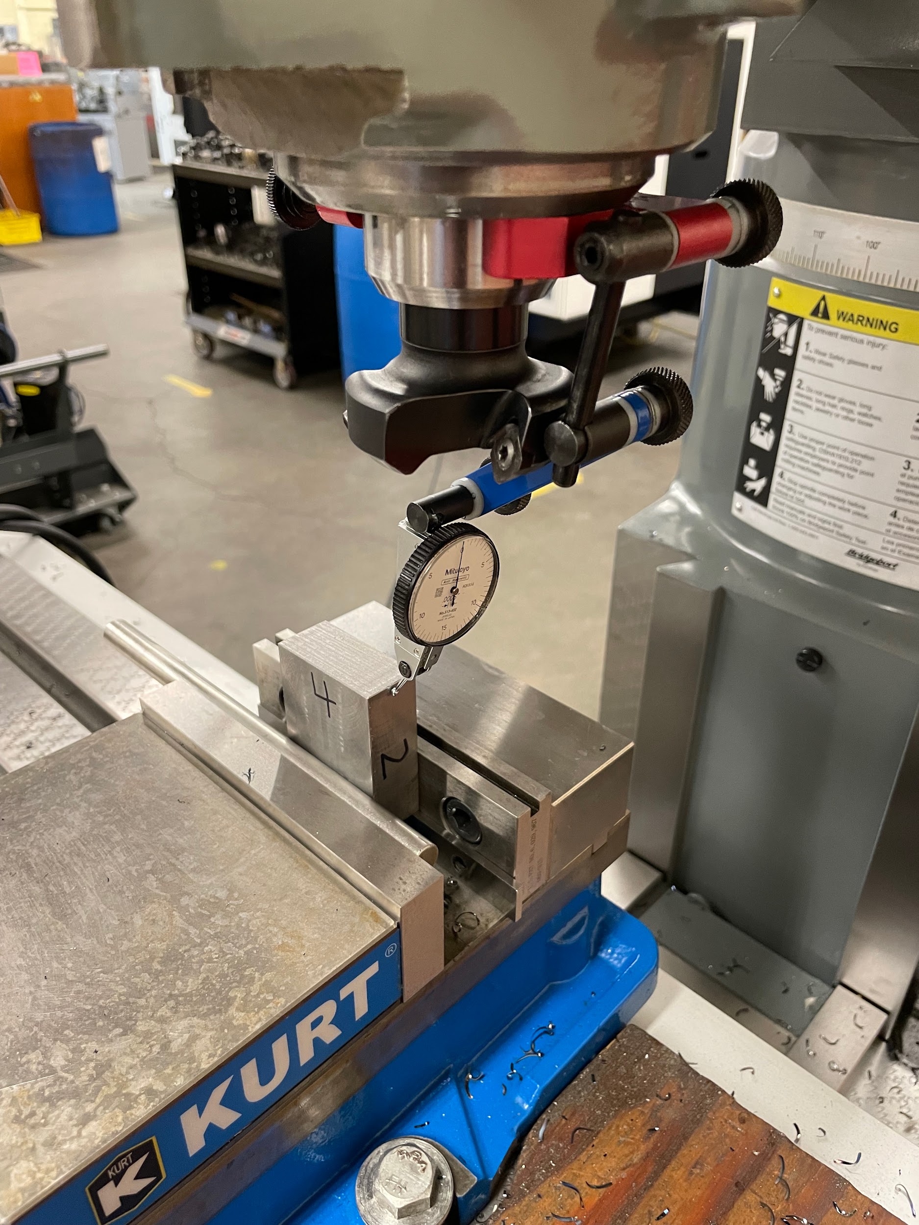
- Use an indicator to dial the side of the part straight up and down. Tap it with a hammer to move it slightly.
- Fully tighten the vise.
- Take a 1/64″ to 1/32″ facing cut to clean the surface.
- Remove the part and deburr all edges.
- Side six
- Load the block of material back into the milling vise, with side one against the solid jaw and side five against the single parallel.
- Use a round bar in between the movable jaw and the part when clamping.
- Tap the part down tight against the parallel.
- Take appropriate roughing and finishing facing cuts to bring the part to size.
- Remove the part and deburr all edges.
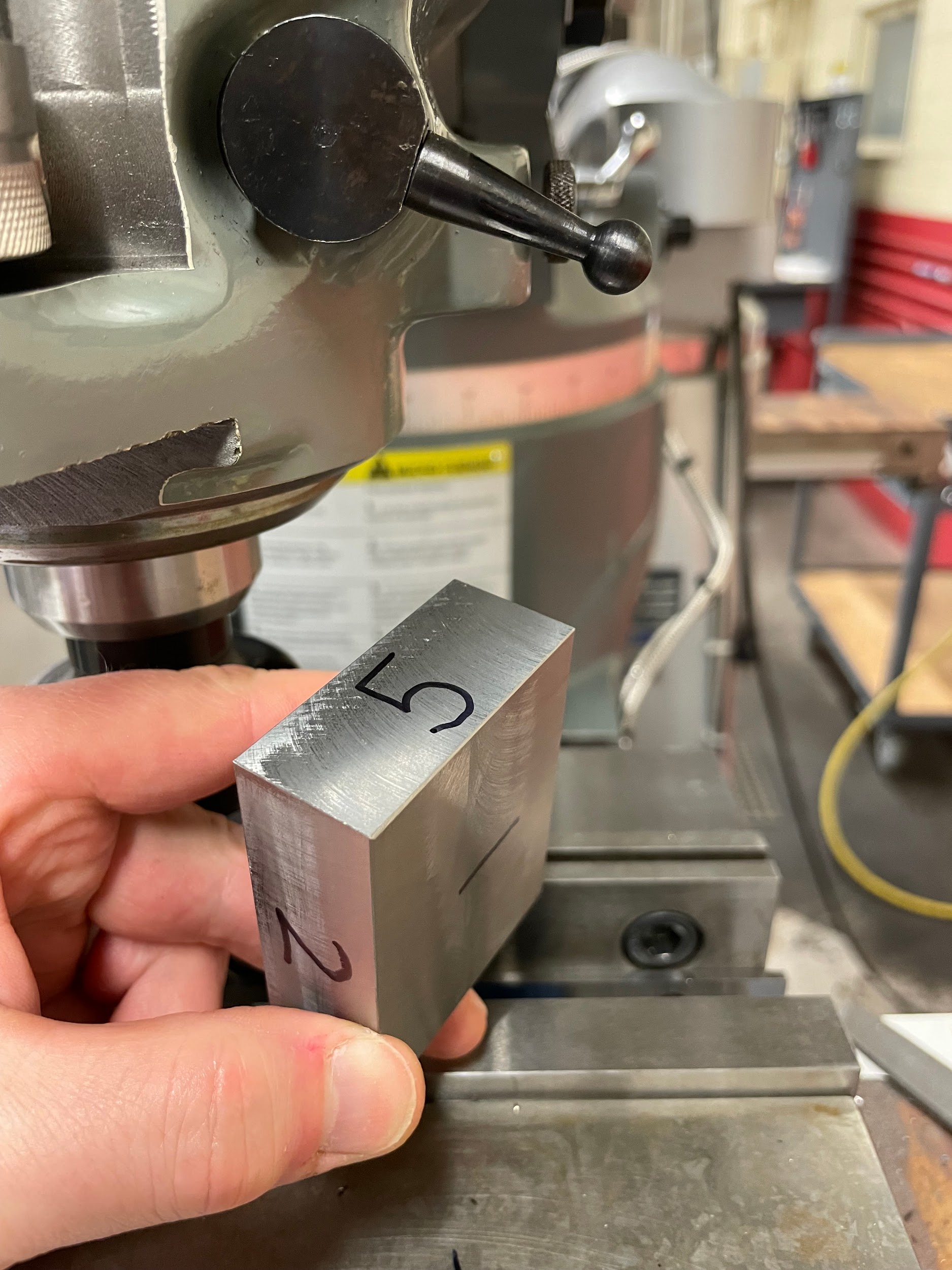
Step 1-e: Remove the part and deburr all edges.
Step 1-e: Remove the part and deburr all edges.
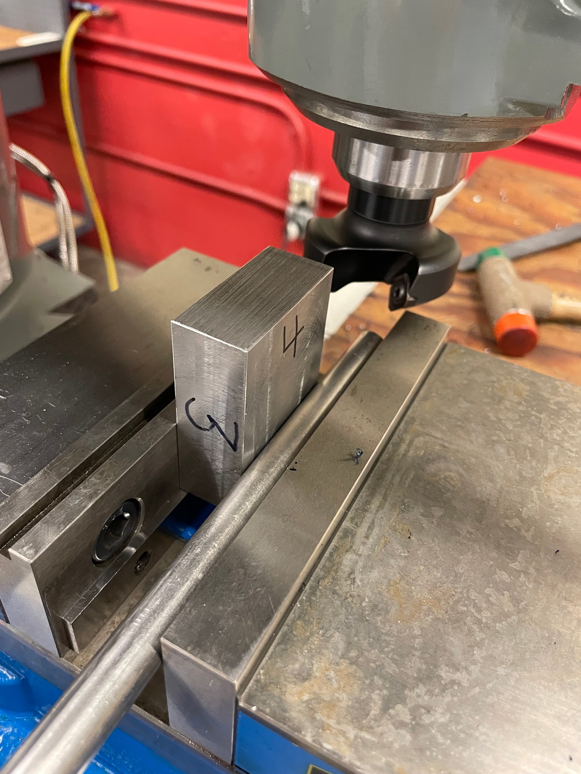
Step 2-c: Use a round bar in between the movable jaw and the part when clamping.
Step 2-c: Use a round bar in between the movable jaw and the part when clamping.
Step 2-e: Take a 1/64″ to 1/32″ facing cut to clean the surface.

Step 2-e: Take a 1/64″ to 1/32″ facing cut to clean the surface.

Step 2-f: Remove the part and deburr all edges.
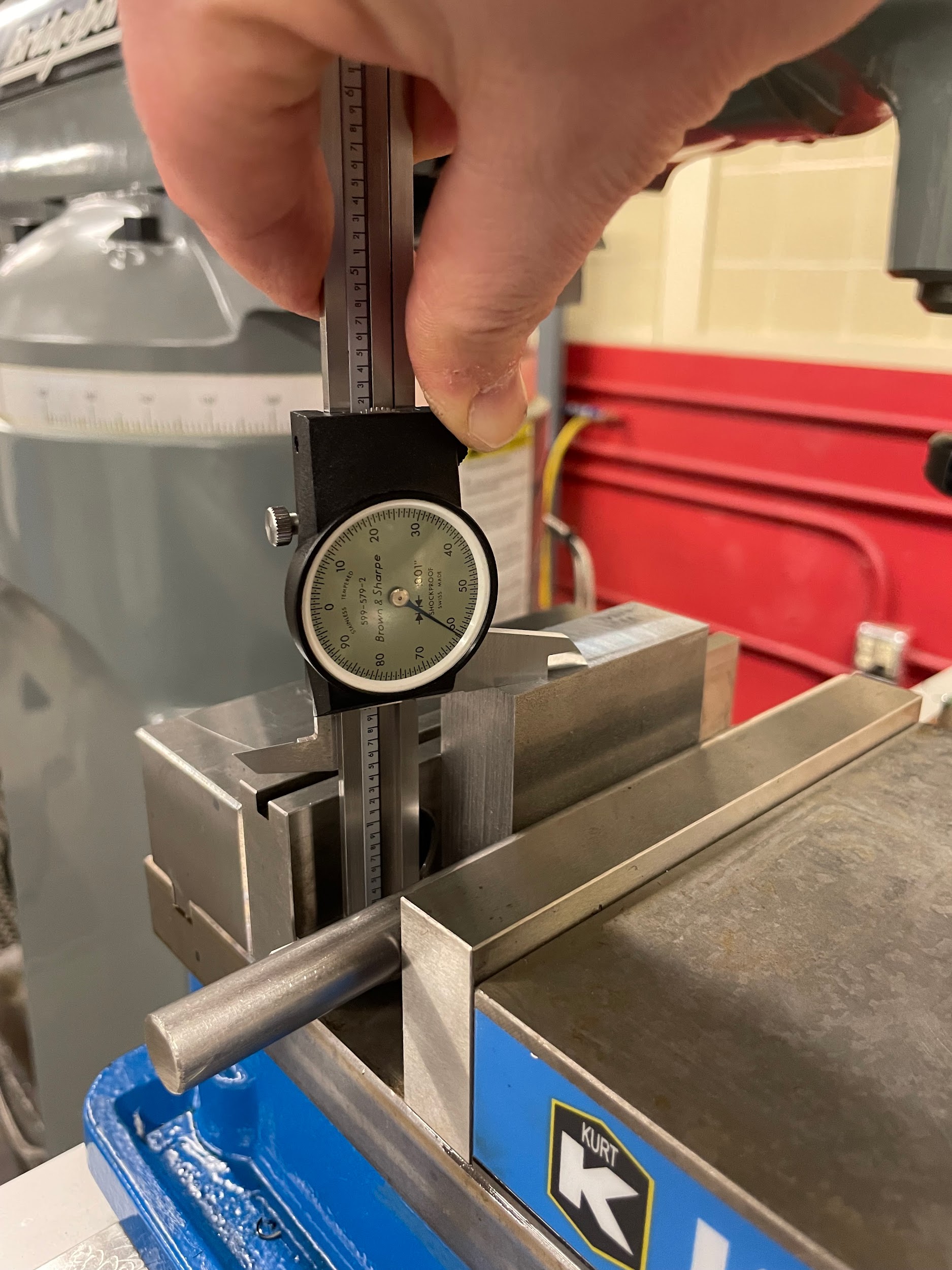
Step 3-d: Take appropriate roughing and finishing facing cuts to bring the part to size.

Step 3-d: Take appropriate roughing and finishing facing cuts to bring the part to size.
Step 3-d: Take appropriate roughing and finishing facing cuts to bring the part to size.
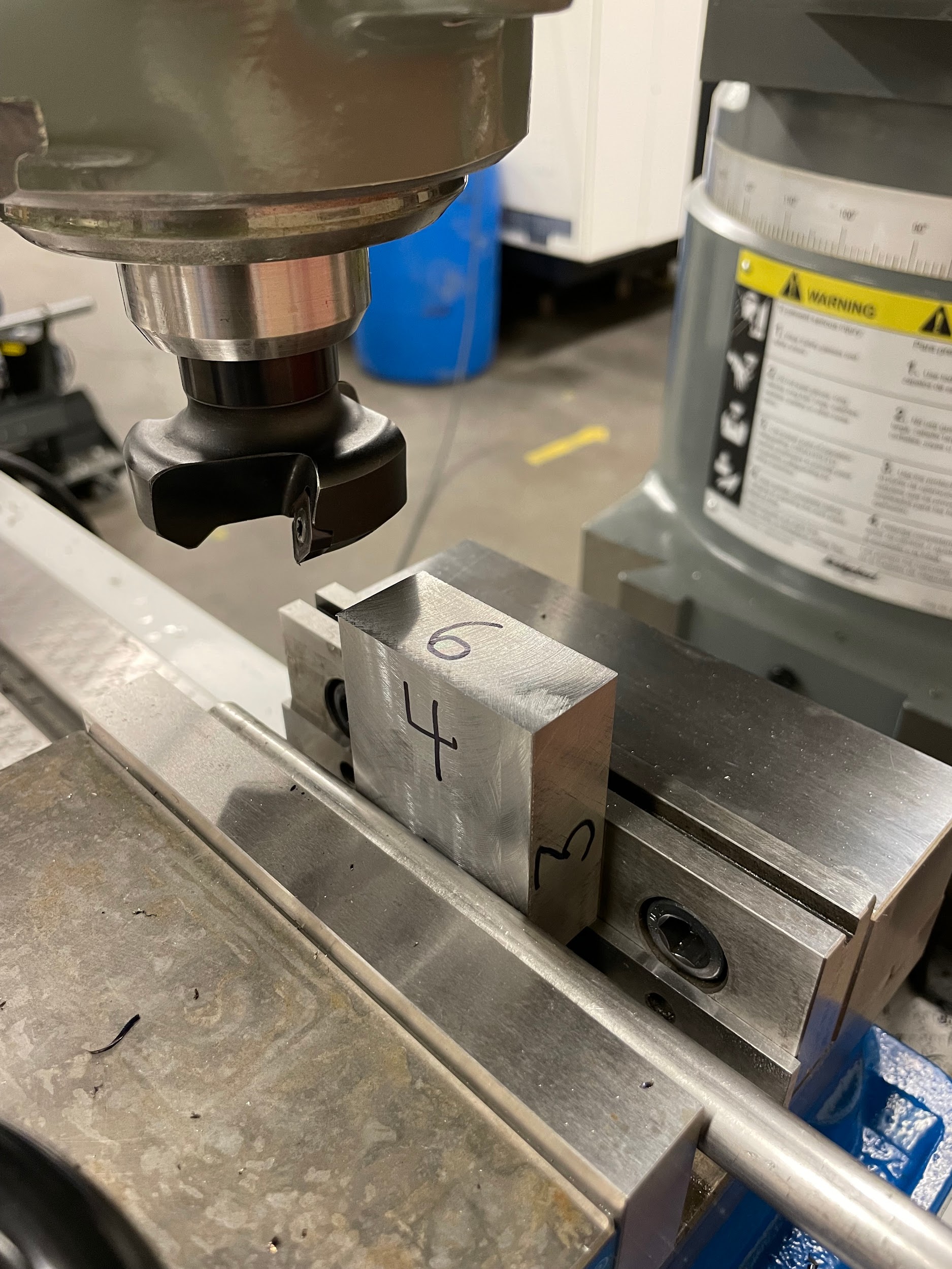
Step 4-a-c: Load the block of material back into the milling vise, with side one against a pair of parallels and side two against the solid jaw. Do not use a round bar. Tap the part down tight against the parallels.

Step 4-d: Take appropriate roughing and finishing facing cuts to bring the part to size.
Step 5-c: Use a round bar in between the movable jaw and the part when clamping.
Step 5-e: Use an indicator to dial the side of the part straight up and down. Tap it with a hammer to move it slightly.
Step 5-e: Use an indicator to dial the side of the part straight up and down. Tap it with a hammer to move it slightly.

Step 5-e: Use an indicator to dial the side of the part straight up and down. Tap it with a hammer to move it slightly.

Step 5-e: Use an indicator to dial the side of the part straight up and down. Tap it with a hammer to move it slightly.

Step 5-e: Use an indicator to dial the side of the part straight up and down. Tap it with a hammer to move it slightly.

Step 5-g: Take a 1/64″ to 1/32″ facing cut to clean the surface.

Step 5-h: Remove the part and deburr all edges.
Step 6-d: Take appropriate roughing and finishing facing cuts to bring the part to size.
Alternative side five and six steps for block squaring:
- Side five alternate
- Load a large end mill into the spindle.
- Load the block of material back into the milling vise, with side one against a pair of parallels and side two against the solid jaw. Let side five overhang the side of the vise.
- Tap the part down tight against the parallels.
- Take 1/64″ to 1/32″ material off using end mill side passes to clean the surface. One rough, one finish.
- Remove the part and deburr all edges.
- Side six alternate
- Load the block of material back into the milling vise, with side one against a pair of parallels and side two against the solid jaw. Let side six overhang the side of the vise.
- Tap the part down tight against the parallels.
- Take appropriate roughing and finishing side cuts to bring the part to size.
- Remove the part and deburr all edges.
Attributions
- Figure 9.148: Deburring the edges of a faced part by Micky R. Jennings, courtesy of Wenatchee Valley College, for WA Open ProfTech, © SBCTC, CC BY 4.0
- Figure 9.149: Side one complete by Micky R. Jennings, courtesy of Wenatchee Valley College, for WA Open ProfTech, © SBCTC, CC BY 4.0
- Figure 9.150: Round bar by Micky R. Jennings, courtesy of Wenatchee Valley College, for WA Open ProfTech, © SBCTC, CC BY 4.0
- Figure 9.151: Round bar 2 by Micky R. Jennings, courtesy of Wenatchee Valley College, for WA Open ProfTech, © SBCTC, CC BY 4.0
- Video 9.28: Micky R. Jennings, courtesy of Wenatchee Valley College, for WA Open ProfTech, © SBCTC, CC BY 4.0
- Video 9.29: Micky R. Jennings, courtesy of Wenatchee Valley College, for WA Open ProfTech, © SBCTC, CC BY 4.0
- Figure 9.152: Side two complete by Micky R. Jennings, courtesy of Wenatchee Valley College, for WA Open ProfTech, © SBCTC, CC BY 4.0
- Video 9.30: Micky R. Jennings, courtesy of Wenatchee Valley College, for WA Open ProfTech, © SBCTC, CC BY 4.0
- Figure 9.153: Measuring after side three by Micky R. Jennings, courtesy of Wenatchee Valley College, for WA Open ProfTech, © SBCTC, CC BY 4.0
- Figure 9.154: Measuring after side three by Micky R. Jennings, courtesy of Wenatchee Valley College, for WA Open ProfTech, © SBCTC, CC BY 4.0
- Video 9.31: Micky R. Jennings, courtesy of Wenatchee Valley College, for WA Open ProfTech, © SBCTC, CC BY 4.0
- Figure 9.155: Side four faced by Micky R. Jennings, courtesy of Wenatchee Valley College, for WA Open ProfTech, © SBCTC, CC BY 4.0
- Figure 9.156: Side five facing setup by Micky R. Jennings, courtesy of Wenatchee Valley College, for WA Open ProfTech, © SBCTC, CC BY 4.0
- Figure 9.157: Indicating for side five by Micky R. Jennings, courtesy of Wenatchee Valley College, for WA Open ProfTech, © SBCTC, CC BY 4.0
- Video 9.32: Micky R. Jennings, courtesy of Wenatchee Valley College, for WA Open ProfTech, © SBCTC, CC BY 4.0
- Video 9.33: Micky R. Jennings, courtesy of Wenatchee Valley College, for WA Open ProfTech, © SBCTC, CC BY 4.0
- Video 9.34: Micky R. Jennings, courtesy of Wenatchee Valley College, for WA Open ProfTech, © SBCTC, CC BY 4.0
- Video 9.35: Micky R. Jennings, courtesy of Wenatchee Valley College, for WA Open ProfTech, © SBCTC, CC BY 4.0
- Video 9.36: Micky R. Jennings, courtesy of Wenatchee Valley College, for WA Open ProfTech, © SBCTC, CC BY 4.0
- Figure 9.158: Side Five Complete by Micky R. Jennings, courtesy of Wenatchee Valley College, for WA Open ProfTech, © SBCTC, CC BY 4.0
- Figure 9.159: Side six faced by Micky R. Jennings, courtesy of Wenatchee Valley College, for WA Open ProfTech, © SBCTC, CC BY 4.0
The process of systematically cutting the six sides of a block square to one another.
