9.12 Side Milling
Micky R. Jennings

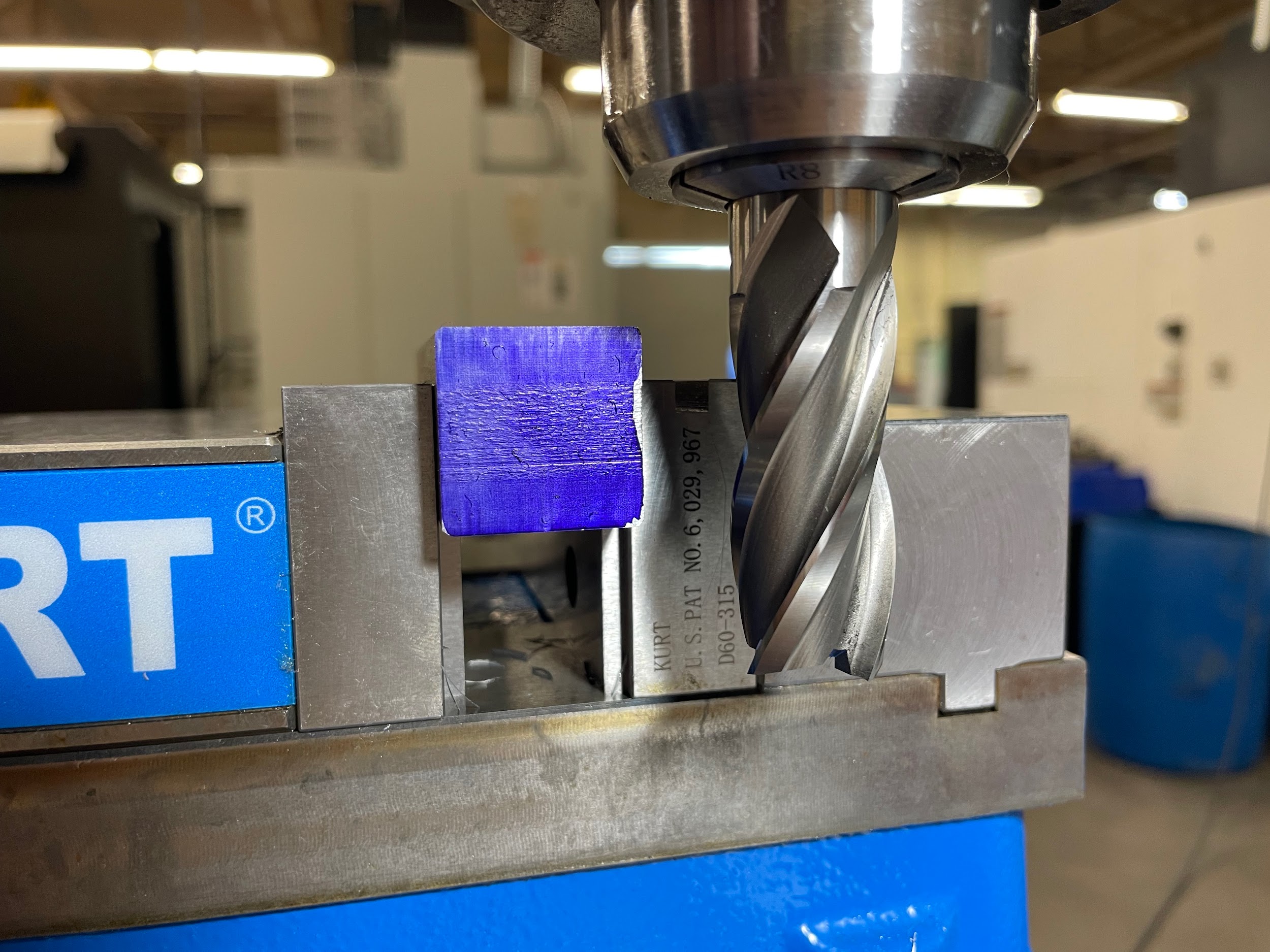
Figure 9.160. A side view of a part secured in a vise in preparation for side milling. The part has layout dye on the side that is to be cut. An end mill is positioned close to the part on the right. / Image Credit: Micky R. Jennings, courtesy of Wenatchee Valley College, CC BY 4.0
Side milling is the process of using an end mill to create features on a part. Side milling is generally performed in a sideways motion, utilizing the periphery of the tool to make the cut. Plunging motions can be performed with an end mill if the tool is center cutting, but this movement isn’t as efficient and should be done lightly to keep from loading the flutes at the end of the tool.
Step by step process for side milling:
- Load an end mill into the milling machine using a solid holder or a spring collet. When putting a tool into a collet, make sure to choke up on as much of the shank as possible without the collet going over the flutes. Clamping the tool within 1/8″ of the flutes will help with tool rigidity.
- Lock the quill.
- Load stock into the vise on parallels. Select parallels to clamp on as much material as the cut will allow. Doing so increases rigidity in the part.
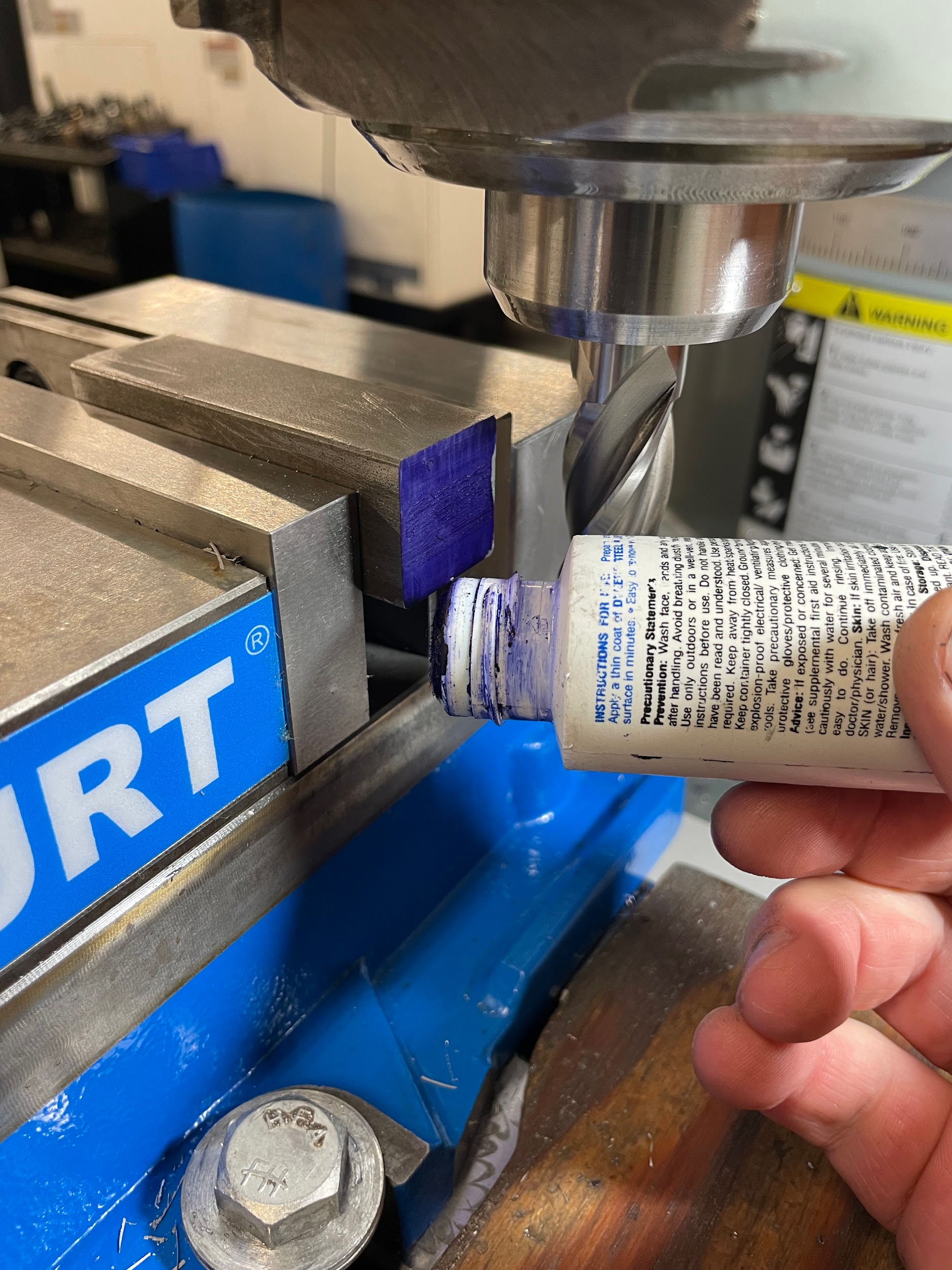
- Apply layout dye to the side of the part to be machined. This will allow the operator to see the tool touching off on the work better.
- Raise the knee and position the work using the saddle and table to just above the part.
- Calculate RPM for the end mill, turn on the spindle, and adjust to the correct speed.
- Gently raise the knee until the edges of the end mill touch the top of the work.
- Zero the graduated collar on the knee handle.
- Move the tool fully off the edge of the part.
- Move the knee up to the desired depth.
- Move the table until the tool touches the side of the part.
- Zero the graduated collar of the table handwheel.
- Move the work off to one side in preparation for making a conventional milling cut.
- Move the table in by the desired depth of cut.
- Lock the table movement in that direction.
- Apply a small amount of cutting oil to the surface that will be milled.
- Feed the part across the cutter to complete the cut.
- Inspect the cut for full clean up
- Adjust the table another .005″
- Climb mill back across the part.
- Turn off the spindle.
- Inspect cut and repeat if necessary.
- Flip the part end for end and repeat.
- Touch off, alternatively, with paper on this side.
- Make conventional roughing cuts to within .005″ to .010
- Make one finish climb cut to size.
Step 4: Apply layout dye to the side of the part to be machined. This will allow the operator to see the tool touching off on the work better.
Step 4: Apply layout dye to the side of the part to be machined. This will allow the operator to see the tool touching off on the work better.
Step 11: Move the table until the tool touches the side of the part.

Step 16: Apply a small amount of cutting oil to the surface that will be milled.

Step 16: Apply a small amount of cutting oil to the surface that will be milled.

Step 17: Feed the part across the cutter to complete the cut.

Step 20: Climb mill back across the part.

Step 24: Touch off, alternatively, with paper on this side.

Step 26: Make one finish climb cut to size.
Attributions
- Figure 9.160: Side milling by Micky R. Jennings, courtesy of Wenatchee Valley College, for WA Open ProfTech, © SBCTC, CC BY 4.0
- Figure 9.161: Applying layout dye by Micky R. Jennings, courtesy of Wenatchee Valley College, for WA Open ProfTech, © SBCTC, CC BY 4.0
- Figure 9.162: Layout dye by Micky R. Jennings, courtesy of Wenatchee Valley College, for WA Open ProfTech, © SBCTC, CC BY 4.0
- Video 9.37: Micky R. Jennings, courtesy of Wenatchee Valley College, for WA Open ProfTech, © SBCTC, CC BY 4.0
- Video 9.38: Micky R. Jennings, courtesy of Wenatchee Valley College, for WA Open ProfTech, © SBCTC, CC BY 4.0
- Video 9.39: Micky R. Jennings, courtesy of Wenatchee Valley College, for WA Open ProfTech, © SBCTC, CC BY 4.0
- Video 9.40: Micky R. Jennings, courtesy of Wenatchee Valley College, for WA Open ProfTech, © SBCTC, CC BY 4.0
- Video 9.41: Micky R. Jennings, courtesy of Wenatchee Valley College, for WA Open ProfTech, © SBCTC, CC BY 4.0
- Video 9.42: Micky R. Jennings, courtesy of Wenatchee Valley College, for WA Open ProfTech, © SBCTC, CC BY 4.0
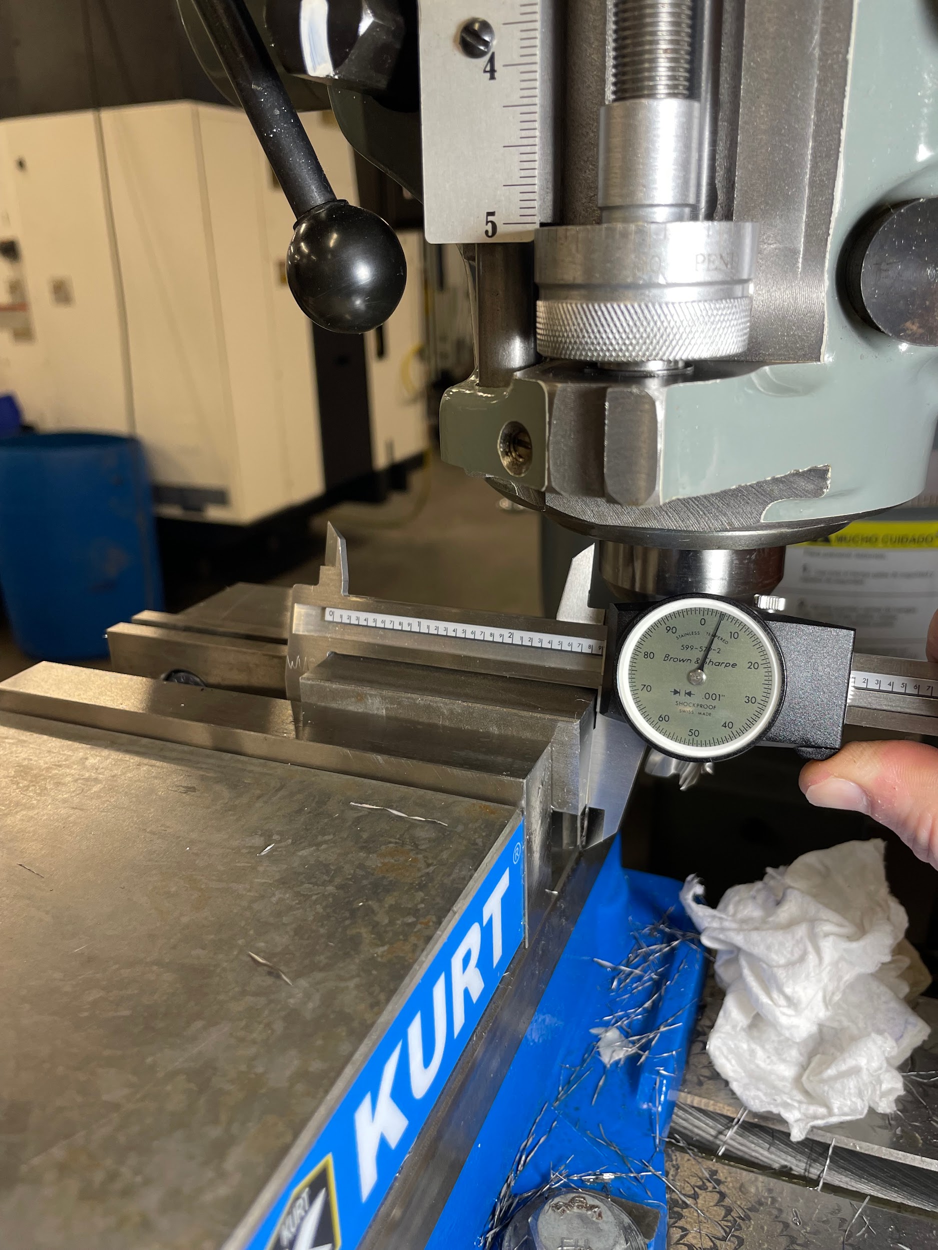
- Figure 9.163: Measuring the overall length by Micky R. Jennings, courtesy of Wenatchee Valley College, for WA Open ProfTech, © SBCTC, CC BY 4.0
The process of using the side of an end mill to cut vertical surfaces.
