9.13 Slotting
Micky R. Jennings

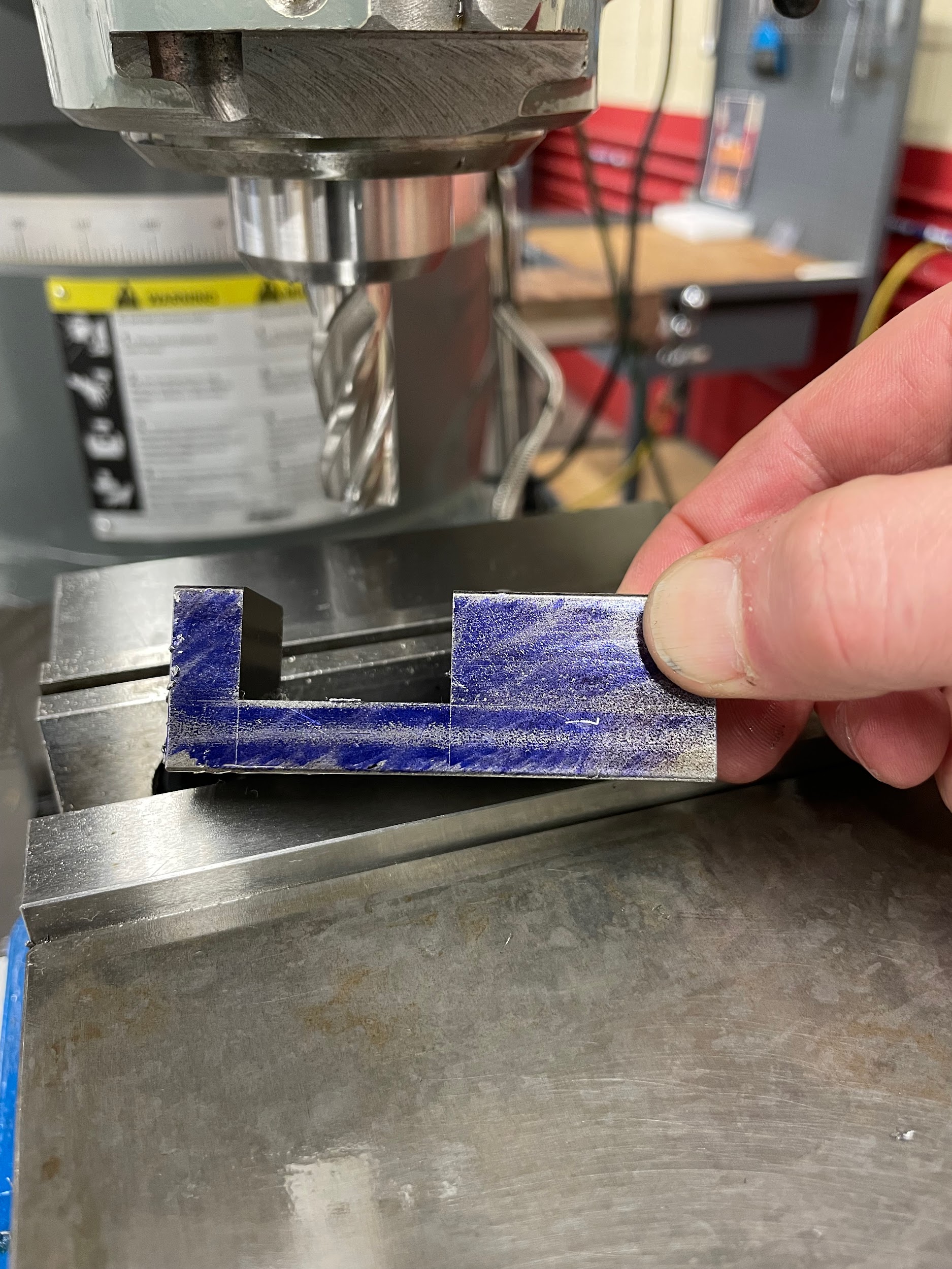
Figure 9.164. A hand holds a rectangular part that has a finished slot cut on one end. / Image Credit: Micky R. Jennings, courtesy of Wenatchee Valley College, CC BY 4.0
Slotting is the process of using an end mill to create a slot or groove in a part. A precision slot is generally performed in multiple passes, allowing the operator to adjust the machine for position and size. Attempting a slot in a single pass may result in an oversized and out-of-position slot that has a poor surface finish.
Step by step process slotting:
- Load material into a vise.
- Apply layout dye to the top of the part.
- Using odd legged calipers, scribe lines on the top of the part to indicate the position of the slot.
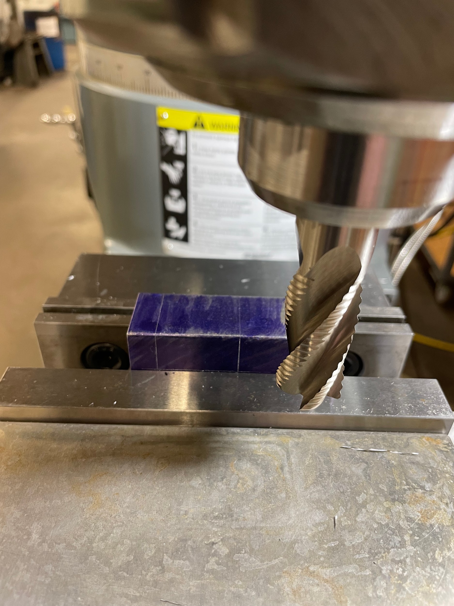
- Load an end mill for roughing, one size smaller than the slot, into the milling machine.
- Calculate the spindle speed and feed rate for the cut.
- Turn the spindle on and adjust the machine to the calculated speed.
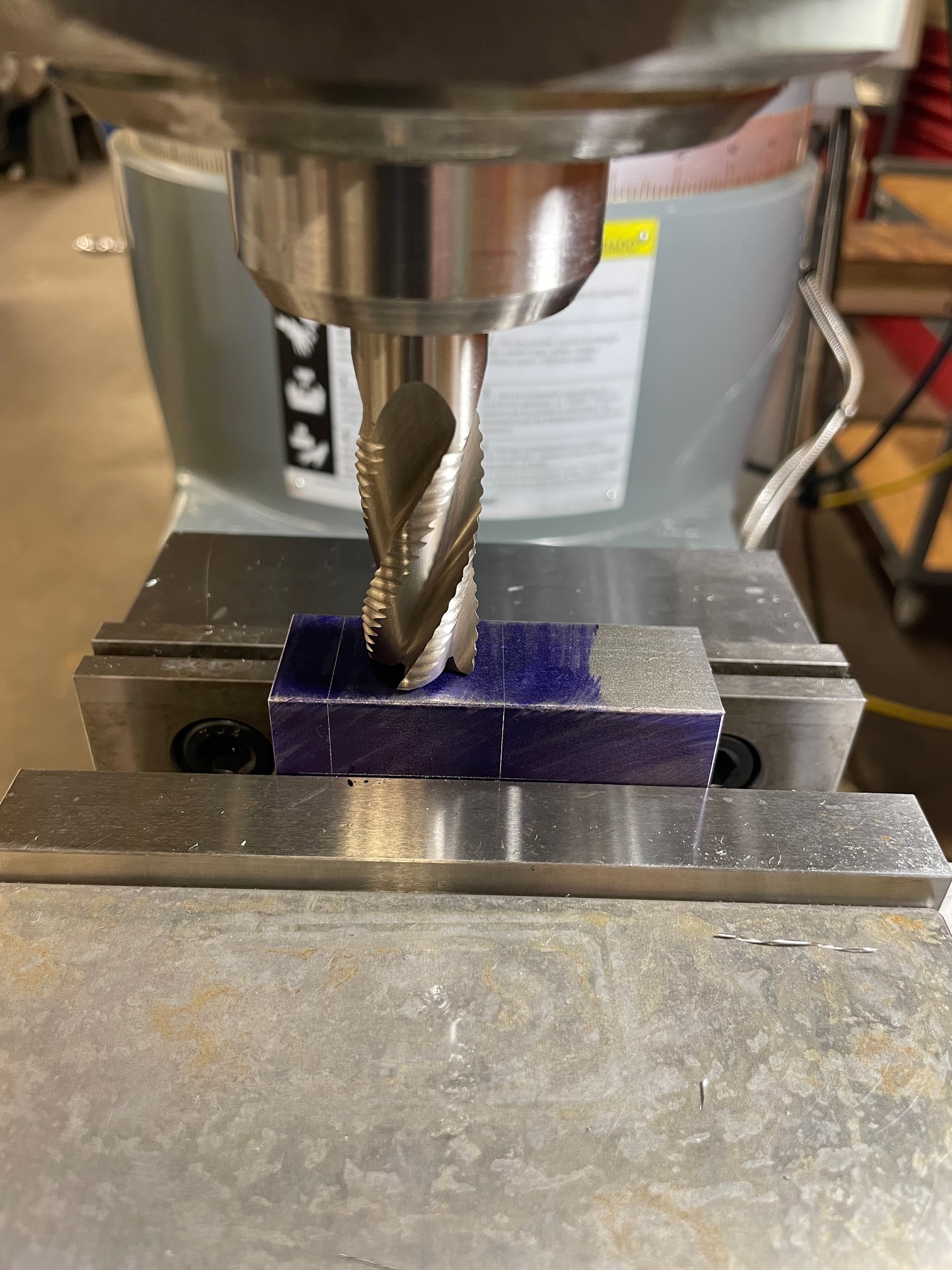
- Position the machine so that the tool is visually in the center of the slot.
- Zero and lock the table handwheel.
- Touch the tool off to the top of the work.
- Set the graduated collar of the knee to zero.
- Move the saddle so the tool is off the work.
- Move the knee up the desired depth of cut, minus .015″.
- Lube the tool and the work.
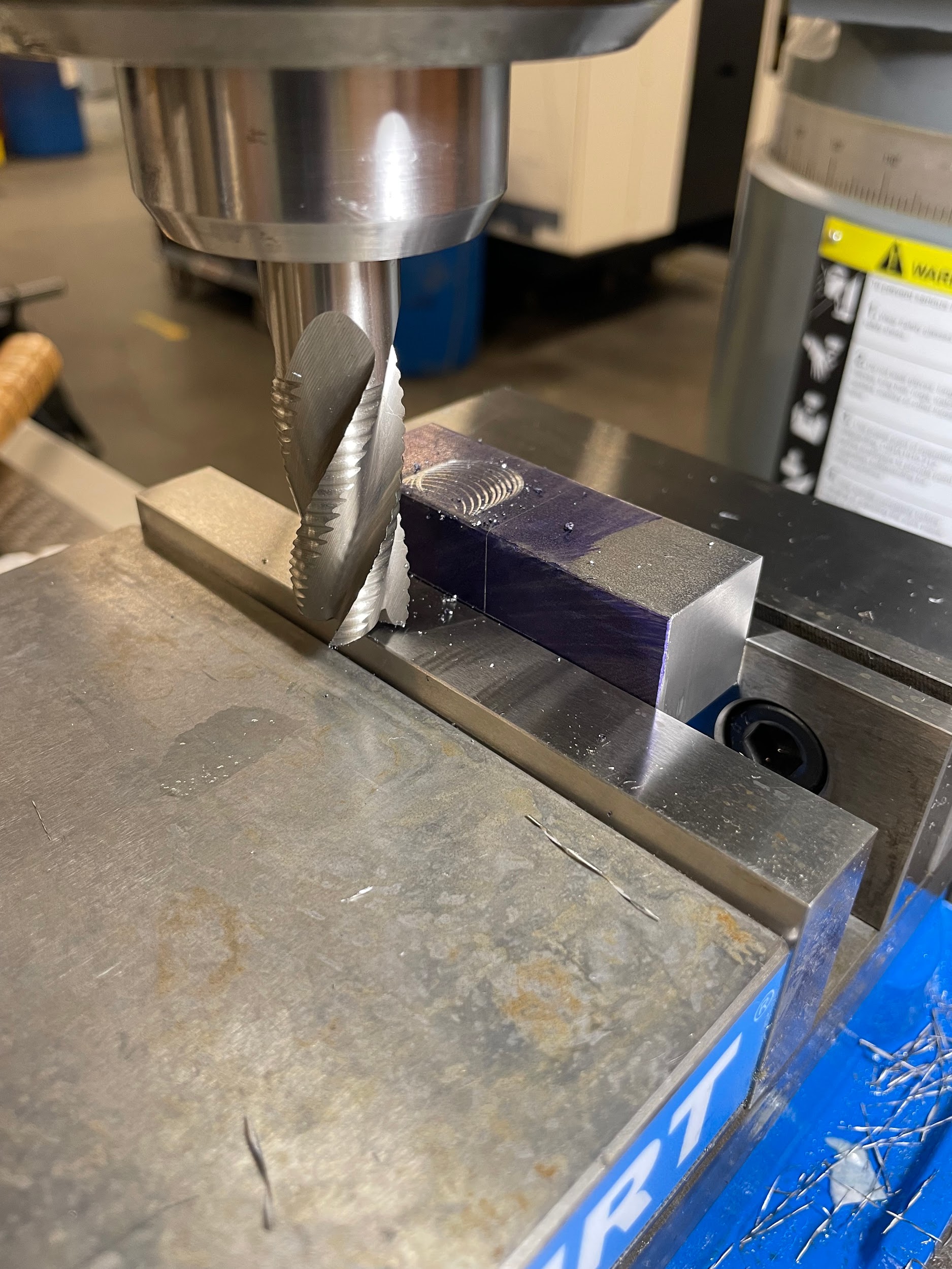
- Make the initial cut through the length of the slot at the calculated feed rate.
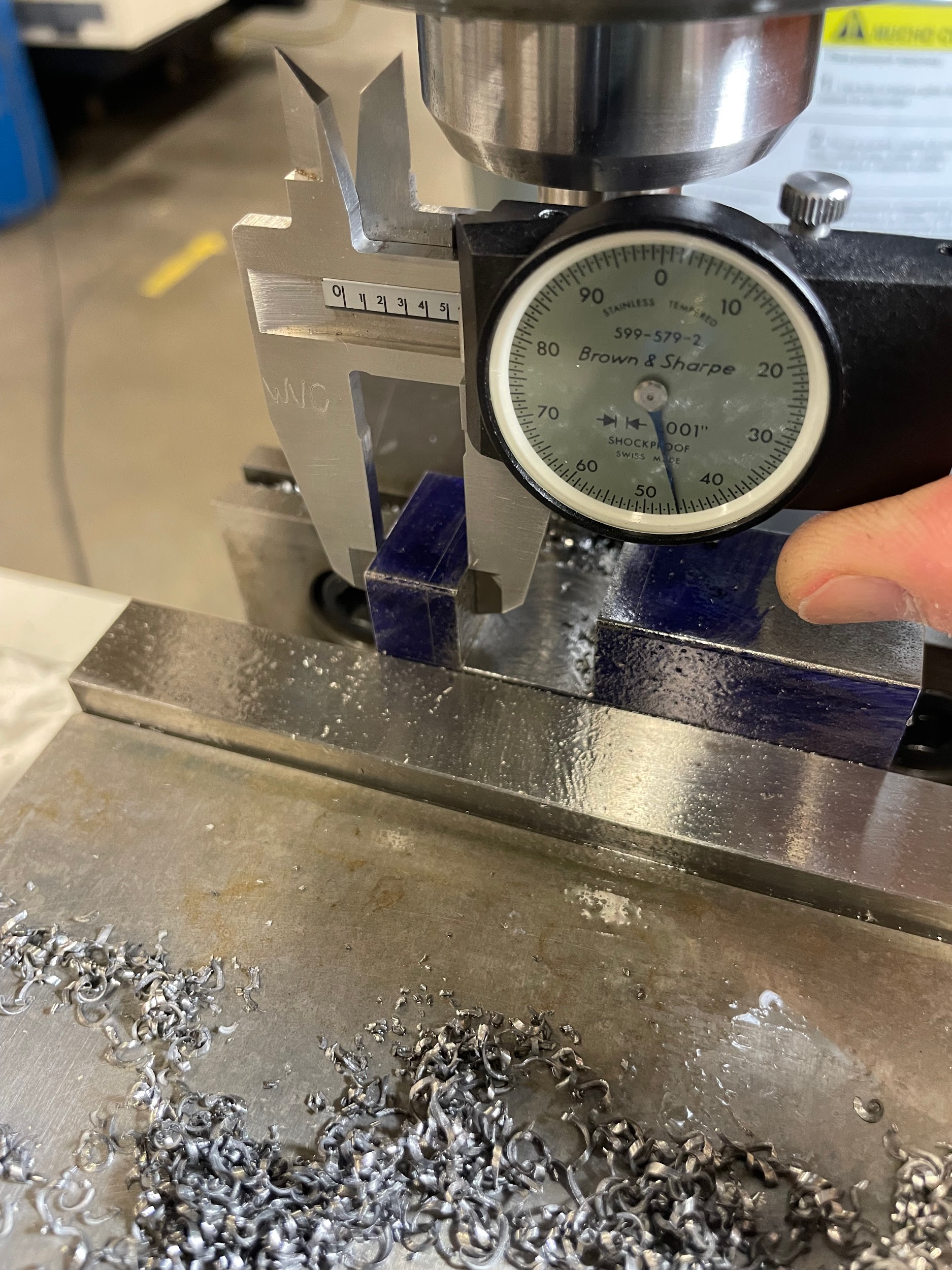
- Take a measurement to determine the amount needed to be removed in one direction.
- Conventional cut the remaining material, leaving material on walls for finishing.
- Load a separate finishing tool if needed.
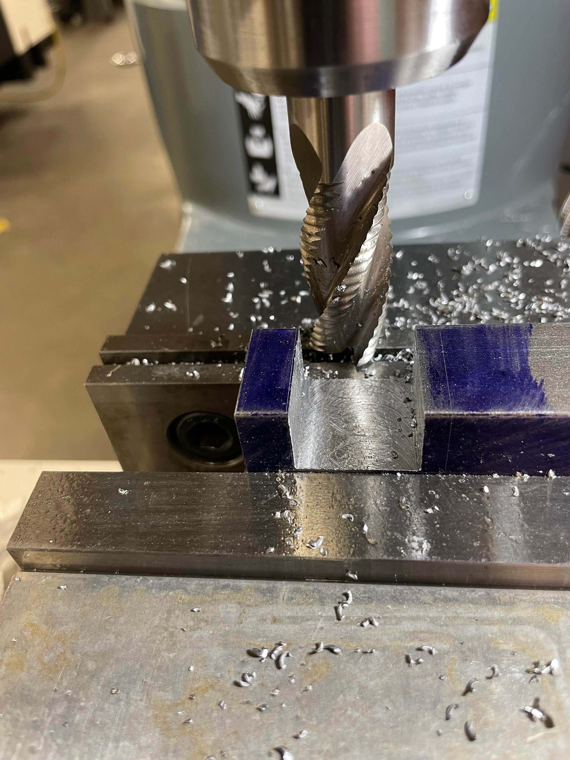
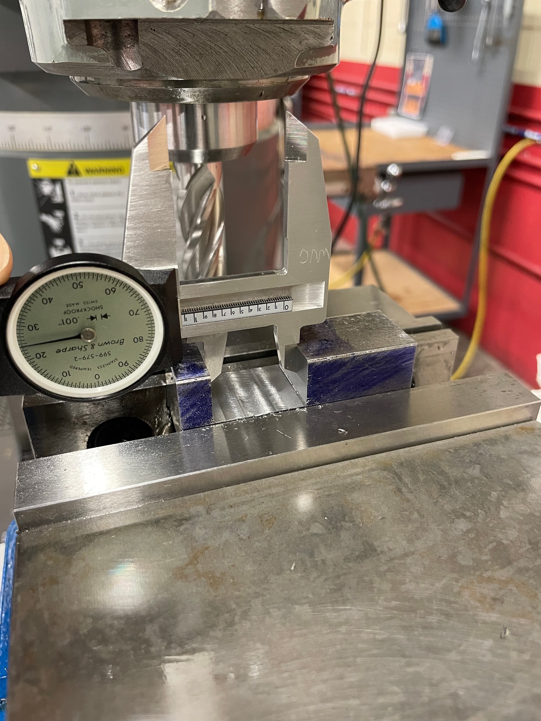
- Make a test cut just skimming the bottom and the side of the slot.
- Zero the table and knee handwheels.
- Accurately measure the part.
- Set the knee to the full depth of the slot.
- Adjust the machine and make successive cuts in order to finish one side.
- Make a skim cut on the other side of the slot.
- Zero the table handwheel.
- Measure the slot and calculate the material needed to be removed to finish the slot.
- Adjust the machine and make successive cuts in order to finish the slot.
Step 4: Load an end mill for roughing, one size smaller than the slot, into the milling machine.
Step 7: Position the machine so that the tool is visually in the center of the slot.
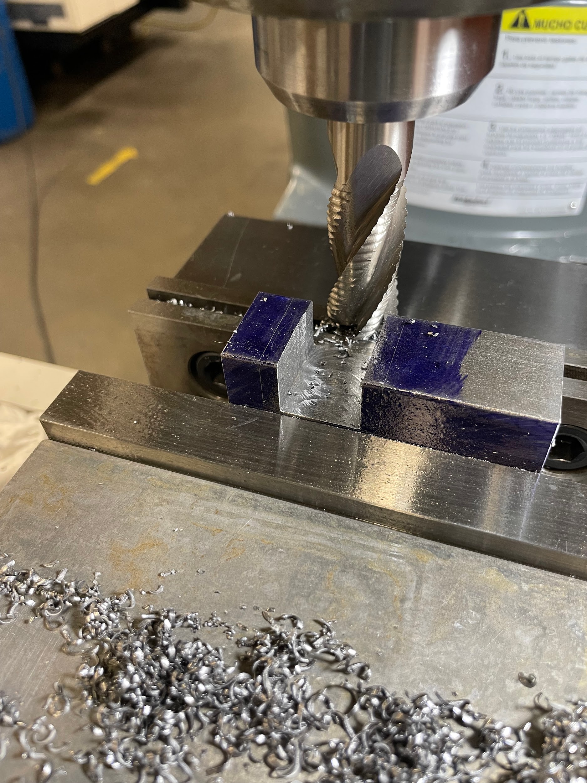
Step 9: Touch the tool off to the top of the work.

Step 12: Move the knee up the desired depth of cut, minus .015″.
Step 13: Lube the tool and the work.
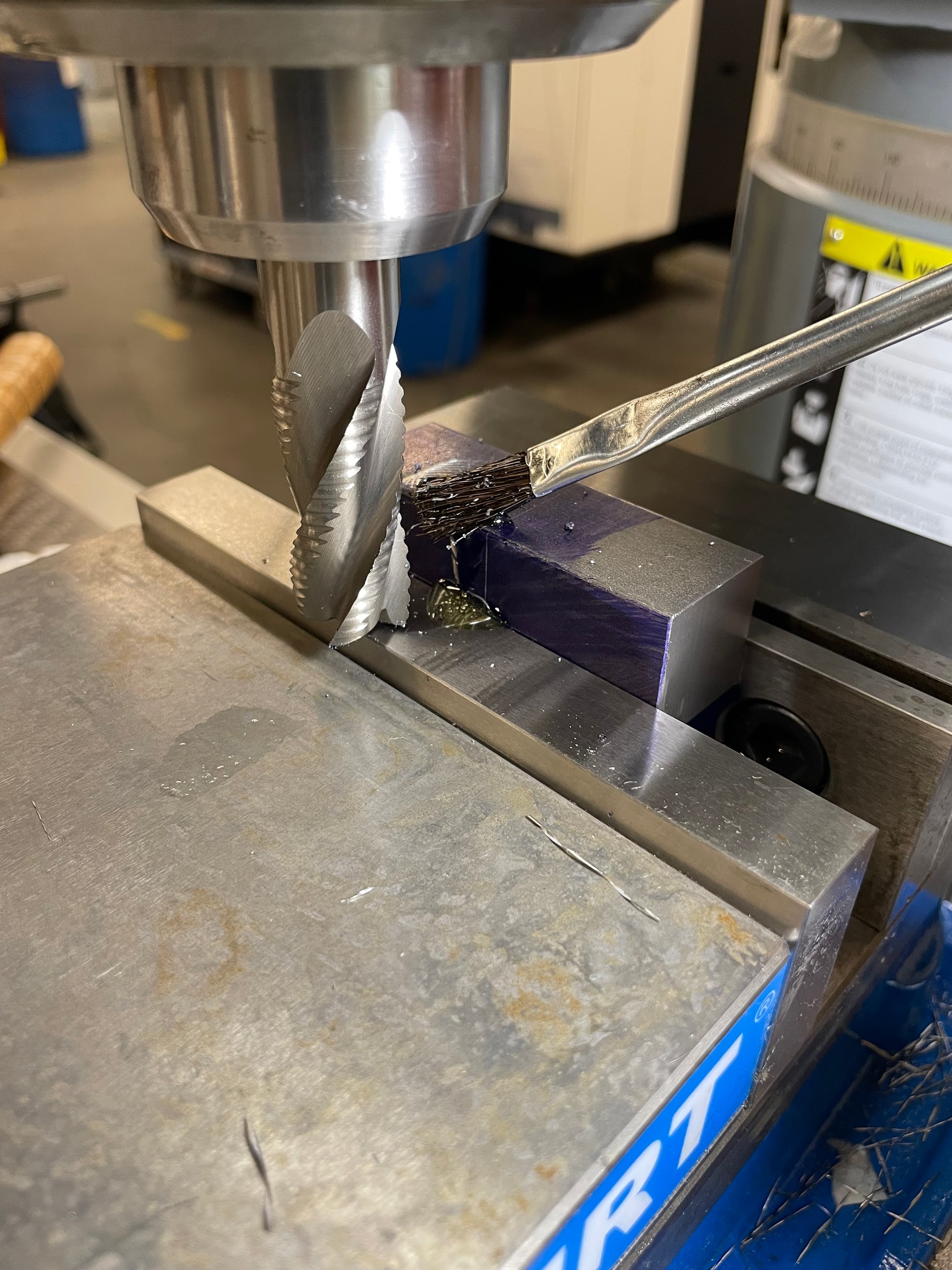
Step 13: Lube the tool and the work.

Step 14: Make the initial cut through the length of the slot at the calculated feed rate.

Step 14: Make the initial cut through the length of the slot at the calculated feed rate.
Step 14: Make the initial cut through the length of the slot at the calculated feed rate.
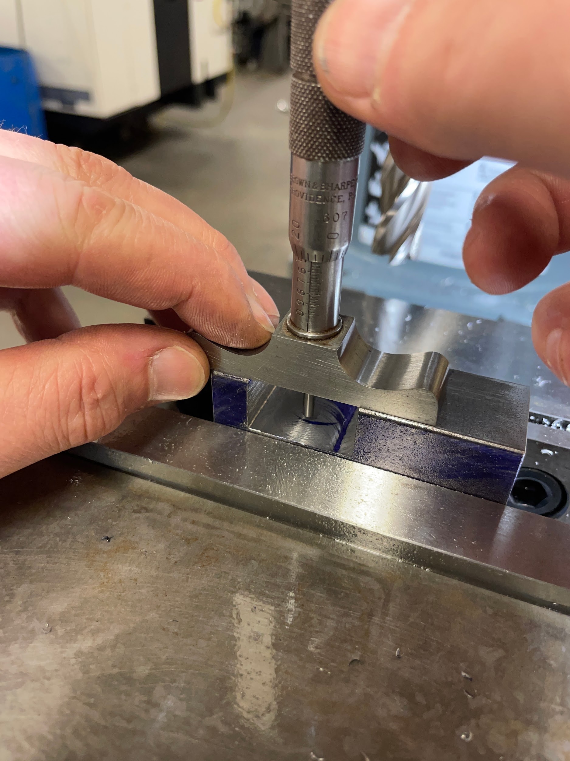
Step 15: Take a measurement to determine the amount needed to be removed in one direction.
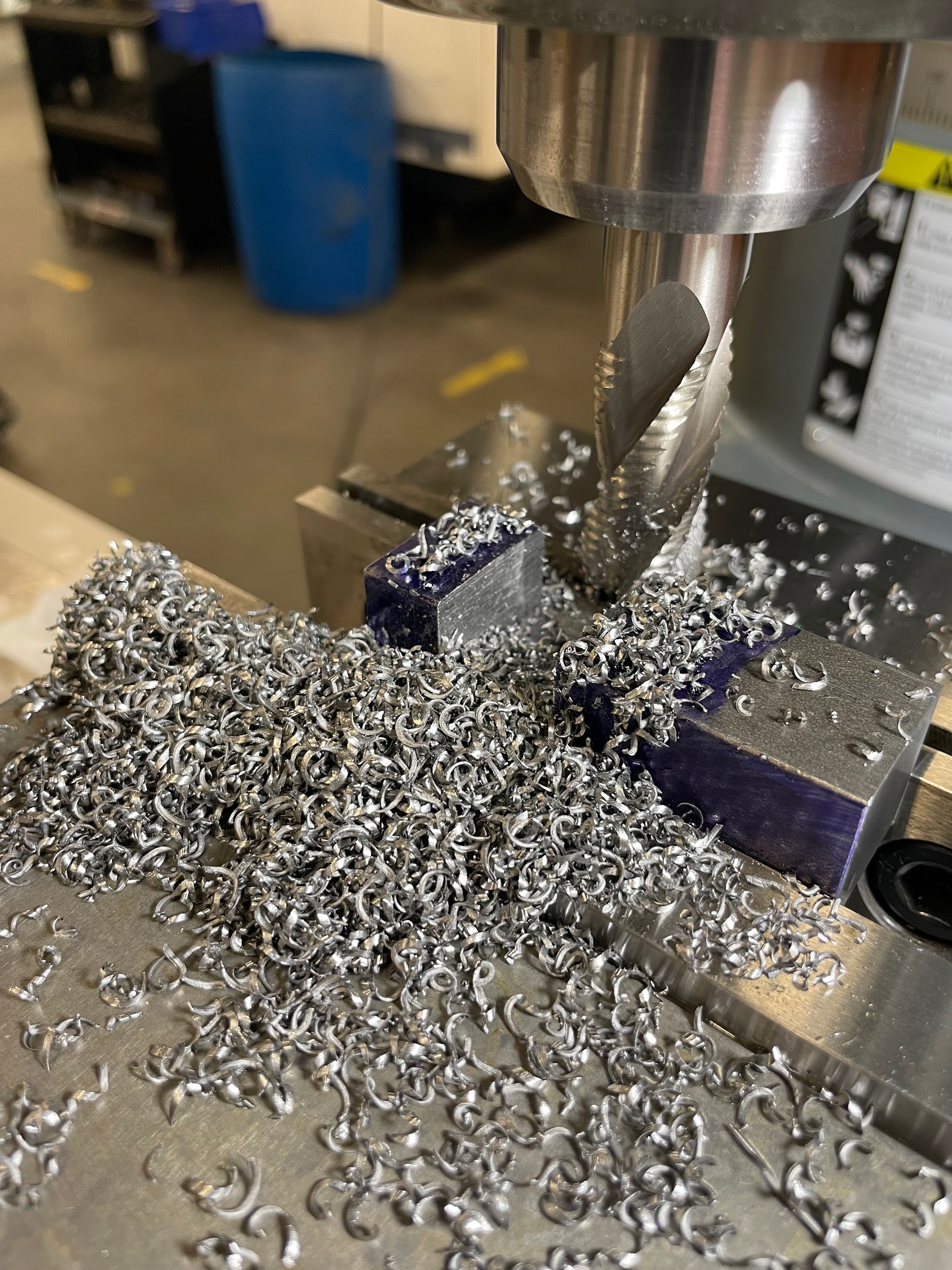
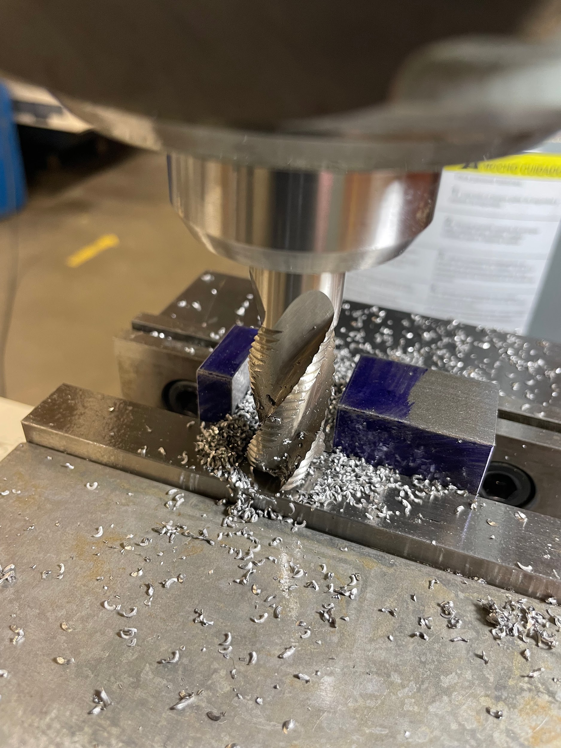
Step 16: Conventional cut the remaining material, leaving material on walls for finishing.

Step 16: Conventional cut the remaining material, leaving material on walls for finishing.
Step 16: Conventional cut the remaining material, leaving material on walls for finishing.
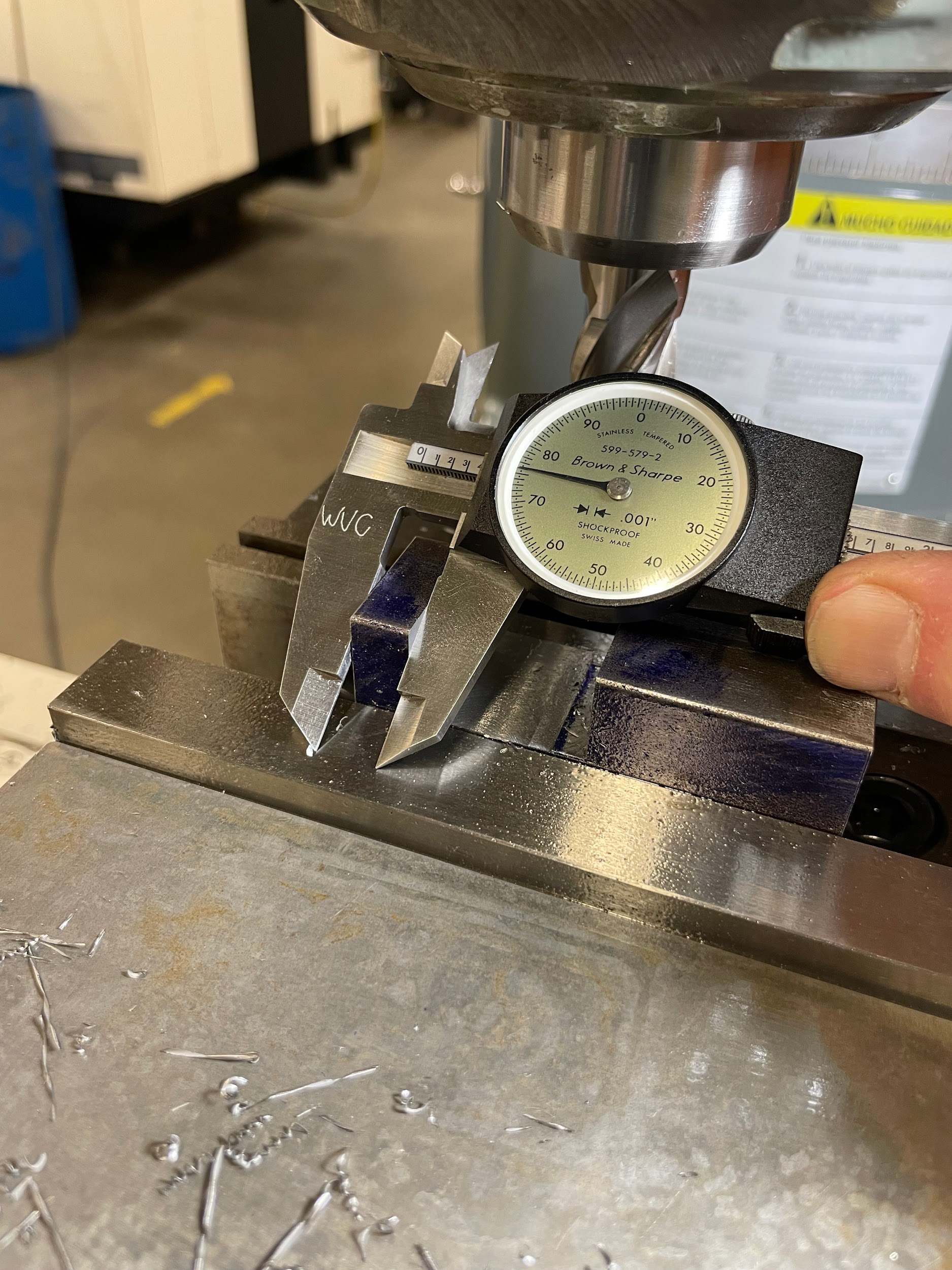
Step 18: Make a test cut just skimming the bottom and the side of the slot.

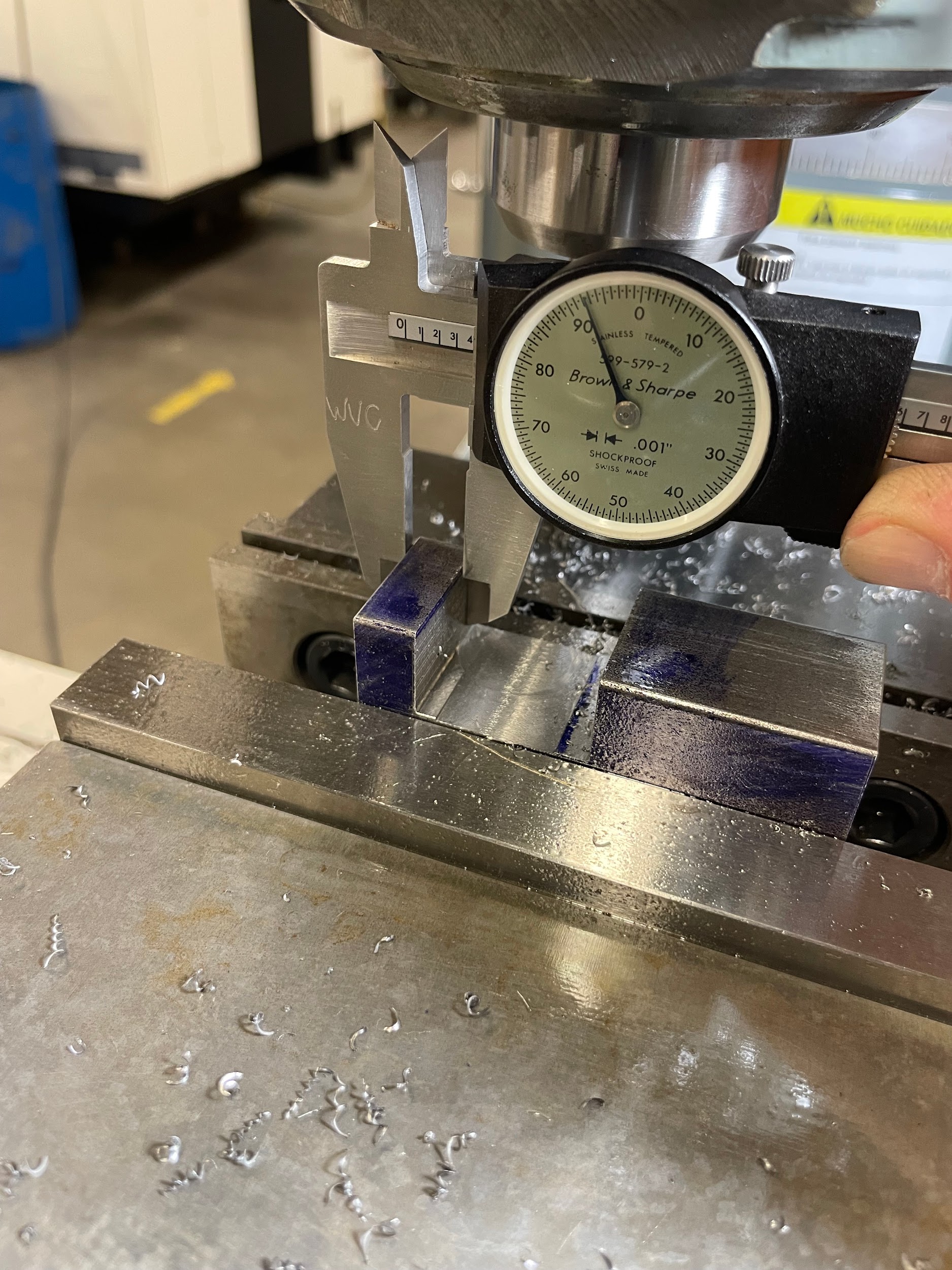
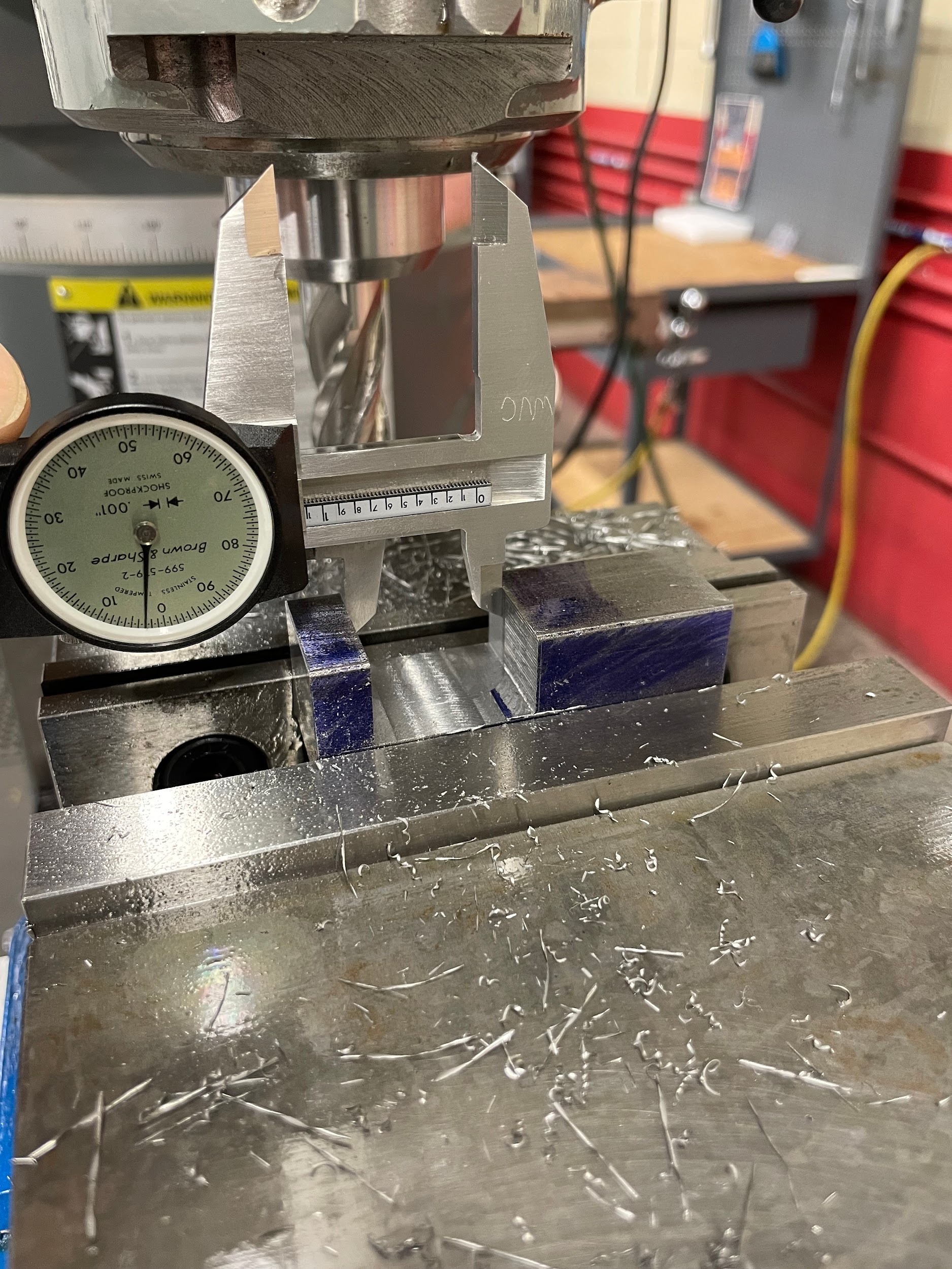
Step 20: Accurately measure the part.
Step 20: Accurately measure the part.
Step 22: Adjust the machine and make successive cuts in order to finish one side.

Step 22: Adjust the machine and make successive cuts in order to finish one side.
Step 23: Make a skim cut on the other side of the slot.

Step 25: Measure the slot and calculate the material needed to be removed to finish the slot.
Step 26: Adjust the machine and make successive cuts in order to finish the slot.

Step 26: Adjust the machine and make successive cuts in order to finish the slot.

Step 26: Adjust the machine and make successive cuts in order to finish the slot.
Step 26: Adjust the machine and make successive cuts in order to finish the slot.
Attributions
- Figure 9.164: Finished slot by Micky R. Jennings, courtesy of Wenatchee Valley College, for WA Open ProfTech, © SBCTC, CC BY 4.0
- Figure 9.165: Load a roughing end mill by Micky R. Jennings, courtesy of Wenatchee Valley College, for WA Open ProfTech, © SBCTC, CC BY 4.0
- Figure 9.166: Positioning the roughing cut by Micky R. Jennings, courtesy of Wenatchee Valley College, for WA Open ProfTech, © SBCTC, CC BY 4.0
- Video 9.43: Micky R. Jennings, courtesy of Wenatchee Valley College, for WA Open ProfTech, © SBCTC, CC BY 4.0
- Figure 9.167: Setting the depth of cut by Micky R. Jennings, courtesy of Wenatchee Valley College, for WA Open ProfTech, © SBCTC, CC BY 4.0
- Figure 9.168: Lube the tool and the work by Micky R. Jennings, courtesy of Wenatchee Valley College, for WA Open ProfTech, © SBCTC, CC BY 4.0
- Video 9.44: Micky R. Jennings, courtesy of Wenatchee Valley College, for WA Open ProfTech, © SBCTC, CC BY 4.0
- Video 9.45: Micky R. Jennings, courtesy of Wenatchee Valley College, for WA Open ProfTech, © SBCTC, CC BY 4.0
- Figure 9.169: Rough cut the slot by Micky R. Jennings, courtesy of Wenatchee Valley College, for WA Open ProfTech, © SBCTC, CC BY 4.0
- Figure 9.170: Finished roughing cut by Micky R. Jennings, courtesy of Wenatchee Valley College, for WA Open ProfTech, © SBCTC, CC BY 4.0
- Figure 9.171: Measuring left side of slot by Micky R. Jennings, courtesy of Wenatchee Valley College, for WA Open ProfTech, © SBCTC, CC BY 4.0
- Video 9.46: Micky R. Jennings, courtesy of Wenatchee Valley College, for WA Open ProfTech, © SBCTC, CC BY 4.0
- Figure 9.172: Roughing left side of slot by Micky R. Jennings, courtesy of Wenatchee Valley College, for WA Open ProfTech, © SBCTC, CC BY 4.0
- Figure 9.173: Roughing right side of slot by Micky R. Jennings, courtesy of Wenatchee Valley College, for WA Open ProfTech, © SBCTC, CC BY 4.0
- Video 9.47: Micky R. Jennings, courtesy of Wenatchee Valley College, for WA Open ProfTech, © SBCTC, CC BY 4.0
- Figure 9.174: Measuring the bottom of the slot by Micky R. Jennings, courtesy of Wenatchee Valley College, for WA Open ProfTech, © SBCTC, CC BY 4.0
- Figure 9.175: Measuring left side of slot by Micky R. Jennings, courtesy of Wenatchee Valley College, for WA Open ProfTech, © SBCTC, CC BY 4.0
- Video 9.48: Micky R. Jennings, courtesy of Wenatchee Valley College, for WA Open ProfTech, © SBCTC, CC BY 4.0
- Figure 9.176: Measuring finished left side of slot by Micky R. Jennings, courtesy of Wenatchee Valley College, for WA Open ProfTech, © SBCTC, CC BY 4.0
- Video 9.49: Micky R. Jennings, courtesy of Wenatchee Valley College, for WA Open ProfTech, © SBCTC, CC BY 4.0
- Figure 9.177: Measuring width of slot by Micky R. Jennings, courtesy of Wenatchee Valley College, for WA Open ProfTech, © SBCTC, CC BY 4.0
- Video 9.50: Micky R. Jennings, courtesy of Wenatchee Valley College, for WA Open ProfTech, © SBCTC, CC BY 4.0
- Video 9.51: Micky R. Jennings, courtesy of Wenatchee Valley College, for WA Open ProfTech, © SBCTC, CC BY 4.0
- Figure 9.178: Measuring width of slot 2 by Micky R. Jennings, courtesy of Wenatchee Valley College, for WA Open ProfTech, © SBCTC, CC BY 4.0
- Figure 9.179: Finished slot by Micky R. Jennings, courtesy of Wenatchee Valley College, for WA Open ProfTech, © SBCTC, CC BY 4.0
The process of using an end mill to cut long narrow features.
